基于摆线旋分原理的飞刀加工及其刀具的结构设计
2014-08-22波山西机电职业技术学院山西长治046011
吉 丽,闫 波山西机电职业技术学院,山西长治 046011
The slider groove and reverse taper are important parts in the gear sleeve of automobile synchronizers.Their processing quality can directly affect the overall safety of the gear sleeve and even the synchronizer.Due to the fact that the slider groove and the reverse taper are the inside surface and close to each other(as shown in Figure 1),the processing is rather difficult.
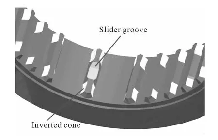
Figure 1.Diagram of slider groove and inverted cone
1.The current condition of processing of slider groove in the gear sleeve of synchronizer
Generally speaking,the slider grooves in the domestic automobile synchronizers mainly adopts the intermittent indexing cutting with formed cutter.With the increasing amounts of new products,the sizes and specifications of the auto-synchronizers are varying constantly and the number of customized formed cutters of companies is increased,so the result is that the great burden of the customized production exists for the maintenance and the use of different cutters.In addition,because of the big cutting force and the fact that most formed cutters are made of high-speed steel and the cutting can not be at a high speed,which affects the production efficiency.The correction of the cutter sharpeners is also troublesome,which will directly influence the production cost.
The developed countries such as Germany,Japan and USA have more advanced processing equipments in the processing of slider groove of automobile synchronizers[1].PRANEMA in Germany manufactures the SYNCHROFORM machine tool to realize the continuous cutting process of slider grooves.It adopts the cycloid rotational indexing method.Because of the high-speed cutting by using the highpower machine tools,the cutting efficiency has been improved by several times and the form precision has reached up to μm level[2].
Currently in China,only two companies in Shanghai and Chongqing use the German equipments to process some machine parts and the costs are relatively high,which can not be popularized due to the technological limits and the imports of all cutters and procedures.The Nanjing No.2 Machine Tool Factory introduced some techniques of WERA companies in Germany and has applied the patent in China[3].
After years of research,Tianjin University cooperated with a synchronizer manufacturer and developed the cycloid rotational indexing NC machine tool with independent intellectual property rights[4].
The machine tool adopts the open system.Both its software and hardware have some extending capacities which can process the slider grooves and reverse tapers of most gear sleeves and wheel hubs.
This paper mainly discussed the cycloid machining principle,established the flying cutting mathmatical model and designed the cutter as required by the practical application.
2.The cycloid rotational indexing principle
The rotational indexing processing is the synchronized rotation of working parts and the cutter.During the rotational process,the cutting and indexing are realized at the same time.Compared with the traditional indexing inconstant cutting,the rotational indexing cutting is continuous,which will greatly improve the cutting efficiency.The speed ratio of the working parts and the cutter can be changed in order to process the surface with different shapes.
The cycloid rotational indexing means the running route of the cutter’s edge follows the cycloid route which is very close to the real shape of the working parts.
When a moving circle is rolling along an unmoving circle,the running route of any point in the moving circle is an inside-circle cycloid.In this way,an ordinary outside cycloid and inside cycloid can be formed,as well as short and long ones.As shown in Figure 2,suppose the radius of the unmoving circle is R,the radius of the moving circle is r.When the moving circle starts rolling from Position I,Point N is the rolling point.When the moving circle is rolling to Position II,Position I and Position II forms an angle,and the self-revolving angle of the circle isθ.If the distance between Point P and the circle center is e,the running route of Point P can be shown as:
Where,θ=(1-R/r)α,α≥0,According to the nature of the cycloid,when the three T-shape grooves
If the slider grooves with determined radius are to be processed,D is determined,so the different cycloid could be obtained by changing the value of e.As shown in Figure 3,the short inside cycloid can be used to reach the real surface of the working parts(an arc in the case).The parameters of the gear sleeve are as follows:m=2.5、z=36、α =30°、R=23 mm.After calculation,the cycloid route is similar to an arc,the maximum value of the edge warping(the theoretical approximation error)is 0.000 197 mm[5].Therefore,the precision is high enough to meet the requirements of the working parts.are processed,R=3r,so r=(D-e)/2.The abovementioned equation could be changed into:
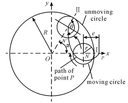
Figure 2.The formation of cycloid
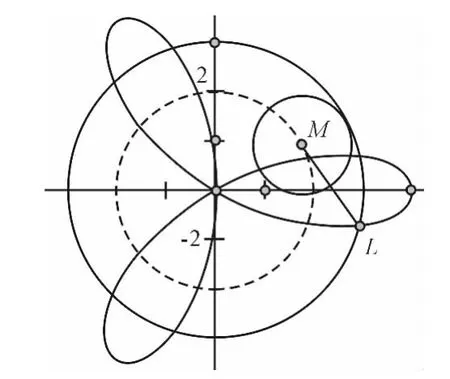
Figure 3.The processing scheme of inner cycloid
3.The establishment of the flying cutter mathematical model
After experiments,the cutting remains are large when using the formed cutter to cut the working parts through cycloid rotational indexing cutting.With the big cutting force,the high-speed cutters abrade very quickly and it results in the strong trebling when cutting.Therefore,this cutting process will adopt the method of running routes of flying cutters.
The so-called flying cutter processing is to install a self-made cutter in the cutter handle.Due to the fact that the chips fly around during cutting process,it is called“flying cutter”figuratively.In this processing case,the flying cutter is a self-made singleedge cutter.
As shown in Figure 4,the slider groove of the gear sleeve is in the shape of zigzag,so in this processing case,a flying cutter is used to run the route along the slider groove.
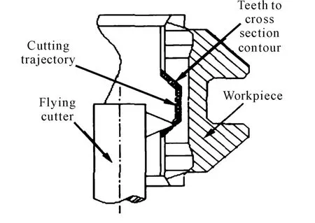
Figure 4.The slider groove shape and the knife tool path
There are three kinds of traditional cutting force mathematical models.The experimental formula is usually used in engineering to calculate the cutting force because it is simple with less number of variables.In this processing case,the flying cutter is like a lathe tool,cutting inconstantly.According to the experimental formula,the main cutting force could be calculated as follows:

In order to reflect the function of cutting the front angle,the front angle αis added in the original formula.So we can get:

After the experimental design,the determinants are the cutting depth,the feeding volume,the cutting speed and the front cutting angle.Table 1 shows the determinants and levels of the cutting experiment.
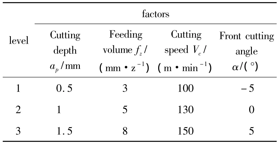
Table 1.The factors and levels in the orthogonal experiment
If the all-facor method is adopted,81 experiments have to be conducted.In order to reduce the experiments,the orthogonal experiment has been used to test the cutting force and Table 2 has been obtained along with the experiment results.
The multiple linear regression model was used to analyze the experimental results,and the Mathlab was used to solve the equation.The Mathlab model is as follows[6].

Formula 5 is the math model of the flying cutter cutting slider grooves in this processing case.
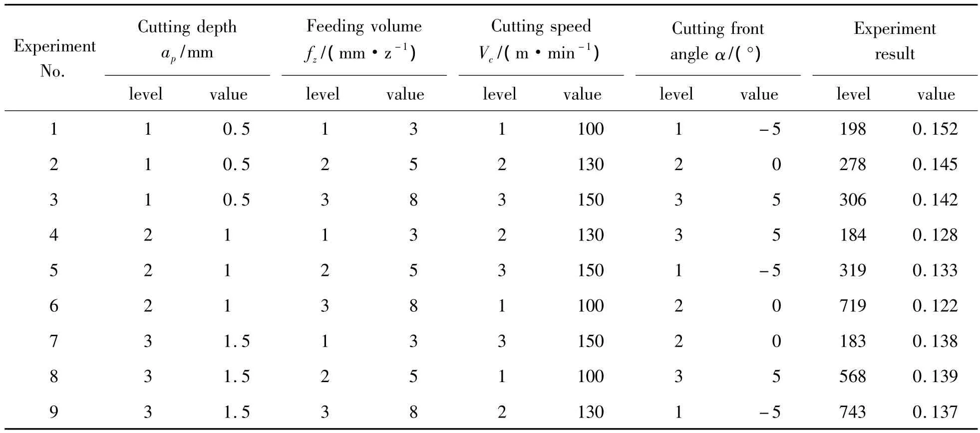
Table 2.The orthogonal experiment table and results
4.The structural design of the flying cutter
The complete design of the cutter is based on its function.This set of flying cutter has to take several things into consideration such as the material of the cutter,the cutting angle of the cutter,the combination of the cutter body and cutter edge,the connecting method of cutter system and the main axis and the shape of the cutter.
At present,20CrMnTi is used in most domestic gear sleeves.It has sound cutting capacity and can realize the high-speed cutting.
In this processing case,with reference to the sizes of the working parts and the cutter,the absolute cutting speed is.

According to the size and structure of the gear sleeve combined with the rotating speed of the main axis of the machine tool and the cutter axis,Formula(6)is used to determine that the cutting speed of this processing case is over 100 m/min,so it is better to choose the hard alloyed throw-away cutter chip.
In order to save the design time and reduce the cost of cutter,the indexable turning tool with reliable quality was chosen and the self-designed cutter handle has been fixed as well.
Take the above-mentioned factors into consideration,and the design of the cutter is as shown in Figure 5.
Due to the fact that the processing route is a trapezoid(the angle of 45°between the bottom line and the side line),the wedge angle of the cutter can not be over 90°.And the wedge angle can not be close to 90°so that the abrasion of the back surface of the cutter can be reduced.On the other side,if the wedge angle is too small,the strength of the cutter will not be enough so that the wedge angle should not be smaller than 50°.With all these considerations and combination with the size and specifications of the standard cutters,the wedge angle should be 55°or 60°,i.e.,the cutting chip should be in diamond shape or regular triangle.
The diameter of the cutter handle could be determined.Due to the great variety of the automobile synchronizers,the specifications of the gear sleeves vary a lot,so that the choice of cutter handle is rather rich.Apparently,the companies should reserve a series of handles to meet different needs.In this experiments,the diameter of the cutter handle isΦ30 mm,and the inside radius of the gear sleeve of synchronizer isΦ84mm.
The processing of slider groove is similar to boring cutter.In this processing case,we adopt the form of fixing the chip on the self-made cutter handle,as shown in Figure 5.
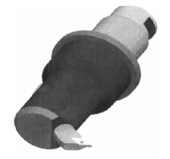
Figure 5.The knife structure
The position of the cutter handle in the machine tool and the connection method are discussed as follows.As shown in Figure 6,in order to position the cutter handle in the machine tool cutter axis,a groove is cut at the end of the cutter handle in order to position it through the hole in the cutter axis.The down side of the groove is a series of screw connecting with the cutter axis.
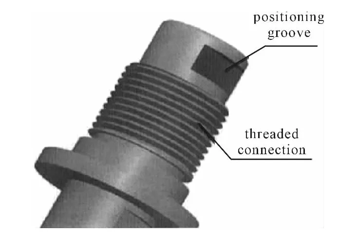
Figure 6.The knife rod end connection structure
5.The effects
At present,the processing method and the cutter have been adopted by the companies[7].Due to its high speed cutting,it has comparatively hight efficiency than that of the traditional cutting.After the tests,this processing method meets the precision requirement of the drawings.
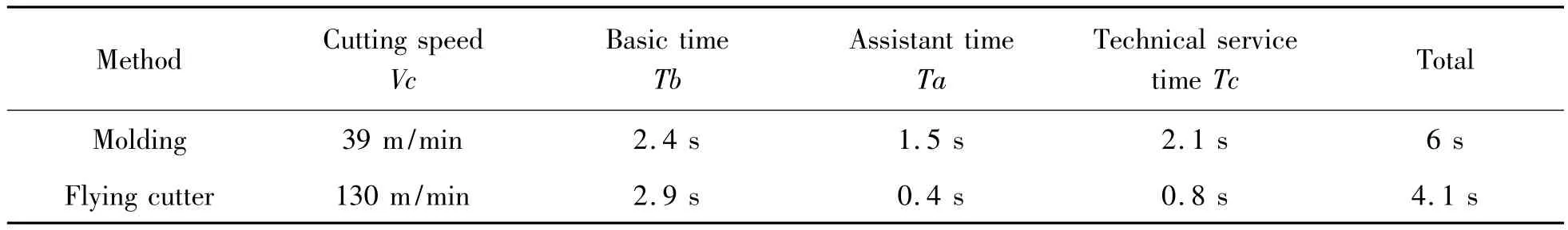
Table 3.Comparision of one-piece processing time between molding and flying cutter method
The rest time of the two processing methods(including the organization time,the physiological needs and rest time,the adjustment time and the piecework time)is the same,which is not accounted within the scope of the comparisons.Figure 7 is a table to measure the rough level of the surface of the slider groove by using the HOMMEL-WERKE rough level measuring instrument.Through the experiments,it has been found that the surface roughness Ra is 1.6 μm and it reaches the eighth level of precision,which meets the requirements of the drawings.The requirements of the factory were successfully completed under the premise of both the production efficiency(the surface roughness of the traditional molding process Ra is 1.4 μm and it is the same 8th level of precision).
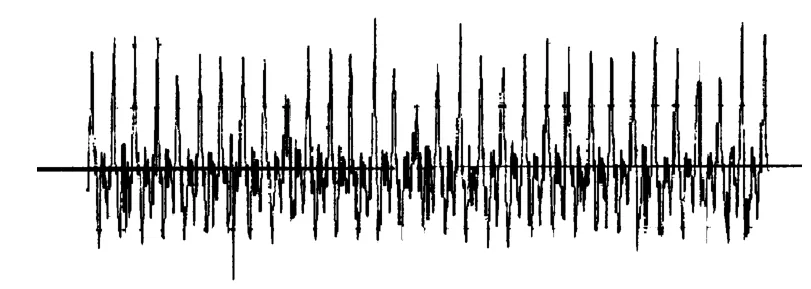
Figure 7.Fly cutting slider groove single peak surface roughness scan
With the running route method adopted,the independent programming can be realized according to the shape and size of the slider groove,extending the processing scope of the machine tool.It also uses the indexable cutter chip,solving the problem of edge abrasion in the traditional cutting method,reducing the cutter reservation and creating good economic benefit[8].
6.Conclusion
The purpose of this paper is to design the rotational indexing flying cutter system used in cutting slider grooves of the automobile synchronizers.The current condition of this method has been thoroughly discussed.By using the cycloid rotational indexing method,the processing mathematic model is established.Through analyzing the cutting material,the cutting condition and the structure of the machine tool,a flying cutter is designed.After testing and experiments,it has been proved that this cutter has high efficiency and good quality for the products.It has great popularization capacity in general.Our research group will further improve the precision and productivity by way of clamping,cutting the feed line,the cutting tool selection and dosage correct and reasonable process of content optimization,etc.in the future.
[1] Vera.German Machine Tool Co.Germany Vera spin machine[J].Metal working World,2006(6).
[2] Mage S.Germany Machine Co.Ltd Spin of Machine Tools[J].Automotive Manufacturing,2004(5):78.
[3] Zhaoxiaomin.A Synchronization is Inverted Bevel Gear Sets Extrusion Method and Tool[S].Chinese Patent,200410065486,2005-05-18.
[4] Lijia,Yuhuili,One New Machining Method for Gear Sleeve Slots of Automotive Synchronizers[S].Chinese Patent,200810056451,2008-05-08.
[5] Lijia,Yuhuili.A New Method for Auto Synchronizer Sleeve Slider Groove Machining[J].Automotive Technology,2003(9).
[6] Zhangyajun,Yanbo.The Mathematical Model of Flying Cutter Cutting of Automobile Transmission Synchronizer Gear Sleeve Slider Groove[J].Machine tool& hydraulics,2008(10).
[7] Yuxiaohong,Zhangzhenming.The Assisted Machining Time Calculation Process Based on The Model Law[J].Mechanical and Electronic.
[8] Yanbo,Lijia.The Slider Grooving Stability Studies of Knife Processing Auto SynchronizerSleeve[J].Machine Tool& Hydraulics,2011(19).
猜你喜欢
杂志排行

机床与液压的其它文章
- Introduction of the Fluid Control Engineering Institute of Kunming University of Science and Technology
- Yilin Hydraulic Group Harbin General Hydraulic Machinery Works Co.,Ltd.
- The Information for the Fifth International Symposium on Electro-hydraulic Power Transmission and Control Technology
- Analysis of magnetic field characteristics for different winding cylinder materials of a new type of magnetorheological damper*
- Emergency information integration for a kind of heterogeneous production system with uncertainty*
- Influence of salt fog test on the performance of the composite coating on avionics cases