重型数控龙门机床静压导轨承载能力研究
2014-08-22顿丹丹涛首都航天机械公司产品研究开发部北京100076
戴 钦,顿丹丹,金 涛首都航天机械公司产品研究开发部,北京 100076
1.Introduction
Hydrostatic slideway has many advantages such as high motion precision,low friction coefficient,long life span,high dynamic and static stiffness,and excellent vibration absorbing performance.Therefore,it is widely used in heavy-duty or super-heavyduty equipment such as hydrostatic rotary table of heavy-duty machines,equipment for earthquake test,and some key parts in large-scale and high precision machines.For the heavy-duty and super heavy-duty gantry machine with more than five-meter span,the weight of the movable gantry is up to several hundred tons.In order to ensure the stiffness and stability,hydrostatic slideway is usually used in the bottom guide of gantry.The picture of the machine is shown in Figure 1.
The oil pad is an important part of hydrostatic support,and its performance directly determines the carrying capacity and stability of machine gantry.Yang Jianxi and Meng Xinzhai[1]have established mathematical models for the static and dynamic performance of hydrostatic support,respectively.Sun Shouqun and Zhang Shaopeng[2]have calculated and analyzed the stiffness of oil film in hydrostatic guide by using the nonlinear finite element software MARC and the hydrodynamic simulation software FLUENT.Yu Xiaodong and Lu Huaimin[3]have calculated the pressure distribution of the oil film which is formed by circular and fan-shape oil pads by using a FORTRAN program and Visual Basic 6.0.Egyptian scholar Osman[4]and his team have analyzed the impact on the carrying capability and the stiffness of oil film,by testing the thickness of film,the pressure of oil chamber and the flow in experiments,and then compared it with the theoretical results.
Although many scholars have made numerous calculations and analyzed the oil film formed by different oil pads,there still exists blank research area for the hydrostatic slideway of heavy-duty machine.This paper studied the hydrostatic oil pad in heavyduty machine.The hydrodynamic model of the oil pad is established,the flow field of the film is simulated and the research of carrying capacity of heavy hydrostatic slideway is conducted.
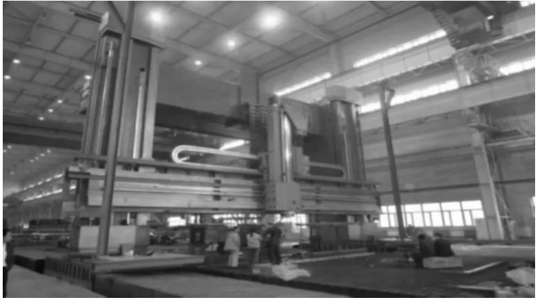
Figure 1.Heavy-duty CNC gantry machine
The paper is organized as follows.The hydrostatic slideway in a heavy-duty CNC gantry machine is introduced and the oil pad is described in Section 2,the hydrostatic oil film is modeled and the flow characteristic is analyzed in Section 3.The parameter of the hydrostatic oil film is tested in the heavy-duty CNC gantry machine,and the simulation results and experiment results are compared in Section 4.For engineering requirement,the simplified calculation method is proposed and the error is evaluated by using the simulation results and experiment results in Section 5.The conclusion is drawn in Section 6.
2.Description of hydrostatic slideway oil pads
Hydrostatic oil pad is adopted to support the weight of heavy-duty CNC gantry machine.The distribution of oil pads at the bottom of each slide is shown in Figure 2.There are sixteen oil pads at the bottom of each slide.Compared with the traditional rectangular oil pad,there is a rectangular bulge in the oil chamber.The hydraulic system adopts quantitative-type oil supply,and the hydraulic oil flows into the oil chamber through the inlet.When the pressure and the load of oil chamber reach a balance status,a stable film will be formed between the pad and the slide.At this status,it is the pure liquid friction state,and the friction coefficient is down to 0.000 5~0.001.
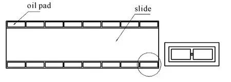
Figure 2.Oil pads distribution at the bottom of each slide
The hydrostatic oil pad along the direction of liquid flow is shown in Figure 3.h is the film thickness,d is the inlet diameter,q is the depth of the oil cavity,q1is the depth of the convex part of the oil cavity,x is any position which is along the direction of liquid flow,P1is the pressure of the oil cavity,P2is pressure of outside oil sealing edge,the pressure difference of oil sealing edge on both sides isΔP=P1-P2,the length of rectangular oil pad is L and the width is B,the length of rectangular oil cavity is l and the width is b.the quality of gantry is m.The oil film thickness is h.Some oil pads parameters for a model of heavy-duty gantry machine are shown in Table 1.Inlet flow is Q and dynamic viscosity is μ.Since the gantry is symmetrical,the oil pads of two slideways are the identical.
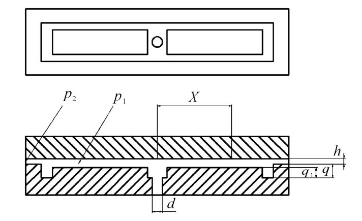
Figure 3.The hydrostatic oil pads along the direction of liquid flow
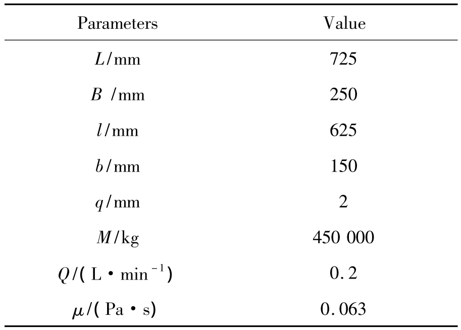
Table 1.Oil pads geometry and hydraulic oil parameters
3.Flow characteristics of hydrostatic oil film
Hydraulic oil is filled between the pads and the hydrostatic slideway,which forms hydrostatic oil film in working condition.If the fluid film[5-8]is incompressible,the Reynolds number Recould be calculated.Oil sealing edge formed by oil pads could be considered as fluid flow between parallel plates.Then the flow state of the internal of the oil chamber could be calculated.The shape of oil chamber is shown in Figure 3,and the value of parameters are shown in Table 1.Immersion area is F=b1,the distance from the pipe inlet to the flow at its full expansion is l'=.By calculating the flow in oil chamber,the two
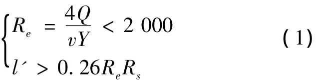
Therefore,without the consideration of load side for the film slip,liquid flow of oil sealing edge is in laminar flow region.In practice,the selected density of the hydraulic oil is900 kg/m3,and the viscosity of hydraulic oil is 0.063 Pa·s.The hydraulic system adopts quantitative-type oil supply and the flow at the entrance is 0.2 L/min.At the exit,as the hydraulic oil flows back into the tank directly,the pressure at the exit is considered the same as the environmental pressure,so the exit pressure is ambient pressure.
The geometry of film is symmetrical at the liquid flow direction and its vertical direction.During the simulation,a quarter of the oil film is modeled to reduce the number of the grid.In order to improve the accuracy of calculation,the oil film is marked into different areas.Firstly,mark the area with big changes at the borders.In order to reduce the computation cost,it is better to adopt the structure grid.The transitional area adopts the non-structure of tetrahedral structure grid;local refinement is applied on the edge of seal oil in order to improve accuracy.Then check the mesh quality,and output the grid file after it is qualified.The simulation model is shown in Figure 4.In this model;there are 255742 nodes,363484 elements and 10 element groups.
The boundary conditions of the computational domain is considered as follows:① speed inlet,Q=0.2 L/min;②pressure outlet,P2=0 Pa with the hydraulic oil coming back to tank;③set the geometric model of the symmetry plane as symmetry;④set the load surface as a fixed wall,and the space between fixed wall and fluid is under no-slip boundary condition;⑤the other side is under the default boundary condition.Film thickness is obtained as follows:h=0.03 mm,h=0.036 mm,h=0.038 mm,h=0.04 mm,h=0.042 mm,h=0.044 mm,h=0.05 mm.
SIMPLE algorithm is used to solve the established hydrostatic oil pads film model,and the curve conditions of the laminar flow could be met:for continuity and speed residual is less than,which indicate that the computing model and the quality of the segmentation are good,and the results are converged.
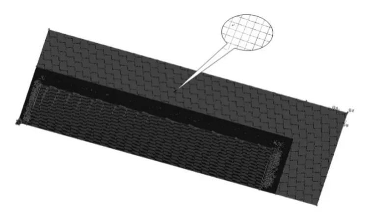
Figure 4.Quarter of the oil film simulation model
According to numerical simulation results,flow characteristics within the oil pad are obtained at different hydrostatic oil film thickness.When the film thickness is set to h=0.036 mm,pressure nephograms of oil pads internal flow field are shown in Figure 5,Figure 6,and their velocity nephograms are shown in Figure 7 and Figure 8,while the pressure field distribution from the exit position to the center of oil pads is shown in Figure 9.
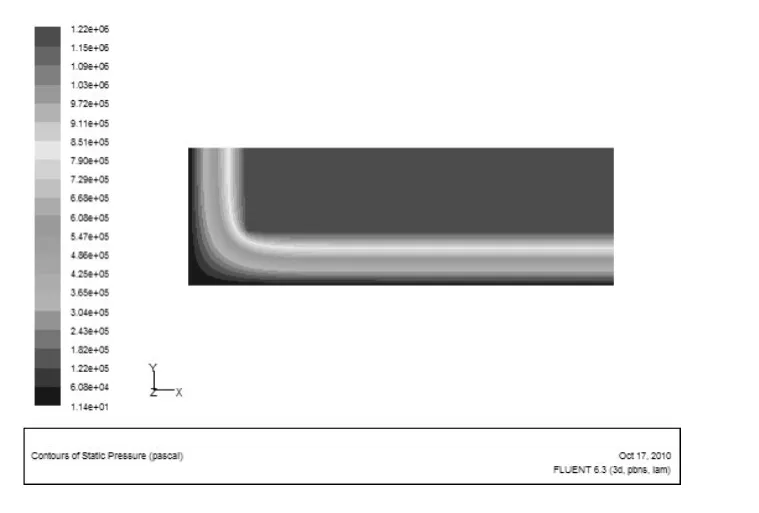
Figure 5.Pressure field of oil pad
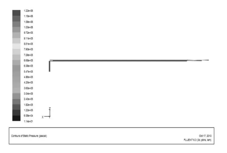
Figure 6.Pressure field of symmetry plane along the film length
According to the simulation results,the oil chamber pressure almost remained constant,the pressure of oil sealing edge is reduced gradually to environmental pressure.Maximum velocity is obtained at the entrance of the oil pad.With the flow of liquid into the oil chamber,the speed is decreased gradually.Due to the protruding part,some liquid flows reversely into the central cavity of the oil chamber,and the flow rate near the edge of the seal oil is increased,but the flow rate is stable in the internal of the oil sealing edge.
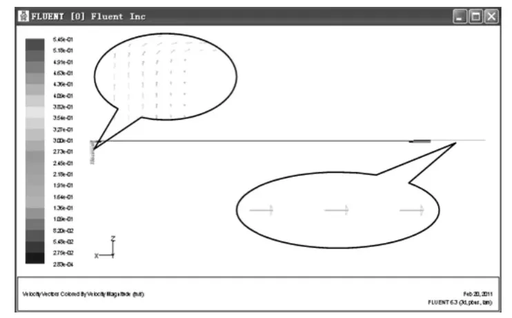
Figure 7.Velocity field of symmetry plane along the film length
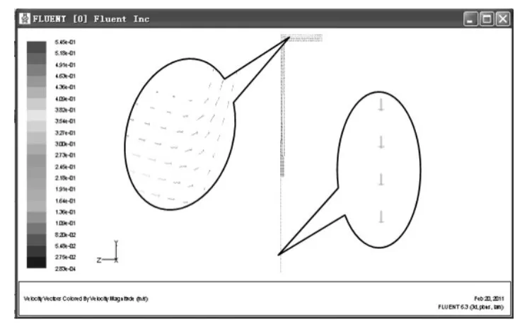
Figure 8.Velocity field of symmetry plane along the film width
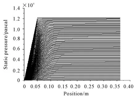
Figure 9.Simulation of pressure distribution
4.Experiment study
In order to validate the reliability of the simulation results,an experiment is designed to test the thickness of film when a gantry machine tool works under a stable working condition.The total weight of gantry is 4.5 ×10⁵kg.The weight of gantry is relatively uniform on the structure of oil pads,and the weight of every point is uniform,so the film thickness of each gantry position is consistent.The weight of overall gantry converted to each oil pad pressure is 1.38 ×10⁵N.
The experimental system consists of three components:eddy current sensor,data acquisition System and computer system.
The eddy current sensor is installed on the magnetic base.The magnetic base is placed on the upper structure of oil pad,and the eddy current sensor probe is directly connected to the working surface of slideway,as shown in Figure 10.The signal of the eddy current sensor is sampled by LMS system,and the acquired data is translated and entered into a computer.
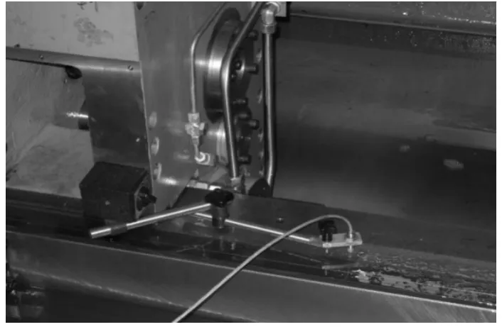
Figure 10.Current eddy sensor installation
Turn on the oil pump and the hydraulic oil is pumped into hydrostatic pads.After a few minutes,hydraulic oil flows out of the return pipe and then a stable oil film is formed between hydrostatic slideway and slide.The displacement change is obtained through analyzing eddy current sensor voltage variation by the data acquisition system as shown in Figure 11.
The oil film thickness is 0.036 mm according to the data acquisition system.The simulation data is matched and it is shown that the oil film thickness is 0.040 mm in the actual oil chamber pressure.Compare the oil film thickness according to the experimental results with the simulation results,the tolerance is 11.1%.
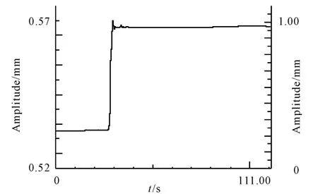
Figure 11.The film thickness response
5.Theoretical analysis method
In order to adapt to the engineering design of hydrostatic oil pad,theory calculation equation of oil pads carrying capacity is obtained through theoretical derivation.It is verified by experimental data and finite element analysis data,and then calculation precision is checked.The actual oil pad is shown in Figure 3,and the simplified form is shown in Figure 12.
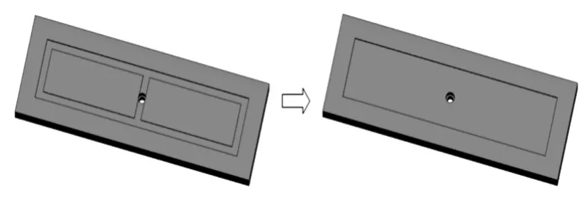
Figure 12.Simplified model of hydrostatic oil pads
From the flow equation[7]of the gap between two parallel fixed plates,the following equation could be obtained:
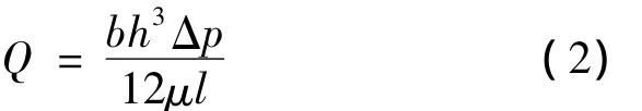
Equation(2)could be rewritten as follows:
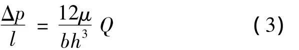
In the above equation,lpstands for pressure loss per unit length along the liquid flow direction;Finally,the pressure P of any position along the liquid flow direction could be obtained:

The pressure of oil sealing edge along the liquid flow direction is:

Rectangular plane oil pad of hydrostatic support is composed of four narrow parallel plates,and the hydraulic oil flows into the oil chamber from inlet of the center of rectangular oil chamber and flows out from the surrounding.Then calculate the flow along length and width direction of the oil pads,respectively.
By using Equation(2),the following equations could be obtained:
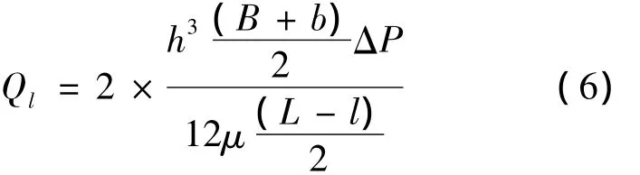
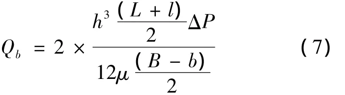
Therefore,the total flow could be obtained:
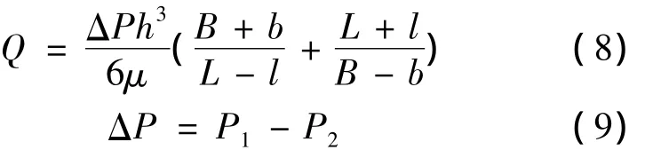
P2is the environmental pressure,and P2=0.
Therefore,combining the Equation(8)and(9),one could obtain the following equation:
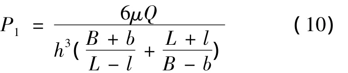
With Equation(10),the following equation could be obtained:
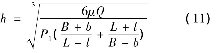
The effective load area of oil pads could be obtained by the pressure distribution as follows:

Oil chamber pressure is directly related to the carrying capacity of the oil pad on the same load area condition.In order to verify the reliability of numerical simulation and theoretical simplified model calculation results,pressure in oil chamber is compared for the different oil films thickness.As shown in Table 2,both of methods exists tolerance,but the maximum error is less than 10%.
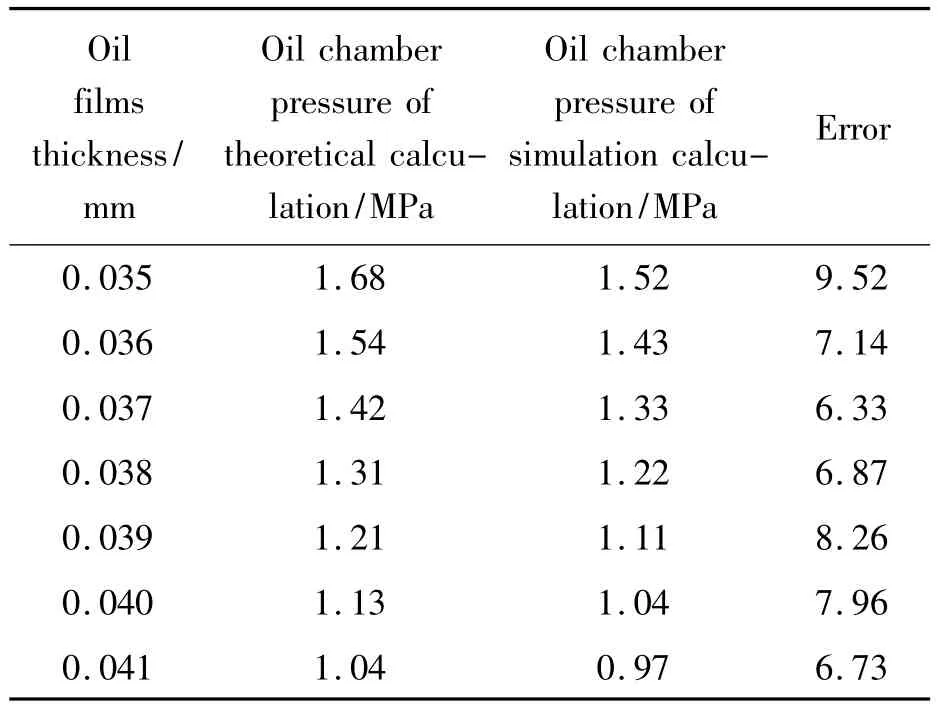
Table 2.Oil chamber pressure contradistinction under different oil films thickness
The oil film thickness is 0.036 mm according to the data acquisition system.The theoretical simpli-fied calculation data is matched and it is shown that the oil film thickness is 0.041 mm in the actual oil chamber pressure.Compare the oil film thickness through the data acquisition system with the theoretical simplified calculation result,and the tolerance is only 13.8%.
6.Conclusion
The oil film of hydrostatic slideway in a heavyduty gantry CNC machine is simulated with three-dimensional CFD model.Since the oil film of the hydrostatic pads fluctuate near the oil sealing edge,3D symmetric simulation model is adopted,which reduces the number of grids and improves calculation speed,so that the accuracy and the reliability of calculation could be increased.The carrying capacity of heavy hydrostatic slide guide,the pressure and the velocity characteristic of flow field are analyzed.The experimental data obtained from the heavy-duty gantry machine show that the simulation results are correct.For the requirement of engineering,the oil film carrying capacity is analyzed with simplified theoretical method.The precision of the simplified method is evaluated and the effectiveness is verified by the experimental data.The simplified calculation method is proposed to design the oil pad on heavy-duty gantry CNC machine hydrostatic slide guide.
[1] Yang Jianxi,Meng Xinzhai,Meng Zhaozhong.New E-quations for the Static Characteristic of Hydrostatic Bearing and Their Application[J].ENGINEERING SCIENCE,2002 .4(5).
[2] Lu Huayang,Sun Shouqun.FEA on the Oil Film of the Hydrostatic Slider[J].MACHINE TOOL & HYDRAULICS ,2007,35(10):46-49.
[3] Osman T A,Dorid M Z,Mokhtar M O A.Experimental Assessment of Hydrostatic Thrust Bearing Formance.Tribology International[J].1996,29(3):233-239.
[4] Lamikiz A,Lopez de Lacalle L N,CelayA.Machine Tool Performance and Precision[M].London:Springer London LTD,2009.
[5] Shao Junpeng,Zhang Yanqin,Li Pengcheng.Static Flow Simulation Of Hydrostatic Bearing Ellipse and Sector Curve Based on FLUENT[J].LUBRICATION ENGINEERING,2007,32(1):93-95.
[6] Jaw-Ren Lin.Surface Roughness Effect on the Dynamic Stiffness and Damping Characteristics of Compensated Hydrostatic Thrust Bearings[J].International Journal of Machine Tools and Manufacture,2000,40(11):1671-1689.
[7] Chen Yansheng.Hydrostatic bearing principle and design[M].Beijing:National Defense Industrial Press,1980.
[8] Ming Zhao,Zhengdong Huang,Liping Chen.Multidisciplinary design optimization of tool head for heavy duty CNCvertical turning mill[J].Engineering Computations,2008,25(7):657-676.
