Steady thermal hydraulic characteristics of nuclear steam generatorsbased on the drift flux code model∗
2014-08-05ZHANGXiaoYing张小英CHENHuanDong陈焕栋BAINing白宁ZHUYuanBing朱元兵RENZhiHao任志豪andHUANGKai黄凯
ZHANG Xiao-Ying(张小英),CHEN Huan-Dong(陈焕栋),BAI Ning(白宁),ZHU Yuan-Bing(朱元兵),REN Zhi-Hao(任志豪),and HUANG Kai(黄凯),
1School of Electric Power,South China University of Technology,Guangdong 510640,China
2China Nuclear Power Technology Research Institute,Shenzhen 518026,China
Steady thermal hydraulic characteristics of nuclear steam generators
based on the drift flux code model∗
ZHANG Xiao-Ying(张小英),1CHEN Huan-Dong(陈焕栋),1BAI Ning(白宁),2ZHU Yuan-Bing(朱元兵),2REN Zhi-Hao(任志豪),2and HUANG Kai(黄凯)2,†
1School of Electric Power,South China University of Technology,Guangdong 510640,China
2China Nuclear Power Technology Research Institute,Shenzhen 518026,China
To investigate the steady thermal hydraulic characteristics of U-tube steam generator(SG),a 1D simulation code based on the four-equation drift flux model is developed.The U-tube channels presumably consist mainly of the primary channel,secondary channel,and tube wall.In the sub-cooling regions of the primary and secondary channels,flow is simulated using the single-phase flow model,whereas that in the boiling regions of the secondary channels is simulated using the four-equation drift flux model.The first-order equations of upwind difference are derived based on the staggered grid.Steady-state thermal hydraulic parameters are obtained with a cross-iteration scheme of heat balance and natural circulation requirement.The developed code is applied to analyze the SG behavior of the Qinshan I Nuclear Power Plant under 100%,75%,50%,30%,and 15%power conditions.Analysis results are then compared with the simulation results obtained using RELAP5.
U-tube steam generator,Thermal hydraulic characteristic,Steady simulation,Four-equation drift flux model
I.INTRODUCTION
The U-tube steam generator(SG)is a heat exchanger that connects the primary and secondary coolant loops in a nuclear power plant(NPP).According to worldwide statistics, operational accidents of SG-related pressurized water reactor(PWR)account for a large proportion of all PWR accidents[1].Approximately 1/4 of the unplanned outage cases in PWR NPPs are caused by SG failure.Given that the flow and heat transfer in the primary and secondary loops are closely connected to the safety and stable operation of the SG,it is of importance to understand their thermal hydraulic characteristics.
The U-tube SG can presumably be a nonlinear,complex system with many flowing parameters.Studies on the thermal hydraulic behavior of SGs have achieved greatly.The followings are examples of SG simulation codes.The THEDA2 code developed in the U.S.uses 3D conservation equations of mass,momentum,and energy for a homogeneous equilibrium mixture(HEM)model[2].The ATHOS code applies either the three-equation HEM model or the four-equation drift flux model with options for 1D,2D,and 3D analyses[3].The THIRST code developed by AECL for 700MWe SG,is a 1D thermal hydraulic[4].Several thermal hydraulic codes for NPP SGs were developed in China.Based on the 1D separated fluid model,the SGTH-2 performs steady analysis of the U-tube SG[5].The MOFS is based on the 1D HEM model[6],while the SG code for high-temperature gas cooling reactors follows the 2D HEM model[7].
Most of the existing thermal hydraulic codes for NPP SGs utilize the classical HEM model,which treats the two-phaseflow of steam and water as a uniform mixture.However,it usually simulates the flow in the secondary loop with areaaveraged variables.Given that coolant temperature varies significantly from the top to bottom of the U-tube bundles, both temperature and heat transfer coefficients vary considerably in the two flows.To examine the thermal-hydraulic characteristics of NPP SGs thoroughly,a code with a detailed model shall be developed.
In this paper,we present a thermal hydraulic code for NPP SGs in a geometric model composed of the primary and secondary loops,U-tube,and steam room.The unique secondary loop model is divided into hot and cold sides,and the flow in it is simulated using the four-equation drift flux model and is analyzed thermal-hydraulically through coupling with heat transfer of the tube wall.Finally,the code is used to implement and verify the Qinshan NPP SG.The thermal hydraulic parameters are computed at 100%,75%,50%,30%,and 15% power rates.
II.GEOMETRIC MODEL
Given the complicated actual structure,the geometry of the nuclear SG should be simplified in modeling and thermal hydraulic simulation.This work considers the U-tube NPP SG. The primary loop of the SG is assumed as a straight tube of equal length.The secondary loop is circular and consists of the water supply chamber and the descending and ascending channels.The ascending channel consists of the sub-cooling, boiling,and ascent sections.In the secondary loop,the division of hot and cold sides is defined by the flow direction in the primary loop.The side with the primary inlet flow(the hot side)is hotter than the side with the primary outlet flow (the cold side).The SG structure is composed of the primary and secondary loops,heat transfer tube,and steam room,as shown in Fig.1.The straight section of the two loops is 7-mlong.The U-tubes are 0.022m in diameter,with a total length of 16m.

Fig.1.Simplified geometric frame of the SG.
III.FIELD EQUATIONS
In the U-tube SG,the flow types are of the single-and two-phase regions.Specifically,the flow in the primary loop and in sub-cooling sections of the secondary loop remains single-phase,whereas the two-phase region is illustrated by the flow in the boiling sections of the secondary loop.The two-phase regions are complicated in terms of flow and heat transfer.Thus,two sets of governing equations are established to model the single-and two-phase flows.
A.Balance equations for single-phase regions
In the sub-cooling sections of the U-tube SG,the singlephase region covers the primary loop,descending channel, and sub-cooling sections of the secondary loop.These regions utilize the single-phase flow model,and the respective balance equations of mass,energy,and momentum are as follows:

B.Balance equations for two-phase regions
The two-phase flow is mainly observed in the boiling section of the secondary loop of the U-tube SG.The equation of the four-equation drift flux model governs this region.This equation considers the velocity slipurat the two-phase interface and the variation in void fraction along the flow path.In our work,the 1D,area-averaged governing equations of the four-equation drift flux model used are expressed as[8]:

where the subscript“m”pertains to fluid mixture parameters;ρmis density;Gmis mass rate;umis velocity;hmis enthalpy; andur=ug−ufis the relative velocity of the liquid and gaseous phases.
C.Heat transfer model
We model the heat transfer between the primary and secondary loops in the U-tube SG through the heat conduction of the tube wall.The heat transfer of the U-tube wall can then be simulated through 1D conduction in the cylindrical geometry.The convection heat transfer rate between the wall and the coolant is the source term,and the heat conduction equation is given by

D.Correlations
To close the field equations discussed above,we must determine the correlations in the thermal property of the fluid and wall materials,as well as the criteria for the different flow structures,resistances,heat,and mass transfers.Theunknown variables that must be derived from correlations includeρm,cp,m,Γg,hf,hg,τwf,τwg,Uwf,Uwg,Uhf,Uhg,q,ρf, andρg.
To identify the thermal property of water and steam,we apply the formulas provided by the industrial standard IAPWSIF97[9].The property of the Incoloy-800 alloy is considered for the tube wall.Moreover,we apply the model of Taitel and Dukler in the structural criteria for flow[10].According to their model,bubble flow transitions to slug flow when bubble speedubis greater than Taylor bubble speedutbgiven a low flow rate in the tube with a small diameter tube(Gm<2000kg/(m2s)).This transition occurs when the void fraction is greater than 0.5 at an increased flow rate (Gm>3000kg/(m2s)),as shown by

The transition from slug flow to annular flow can be determined through the superficial velocity and the Kutateladze (Ku)number of the flow[11].The transition is observed in the flow in the channels with small diameters when gaseous superficial velocity exceeds the critical superficial velocityjg,crit.However,the transition is initiated when the gaseous Ku number is greater than the critical Ku number,as expressed by

The flow resistance in the U-tube SG considers the resistance to both gravitation and friction.The Darcy formula is applied in relation to the friction resistance of the singlephase flow.The split-phase friction model of Martinelli is employed[11]in relation to the friction resistance in the twophase flow as:

The convective heat transfer coefficient of the single-phase flow is calculated using the D–B formula with regard to flow in the primary loop and in the pre-heating section of the secondary loop.The D–B formula is calculated according to Chen’s equation for the boiling section of the secondary loop [12],
The onset of nucleate boiling is computed using the model developed by Bergles and Rohsenow[13]:

IV.NUMERICAL SCHEMES
A.Numerical schemes of the flow field
In our solution,we apply the semi-implicit difference scheme.We treat the convection terms in the mass and energy equations,the pressure gradient,and the two-phase mass transfer in the momentum equation implicitly,whereas all other differential terms are examined explicitly.The staggered grids are applied in discretization,and two groups of control volumes are established in the same flow channel. The control volumes for pressure,void,density,and enthalpy are arranged in a staggered formation along with those for velocity.The mass and energy equations are discretized given thecontrolvolumegroupsi−1,i,andi+1,whicharealsoimplemented by control volume groupsj−1,j,andj+1 given the momentum equation.The values of the flow parameter are presumably uniform in all control volumes.Fig.2 depicts the established staggered grids and control volumes.

Fig.2.Staggered grids for the discretization of flow conservation equations.
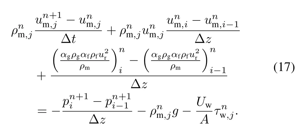
In relation to the four-equation drift flux model used in the secondary loop,the semi-implicit discretization equations are listed below[13]:

The discretization equations of the single-phase flow in the primary loop are similar in form to those given above. To solve these discretization equations,we adopt a velocity–pressure correction scheme.First,the unknown pressure of the new time step is assigned a value equal to that of the old time step.Subsequently,the momentum equation is solved to estimate the velocity value of the new time step.Once the mixture mass,gaseous mass,and mixture energy equationsarerearranged,weobtainthefollowingmatrixequations for

We apply a large time step,such as Δt=106s,for the steady state analysis.In this case,the time-derivative term is very small and can be disregarded in the discretization equations.Thus,the balance equations above can then be applied to the steady-state solution.
B.Solution for the U-tube wall conduction
Equation(8)is integrated into cylindrical volume 2πrdrdlat the time step Δtin relation to the heat conduction of the U-tube wall to generate the discretization equation for wall temperature.
C.Cross-iteration of heat balance and the natural circulation condition

In the U-tube SG,heat transfer is simultaneous in the primaryandsecondaryloops;thus,flowandheattransferinboth loops must be coupled for solving.We adopt a coupled iteration scheme that converges these factors when both heat balance and the natural circulation condition are satisfied.In heat balance,the heat transfer in the primary loop is equal to that in the secondary loop.In the natural circulation condition,the head of driving pressure must meet the total pressure drop of the entire system,that is,
In the iteration of heat balance,the heat fluxes in the primary and secondary loops are initially assumed to be a group of values.Subsequently,matrix Eq.(18)is solved to determine the flow parameters.The heat fluxes in the two loops are then computed in turn.In addition,the heat balance condition is validated.If the difference in heat flux between the primary and secondary loops is greater than a preset limit, the temperature of the coolant that enters the primary loop is corrected and a new iteration of heat balance is initiated.
In the iteration of natural circulation,the dichotomy scheme is applied.First,the value of flow rateWis set,and the difference in pressure head and resistance is computed asf(W)=DH−D.The flow rate is then modified slightly to flip the sign off(W′).The value of the flow rate is updated byWn+1=(W+W′)/2.The corrective iteration ofWcontinues untilf(W)meets a pre-set limit.Based on the theoretical model above,we therefore develop a code for the steady-state thermal hydraulic simulation of the nuclear U-tube SG.A numerical scheme is also established using MATLAB software.
V.SIMULATION RESULTS
The steady-state thermal hydraulic characteristics of the SG in the Qinshan 300MW PWR are investigated with respect to the thermal hydraulic code presented for nuclear U-tube SGs.The grid gap measures 1.2m along the U-tube length.Moreover,this study considers five cases under different power conditions,namely,100%,75%,50%, 30%,and 15%.The results at the 100%power condition are compared with those simulated using the RELAP5 code[14]. Table 1 lists the required computation parameters given this power condition.
Figures 3–7 show the computed steady-state thermal hydraulic parameters at the100%power level.The tube lengths are 0–8m and 8–16m for the hot and cold sides of the secondary loop,respectively.The results of the primary loop are plotted according to full tube length,whereas those of the secondary loop are plotted based on half tube length.Fig.3 presents the temperatures of the coolant in the primary and secondary loops and of the tube wall.The coolant temperature decreases along the tube in the primary loop;in the secondary loop,however,the inlet coolant is slightly sub-cooled.Thus,the coolant temperature increases to saturation level after a short distance.

TABLE 1.Condition parameters for 100%power.

Fig.3.Temperatures of the primary fluid(■,□),secondary fluid(•,◦),andU-tubewall(▲,△)intheSG.Thesolidsymbolsrepresentsthe results of the current work,and the blank symbols denote the results obtained from RELAP5.
The simulation results with our code differ only slightly from those obtained with RELAP5.With respect to the coolant temperature of the secondary loop,our results are slightly lower than those derived from RELAP5.This may be attributed to different correlations assigned to the convection coefficient.In RELAP5,a modified correlation of the convection heat transfer coefficient(Nu=2.0+ 0.74Re1/2Pr1/3)is applied to the single-phase liquid and sub-cooled boiling regions[14],whereas our study utilizes the D–B correlation.So,our technique generates a convection coefficient value that is smaller than that obtained with RELAP5.Temperature of the U-tube wall varies along the lengths in a manner that is almost similar to the coolant in the primary loop.This is ascribed to the fact that the heat resistance of the primary loop is much smaller than that of the secondary loop because the latter displays a noticeable fouling resistance.

Fig.4.Phase velocity in the hot((■,□)and cold((▲,△)channels of the secondary loop under the 100%power condition.The solid symbols represent the results of this work,and the blank symbols denote the results obtained from RELAP5.

Fig.5.Enthalpy of the fluid in the primary and secondary loops.
Figure 4 displays the gaseous and liquid velocities of the flow in the secondary loop under the 100%power rate.Both velocities increase continually in the secondary loop from the lower room to the steam room with tube heating and coolant boiling.The two-phase velocities increase in the steam room as a result of the expanding area.Furthermore,gas velocity is always higher than that of liquid because gas phase flow is affected by buoyancy.Nonetheless,the RELAP5 results are 5%higher than those of our code.
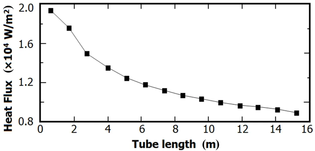
Fig.6.Heat flux on the interior of the U-tube wall.
Figure 5 exhibits the variation in coolant enthalpy along the tube lengths in the primary and secondary loops.Fig.6 shows the heat flux on the interior of the U-tube wall,which is equal to that of the exterior of the U-tube in steady-state analysis.The coolant enthalpy in the primary loop continues to decrease along the tube length with heat transfer from the primary to the secondary loops,whereas that in the secondary loop continually increases throughout the process as depicted in Fig.5.The heat flux on the interior of the U-tube decreases with tube length as the temperature difference between the tube wall and the coolant decreases along the tube(Fig.6).
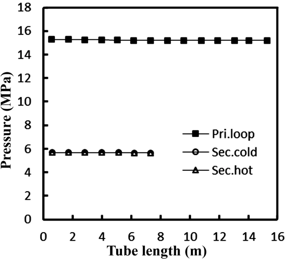
Fig.8.Fluid pressure in the primary and secondary loops under the 100%power.
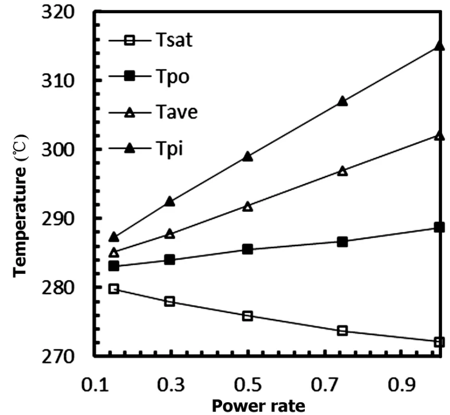
Fig.9.Fluid temperature in the primary and secondary loops under the 100%power rate.
Figure 7 displays the void fraction and the heat transfer coefficient along the tube lengths in the secondary loop.The coolant void fraction is higher in the hot side of secondary loop than that in the cold side given that the heat flux in the hot side is higher.However,the coolant void fractions that enter the steam room from both sides of the secondary loop are similar as a result of lateral mixing.
Figure 8 depicts the variation in the pressure of the primary and secondary loops.The pressure of the primary loop continually decreases in the ascending part but increases in the descending part with the increase in gravitational potential energy.The pressures are similar at both sides of the secondary loop and continue to progress downward along the tube length.

Fig.10.Variation in the circulation ratio and in circulation flow with power rate.

Fig.11.Void fractions inthe cold and hot channels of the secondary loop given different power.
Figure 9 displays coolant temperatures at five power rates in the primary and secondary loops.In the primary loop,inlet,outlet,and average coolant temperatures increase with the increase in power rate.The temperature of the inlet coolant increases more quickly than that of the outlet coolant.Hence, the variation amplitude of temperature in the primary loop increases with power rate.Fig.10 indicates that the saturation temperature of the coolant decreases when power rate increases.This finding suggests that the cooling capability of the secondary loop has been strengthened.
Figure 10 presents the variations in circulation ratio and in circulation flow with power rate with regard to the SG.With the increase in power rate from 15%to 100%,the SG circulation flow initially increases at the small power rate but decreases when the power rate exceeds 50%.This result is induced by the coupled effect of driving pressure and circulation resistance.As the boiling length in the secondary loop increases with increasing power rate,the void fraction and driving pressure increase as well.Moreover,the circulation resistance increases with increasing flow rate;hence,the circulation flows downward along the tube length.The circulation ratio continually increases with power rate,as shown in Fig.9.Furthermore,the mass flow of the vapor in the SG continually increases.

Fig.12.Enthalpy in the(a)primary and(b)secondary loops under different power rates.
Figure 11 shows the gaseous void fractions in both sides of the secondary loop at 75%,50%,30%and 15%power rates. This fraction increases along the tube lengths of both sides of the secondary loop.In addition,the gaseous void fraction is higher in the hot side than that in the cold side because boiling length is longer in the former.
Figure 12 depicts the variation in coolant enthalpy with tube length in the primary and secondary loops under15%–75%power rate.The coolant temperature in primary loop decreases along the tube length,where as that in the secondary loop is maximized.The enthalpy variation between the inlet and outlet of the two loops increases with high power rate.This result proves that the heat transfer process from the primary loop to the secondary loop is strengthened.In the secondary loop,coolant enthalpy increases more in the hot side than in the cold side.
VI.CONCLUSION
This study presents a steady-state thermal hydraulic code that was developed to thoroughly investigate the thermal hydraulic characteristics of the nuclear U-tube SG.This code is based on the two-zone geometry model of secondary loop. Thermal hydraulic analysis was conducted using the fourequation flux model,and a cross-iteration solution was established to meet the conditions of heat balance and natural circulation.This solution is based on the staggered grids and the first-order scheme of explicit–implicit difference.The steady state thermal hydraulic characteristics of the SG were thus identified using the developed code for the QINSHAN I PWR under 100%,75%,50%,30%and 15%power rates. Moreover,some important thermal and hydraulic parameters were identified for the primary and secondary loops.The results obtained under the100%power rate agree well with the results simulated using RELAP5.Hence,the established theoretical model and numerical scheme can guide the design and safe operation of a nuclear U-tube SG.
SYMBOL LIST
ρdensity,kg/m3;
uvelocity,m/s;
ttime,s;
zdistance,m;
henthalpy,kJ/(kgK);
Hheat transfer coef fi cient,W/(m2K);
qheat fl ux,W/m2;
qvvolume heat,W/m3;
ggravity,m/s2;
τwall shearing,Pa;
Uheat perimeter,m;
Deequivalent diameter,m;
ξresistance coef fi cient;
Φ2two-phase coef fi cient;
cpspeci fi c heat,J/(kgK);
Ttemperature,◦C;
rradius,m;
Ddiameter,m;
Across section,m2;
Wmass fl flow,kg/s;
αvoid fraction;
xsteam quality;
λconductivity,W/(m2K);
Hpressure head,Pa;
jg,critcritical super fi cial velocity,m/s;
Tsatsaturation temperature of secondary loop;
Tpooutlet temperature of primary loop;
Tpiinlet temperature of primary loop;
Taveaverage temperature of primary loop;
SUBSCRIPT
f liquid;
g gas;
p primary loop;
s secondary loop;
m mixture;
w wall;
b bubble;
tb Taylor bubble;
onb bubble onset;
i,jvolume index;
a acceleration;
c Form resistance;
SUPERSCRIPT
n,n+1 time step
[1]James C S and James K A.Nuel Eng Inter,1986,31,83–86.
[2]Moskal T E,Childerson M T,Carter H R.Amer Contr Conf, 1984,1:85–92.
[3]Heistand J W and Thakkar J G.ATHOS and FLOW3 simulation of the FRIGG heated rod bundle experiment,Technical Report NP-3541,EPRI,1984.
[4]Yetisir M,Pietralik J,Mirzai M.Pres Ves P,2003,2:61–69.
[5]Xue H J and Yan J Q.Nucl P Eng,1989,10:47–50.(in Chinese)
[6]Xie H,Zhang J L,Jia D N,et al.Nucl P Eng,1998,19:413–418.(in Chinese)
[7]Yu Y and Ju H M.J Tsinghua Univ(Sci&Tech),2004,44: 1202–1204.(in Chinese)
[8]Kazimi M and Massoud M.A condensed review of nuclear reactor thermal-hydraulic computer codes for two-phase fl ow analysis.Energy Laboratory Report No.MIT-EL 79-018, February 1980,37–40.
[9]IAPWS,Revised release on the IAPWS industrial formulation 1997 for the thermodynamic properties of water and steam [OL].Aug.2007,available at http://www.iapws.org.
[10]Taitel Y,Bornea D,Dukler A E.Aiche J,1980,26:345–354.
[11]Lockhart R W and Martinelli R C.Chem Eng Prog,1949,1: 39–48.
[12]Chen J C.Ind Eng Chem Proc DD,1966,5:531–535.
[13]Bergles A E and Rohsenow W M.J Heat Transf,1964,86: 365–372.
[14]NUREG/CR-5535/RevP3-VolIV,Relap5mod3.3codemanual volume IV:models and correlations,prepared for the Of fi ce of Nuclear Regulatory Research,US NRC,Washington DC, 2006,42.
10.13538/j.1001-8042/nst.25.050601
(Received December 3,2013;accepted in revised form March 3,2014;published online September 20,2014)
∗Supported by the National Natural Science Foundation of China(Nos. 51376065 and 51176052)
†Corresponding author,huangkai@ipp.ac.cn
猜你喜欢
杂志排行

Nuclear Science and Techniques的其它文章
- Dose rate distribution of photoneutrons in an ID beamline of SSRF:simulations and measurements
- Calibration method for electrode gains in an axially symmetric stripline BPM∗
- A study of quasi-absolute method in photon activation analysis∗
- High-resolution boosted reconstruction of γ-ray spectra∗
- A fractionation model based on three lognormal particle size distributions
- Model-predictive control of power supply for particle accelerators∗