Impacts of centrifuge errors on calibration accuracy of error model coefficients of gyro accelerometer*
2014-07-31ShimingWANGShunqingREN
Shi-ming WANG, Shun-qing REN
Space Control and Inertial Technology Research Center, Harbin Institute of Technology, Harbin 150080, China
Impacts of centrifuge errors on calibration accuracy of error model coefficients of gyro accelerometer*
Shi-ming WANG†, Shun-qing REN
SpaceControlandInertialTechnologyResearchCenter,HarbinInstituteofTechnology,Harbin150080,China
In order to study the impacts of accuracy centrifuge error on the coefficient accuracy of gyro accelerometer model, all error sources of centrifuge were analyzed. The impacts of centrifuge error sources on the coefficient calibrating accuracy of gyro accelerometer were discussed from the aspect of input specific force and angular rate relative to inertial space. Accurate expressions of input acceleration and input angular rate of tested accelerometer were obtained, error model coefficients were determined by using least square method and the impact degree of error sources on coefficient identification accuracy is evaluated in this paper. The relationships between some centrifuge errors and calibration accuracy of error coefficients of accelerometer were established and it builds a theoretical foundation for the calibrating accuracy of accelerometer to decide the accuracy of centrifuge.
Precision centrifuge, Gyro accelerometer, Input specific force, Homogeneous transformation, Error model coefficient
1.Introduction
Pendulous integrating gyro accelerometer (PIGA) is a kind of gyro accelerometer that uses gyroscopic couple for feedback[1-3]. It is valuable due to the high accuracy, wide dynamic range and automatic integration and it is a major part of high accuracy inertial navigation system. The high accuracy of inertial navigation system leads to an increasing demands on accuracy of gyro accelerometer. Calibration accelerator with an input of 1g, under gravity, could no longer meet the demand any more. Higher input acceleration is always expected to calibrate the higher error coefficient and other data of gyro accelerometer[4-5]. Therefore, centrifuge experiment is commonly used to provide acceleration input of gyro accelerometer. To improve test accuracy of gyro accelerometer, centrifuge with counter-rotating platform is commonly used for effective shield of translational motion caused by centrifuge angular rate and for filtering gyro disturbance torque at the direction of outer ring principal axis of gyro accelerometer. However, during the process of testing, calibration accuracy of gyro accelerometer was often affected by centrifuge error, which leads to a certain difference between theoretical value and measured result of accelerometer output[6]. The impact of centrifuge error on calibrating accuracy of gyro accelerometer was comprehensively analyzed in this paper.
2.Centrifuge testing experiment of gyro accelerometer
When Calibrating gyro accelerometer on centrifuge, angular rate of centrifuge will make gyro accelerometer perform translational motions which create additional gyro disturbance torque at the direction of outer frame rotating axis of gyro accelerometer and lead to output error of gyro accelerometer. Centrifuge with counter-rotating platform could be used to eliminate such effect, as shown in Figure 1.
In Figure 1, “1” represents the principle axis of centrifuge; “2” represents the vector rate of angular rate of principal axis of counter-rotating platform’s rotorΩ;ωis vector rate of angular rate of counter-rotating platform. During the testing process, angular rateωof counter-rotating platform at test end and vector rateΩof principle axis are equal and opposite under ideal situation, i.e.,ω=-Ω.
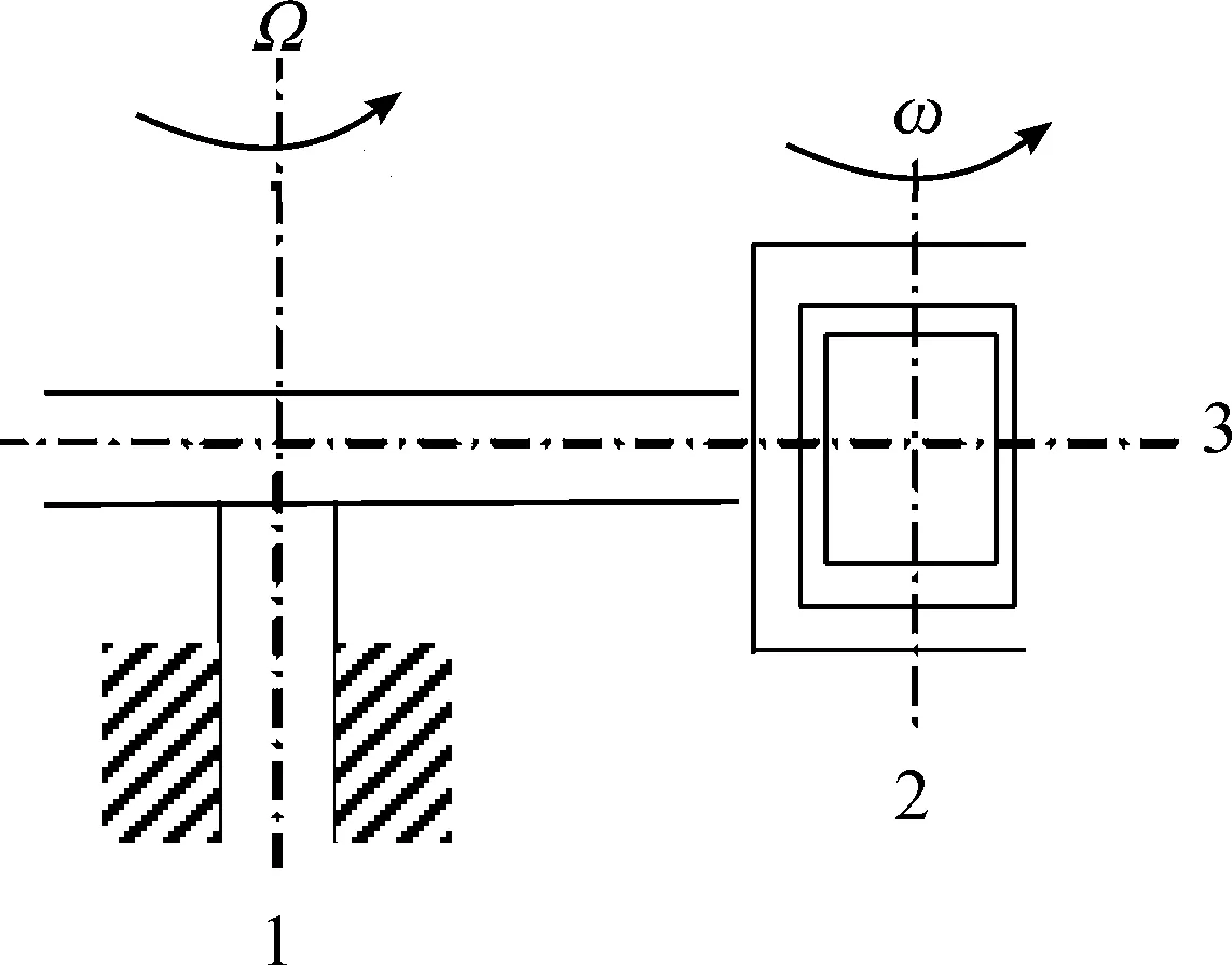
Figure 1.Schematic diagram of precision centrifuge with counter-rotating platform
According to reference[1], acceleration at the direction of input axis of accelerometer could be decomposed from acceleration at the direction of input axis of centrifuge:
(1)
Where,φ0refers to initial phase-angle between positive direction of input axis and the direction of centripetal accelerationO2O1at the beginning of the test.
3.Error model of gyro accelerometer
Error model of gyro accelerometer is:
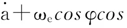
(2)
Where,αrefers to output angular rate;airefers to input acceleration at the direction of input axis of gyro accelerometer;K0refers to bias;K1refers to scale factor;K2refers to second-order nonlinear error coefficient;K3refers to cubic term error model coefficient;εrefers to the residual error;ωecosφrefers to north component of geographic angular rateωeof the earth and its component at output angular rate’s direction of gyro accelerometer isωecosφcosφe0, in whichφrefers to local latitude,φ0refers to initial phase-angle between gyro accelerometer and geographic north angular rate of the earthωecosφat the beginning of the test; ΔΩrefers to the difference between angular rate of principle axis and counter-rotating platform’s angular rate, i.e.,ω=-(Ω+ΔΩ).
4.Centrifuge error sources that affect calibration accuracy of gyro accelerometer
Based on the Eq.(1), impacts of centrifuge error sources on calibrating accuracy of gyro accelerometer could be first seen on the input specific force which mainly includes radius accuracy of centrifuge and principle axis angular rate accuracy. Meanwhile, distribution of centripetal acceleration and gravitational acceleration on the input axis of accelerometer that caused by such factors as centrifuge pose error and installation error will affect calibration accuracy of accelerometer. In addition, factors like pose error and installation error also affect angular rate of relative inertia space of centrifuge and thus affect calibration accuracy of gyro accelerometer. Therefore, radium error, angular rate error and pose error are the major centrifuge errors that affect calibration accuracy of gyro accelerometer. Impacts from these errors will be thoroughly analyzed as follows.
4.1.The establishment of the coordinate system
Structure diagram and the establishment of the coordinate system are shown in Figure 2.o0x0y0z0is geographic coordinate system;o1tx1ty1tz1tis principle axis axle sleeve coordinate system;o1x1y1z1refers to principle axis coordinate system;o2tx2ty2tz2trefers to horizontal axle sleeve coordinate system;o2x2y2z2refers to horizontal coordinate system;o3tx3ty3tz3trefers to azimuth axle sleeve coordinate system;o3x3y3z3refers to azimuth axis coordinate system;o4x4y4z4refers to working base plane coordinate system;o5x5y5z5refers to accelerometer coordinate system.
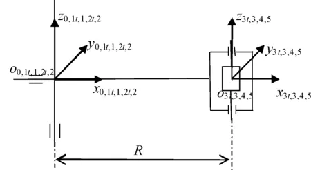
Figure 2.Coordinate systems of centrifuge
4.2.Analysis of centrifuge error sources that affect input specific force
4.2.1.Static error sources
Static error sources of centrifuge mainly include installation error of principle axis axle sleeve Δθx1tand Δθy1t; perpendicularity Δθy2tand intersection degree Δy2tbetween horizontal axis and principle axis, radium static error ΔRS, perpendicularity Δθy3tand intersection degree Δy3tbetween horizontal axis and azimuth axis, initial zero error Δθx3tof azimuth axle sleeve, perpendicularity Δθx4and Δθy4between working base plane and azimuth axis, accelerometer’s installation base plane pose error Δθx5and Δθy5, eccentricity error Δx5and Δy5, initial zero error Δθz5etc[7-8]. It needs to be pointed out that installation error of accelerometer is not a source of centrifuge error but it will affect error coefficient calibration accuracy of accelerometer and this is the reason why it is considered here. All static error sources and homogeneous matrix between adjacent coordinate systems which are given by error sources and nominal pose are shown in Table 1. In this table,Lrepresents the distance between origino4of azimuth axis coordinate system and working base plane.lrepresents the distance between origino5of accelerometer coordinate system and working base plane.
4.2.2.Dynamic error sources
Centrifuge dynamic errors mainly include principle axis’s runouts Δx1(Ωt) and Δy1(Ωt), axial float Δz1(ωt), wobbles Δθx1(Ωt) and Δθy1(Ωt), radius dynamic error ΔRd, horizontal axis’s runouts Δy2(β) and Δz2(β), axial float Δx2(β), wobbles Δθy2(β) and Δθz2(β), azimuth axis’s runouts Δx3(γ) and Δy3(γ), axial float Δz3(γ), wobbles Δθx3(γ) and Δθy3(γ) etc.Ωtrepresents angle caused by rotation around principle axis,βrefers to angle caused by rotation around horizontal axis,γrefers to angle caused by rotation around azimuth axis. All dynamic error sources and homogeneous matrix between adjacent coordinate system, given by error sources and nominal pose, are shown in Table 2.
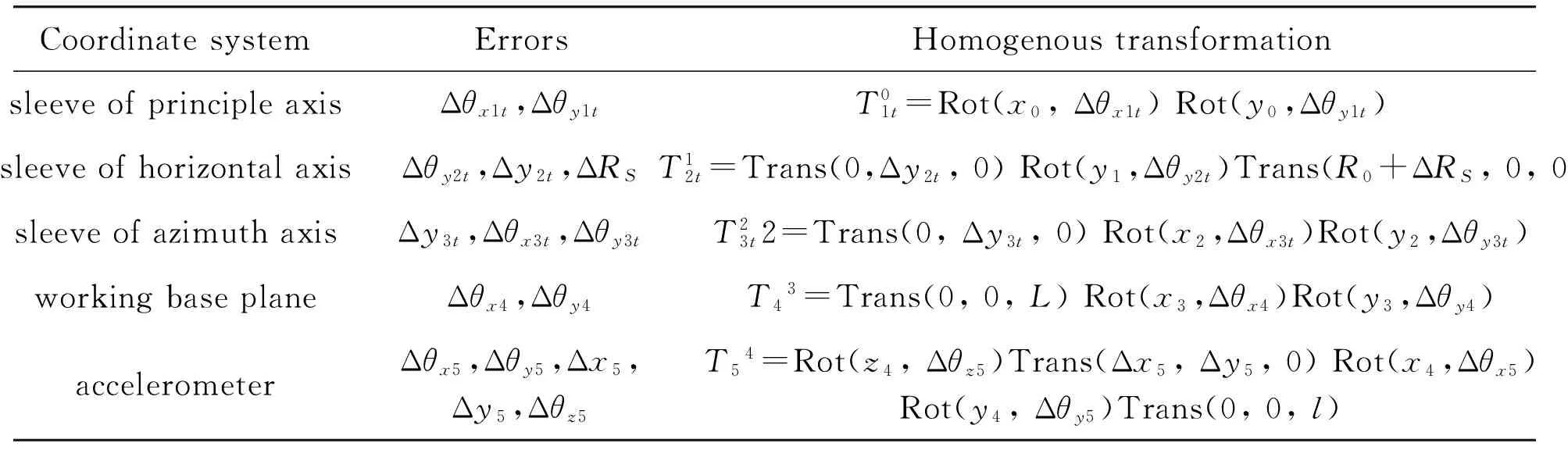
Table 1.Coordinate systems and homogeneous transformations relative to static errors of centrifuge
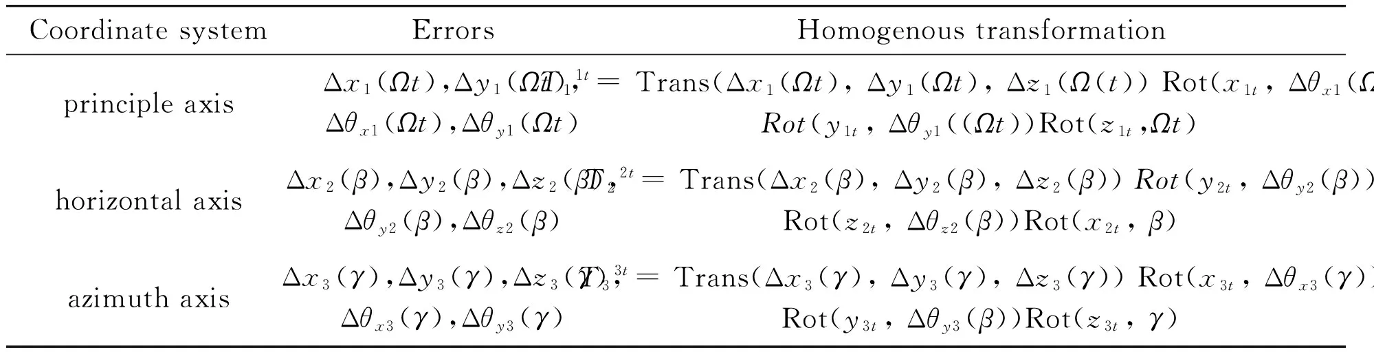
Table 2.Coordinate systems and homogeneous transformations relative to dynamic errors of centrifuge
Radius static error and dynamic error are integrated here,R=R0+ΔR, in which, ΔR=ΔRS+ΔRd,R0refers to static radium nominal value. According to homogeneous transform in Table 1 and Table 2, homogeneous matrix between accelerometer coordinate system and geographic coordinate system could be expressed as follows:
(3)

(4)
This can be used to calculate gravitational acceleration’s component along each axis of coordinate system, as shown in Eq.(5):
(5)
Gravitational acceleration’s componentaIgon input axis of under-test accelerometer is:
(6)
The unit isg.
Adopting second derivative inTsfor Eq.(4), acceleration absolute of origin of accelerometer coordinate system in principle axis coordinate systemo1x1y1z1could be expressed as follows:
(7)
Neglecting second-order infinitesimals during the process of calculation, and averaging with full-cycle integration, the acceleration component on each axis of accelerometer coordinate system could be obtained:
(8)
Therefore, the componentaIωof centripetal acceleration on input axis of accelerometer could be expressed as:
(9)
Where,γ=-Ωt+φ0,φ0refers to the initial phase-angle between positive direction of input axis of accelerometer and the direction of centripetal accelerationO2O1at the beginning of the test, and the other parameters are defines as follows:
In addition, operation of centrifuge is also affected by Coriolis acceleration. So, the gyro accelerometer’s input specific force expression which contains the centrifuge error could be obtained as follows:
(10)
4.3.Analysis of error sources that affect angular rate of inertial space
In fact, pose error of centrifuge also affects angular rate. In case of in-motion counter-rotating platform, as shown in Figure 1, if taking the impact of pose error on accelerometer’s input angular rate into consideration, the corresponding homogeneous matrix could be obtained:
(11)
When pose changes, angular rate distribution on each axis of gyro accelerometer is:
(12)
Where,
Angular rate of gyro accelerometer’s input axis is:
(13)
5.Impacts of all error resources on calibration accuracy of gyro accelerometer
This paper mainly studied the impacts of all error resources on each error coefficient of gyro accelerometer with influence from centrifuge and gave one-to-one corresponding relationship between error resource and error coefficient.K1in error model of gyro accelerometer can be calibrated with an input of 1g gravitational field. Here,K1is set to be known during the testing process.
Substitute Eq.(10) into Eq.(2), the error model of gyro accelerometer with error item could be obtained and the error model can be simplified as Eq.(14):
Δx2(β)+Δx3(γ)+ΔR)/R0]cosγ+
[(-Δy2t-Δy3(γ)-Δy3t-Δy2(β))/R0+
Δθz5+Δθz2(β))]sinγ-Δx5/R0}R0(Ω+
Δω)2/g+(-Δθy3t-Δθy3(γ)-Δθy2t-
Δθy2(β))cosγ+Δθx3t+Δθx3(γ))sinγ-
Δθy4-Δθy5-2ωRΩvsinφ/g〉+
K2[R0(Ω+Δω)2/gcosγ]2+
K3[-R0(Ω+Δω)2/gcosγ]3
(14)
(15)
Substitute Eq.(14) into Eq.(15), setA=R(ω+Δω)2/gandψ=π, then one could get:
ΔR)/R0]+Δθy3t+Δθy3(γ)+Δθy2t+
Δy3(γ)-Δy3t-Δy2(β))/R0+Δθz5+
Δθz2(β))]+Δθx3t+Δθx3(γ))}cosφ0+
(AΔx5/R0+Δθy4+Δθy5+2ΩRΩvsinφ/g)〉+
ωecosφcosφe0-ΔΩ
(16)
Eq.(16)couldbesimplifiedasfollows:
K2Z2+K3Z3
(17)
Where,
ΔR)/R0]+Δθy3t+Δθy3(γ)+Δθy2t+
Δy3(γ)-Δy3t-Δy2(β))/R0+Δθz5+
Δθz2(β))]+Δθx3t+Δθx3(γ))}cosφ0-
(AΔx5/R0+Δθy4+Δθy5+2ΩRΩvsinφ/g)
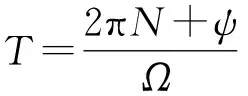
Therefore, when some certain amounts of inputs (say n) of gyro accelerometer which are over 1gare given, least square method could be adopted to calculate each error coefficient, as shown in Eq.(18):
(18)
Where,
SetA=5, 10, 15, 20, 25, 30 (put Δωaside inA, that isA=Ω2R/g, setgper unit), each error coefficient of accelerometer in case of error item included could be evaluated, set calibration radiumR0to 2.5 m, centrifuge running time to 450 s. Angular rate corresponding to input acceleration andφ0data when 450 s run out were shown in Table 3.
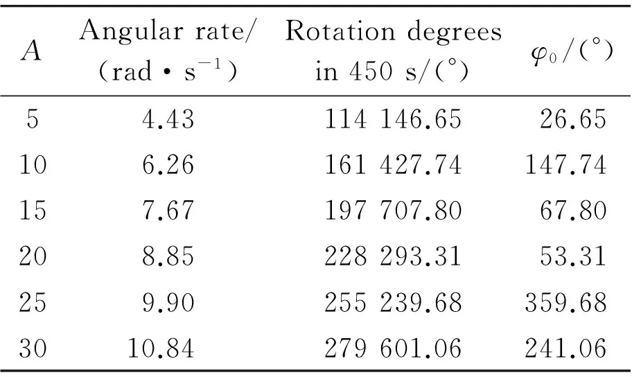
Table 3. Inputs of tested accelerometer with corresponding φ0
In order to observe the impacts of all error items on accelerometer error coefficient, take conclusion in chapter 4.1 into consideration, all error coefficients in Eq.(17) were set to:K0=0.061 973 ^/s,K1=505.209 7 ^/g/s,K2=0.02 ^/g2/s,K3=0.003 ^/g3/s。
1) Calculate influence of pose errors on error coefficient, set each pose error item to 1(10-5rad and use Eq.(18) to calculate all pose errors’ independent impact on each error coefficient. The specific results are shown in Table 4.
In Table 4, taking Δθz5as an example, its impact on calibration accuracy of gyro accelerometer is analyzed, which affects output accuracy of accelerometer. Impact of Δθz5onK3is 1×10⁻⁵^/g3/s. Acceleration input of centrifuge is set to be 20g. Then, the impact on accelerometer output could be obtained:
As obtained from the above calculation, error item Δθz5has a larger impact on gyro accelerometer and it should be fixed on actual calibration. This method can be used to calculate impact of other error items on output of gyro accelerometer. Based on the calculation, we could find out that each error affects output of accelerometer to varying degrees. This should be fixed in an actual calibration of accelerometer’s parameter.
2) Analyze impact of speed accuracy on error coefficient of gyro accelerometer, expression of centripetal acceleration can be modified as follows:
(19)
Suppose the accuracy of angular rate Δωis 0.5×10⁻⁶rad/s, and substitute Eq.(19) into Eq.(18), all the error coefficients of model could be acquired by only considering the accuracy of angular rate. Here are:
3) Discuss impact of pose error on angular rate’s accuracy which affects error coefficient calibration accuracy of gyro accelerometer. Pose error that affects accuracy of angular rate is displayed in Table 5. Take all poses impact into consideration and calculate its impact on corresponding error coefficient accuracy of accelerometer.
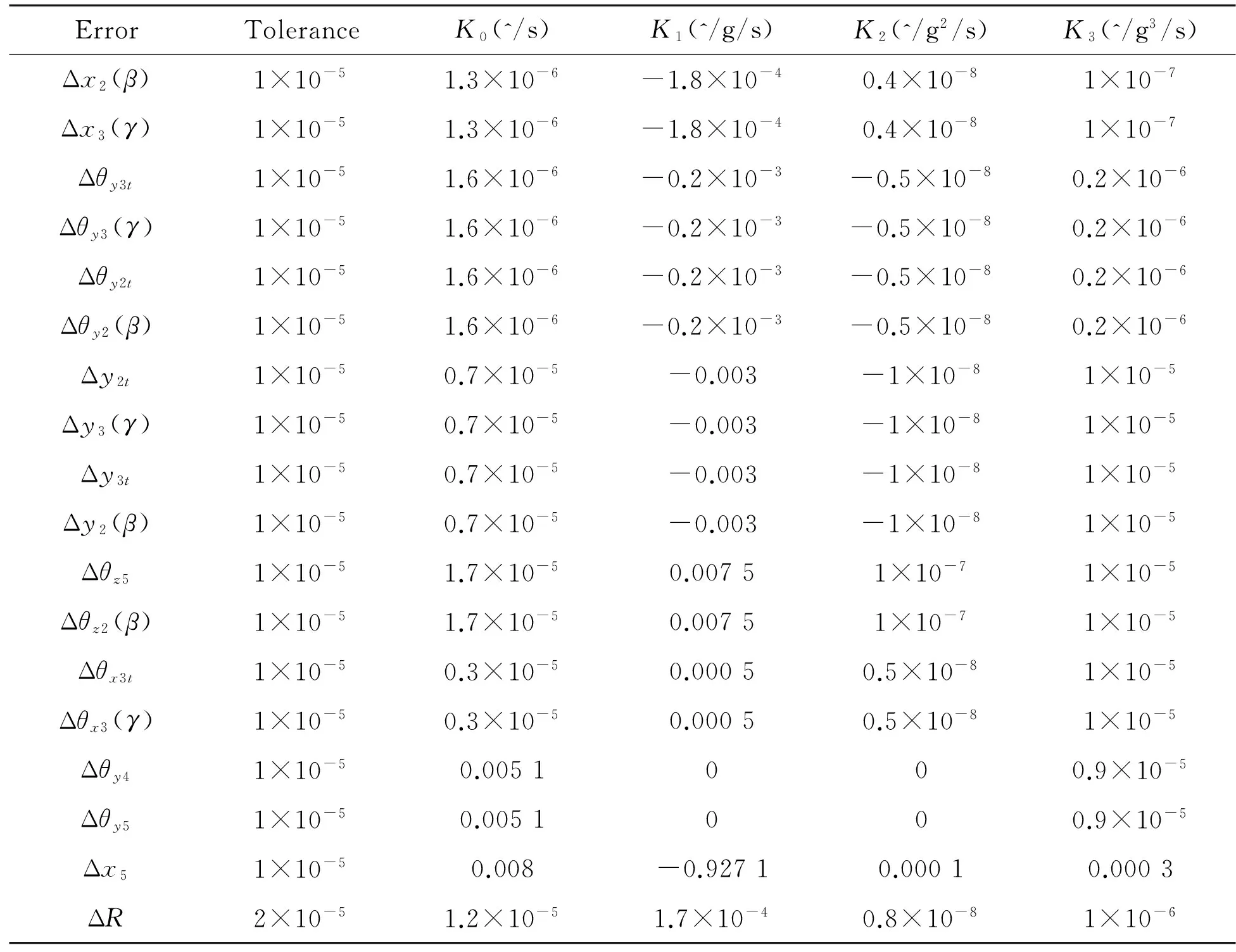
Table 4. Single impact of pose error on the calibration accuracy of error model coefficients
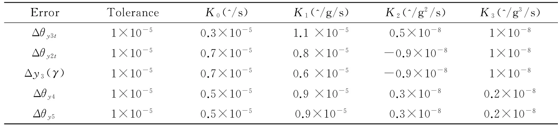
Table 5. Impacts of centrifuge errors through angular rate on calibrating accuracy of error model coefficients
6.Conclusion
1) All possible error sources that affect calibration accuracy of gyro accelerometer during the process of experiment and complete error model with all error resources are obtained in this paper.
2) Least square method was used to calculate and discuss impacts of all error resources on each error model coefficient. Therefore, the relationship between calibration error of accelerometer and centrifuge error was determined.
3) Eq.(18) was used to amend and re-identify error model coefficient after gyro accelerometer identified it in accordance with input calibration and output, which will improve identification accuracy of error model coefficients.
[1] WANG Shi-ming,REN Shun-qing.Calibration accuracy of error model coefficients K2 and K3 of gyro accelerometer influenced by errors of centrifuge[J].Nanotechnology and precision Engineering,2013,11(2):140-145.
[2] Wu Wenxin,Error analysis of gyro accelerometer tested on precision centrifuge[D].Harbin:Harbin Institute of Technology,2011.
[3] WANG Shi-ming,REN Shun-qing.Relationship between calibration accuracy of error model coefficients of accelerometer and errors of precision centrifuge[J].Journal of Astronautics,2012,33(4):520-526.
[4] Std 836TM-2009,IEEE Recommended Practice for Precision Centrifuge Testing of Linear Accelerometers[S].The Institute of Electrical and Electronics Engineers.
[5] Lu Yuan,Cheng Xianghong.Random misalignment and lever arm vector online estimation in ship borne aircraft transfer alignment[J].2014,47(1):756-764.
[6] Xing Hai-feng.Research on the influence of the errors of precision centrifuge on the model coefficients calibrating error of the measured accelerometers[D].Harbin:Harbin Institute of Technology,2009.
[7] Li Dan-dong.The test method research of high precision quartz accelerometer[D].Harbin:Harbin Institute of Technology,2011.
[8] WU Sai-cheng,QIN Shi-qiao,WANG Xing-shu,et al.Systematic calibration method for RLG inertial measurement unit[J].Journal of Chinese Inertial Technology,2011,19(2):185-189.
离心机误差对陀螺加速度计误差模型系数标定精度的影响*
王世明†, 任顺清
哈尔滨工业大学 空间控制与惯性技术中心, 哈尔滨 150080
为了研究精密离心机自身误差对陀螺加速度计模型系数标定精度的影响,分析了离心机各个误差源,从输入比力和相对惯性空间角速率两个方面讨论了离心机误差源对加速度计参数标定的精度影响,给出了被试加速度计输入加速度和角速度的精确表达式。应用最小二乘法对误差模型参数进行辨识,且计算了在各误差源作用下对于参数辨识精度的影响程度。根据仿真结果,找出了某些离心机误差对加速度计误差系数标定的影响关系,为按照加速度计的标定精度来确定离心机的精度打下了理论基础。
精密离心机;陀螺加速度计;输入比力;齐次变换;误差模型系数
TB934
2014-03-10
10.3969/j.issn.1001-3881.2014.12.002
*Project supported by Twelfth Five-year Pre-research Project (No.51309050202)
† Shi-ming WANG, PhD. E-mail: wangshi_8845@163.com
猜你喜欢
杂志排行

机床与液压的其它文章
- A Simple time-domain method for bearing performance degradation assessment*
- Structural design and performance testing of the electromagnetic proportional pressure relief valve
- Design of special fixture for automatic measurement of resistance of auto ignition wire*
- Tool wear monitoring based on wavelet packet coefficient and hidden Markov model*
- Interior ballistic simulation and parameter influence analysis of an underwater pneumatic launcher*
- Influence of airflow uniformity over the duct outlet of vehicle air-condition on cooling performance*