Comparative Study of Two Carbon Fiber Cathodes and Theoretical Analysis in Microbial Fuel Cells on Ocean Floor
2014-04-20FUYubinLIUYuanyuanXUQianLUZhikaiandZHANGYelong
FU Yubin, LIU Yuanyuan, XU Qian, LU Zhikai, and ZHANG Yelong
Institute of Materials Science and Engineering, Ocean University of China, Qingdao 266100, P. R. China
Comparative Study of Two Carbon Fiber Cathodes and Theoretical Analysis in Microbial Fuel Cells on Ocean Floor
FU Yubin*, LIU Yuanyuan, XU Qian, LU Zhikai, and ZHANG Yelong
Institute of Materials Science and Engineering, Ocean University of China, Qingdao 266100, P. R. China
Cathode activity plays an important role in the improvement of the microbial fuel cells on ocean floor (BMFCs). A comparison study between Rayon-based (CF-R) and PAN-based carbon fiber (CF-P) cathodes is conducted in the paper. The two carbon fibers were heat treated to improve cell performance (CF-R-H & CF-P-H), and were used to build a new BMFCs structure with a foamy carbon anode. The maximum power density was 112.4 mW m−2for CF-R-H, followed by 66.6 mW m−2for CF-R, 49.7 mW m−2for CF-P-H and 21.6 mW m−2for CF-P respectively. The higher specific area and deep groove make CF-R have a better power output than with CF-P. Meanwhile, heat treatment of carbon fiber can improve cell power, nearly two-fold higher than heat treatment of plain fiber. This improvement may be due to the quinones group formation to accelerate the reduction of oxygen and electron transfer on the fiber surface in the three phase boundary after heat treatment. Compared to PAN-based carbon fiber, Rayon-based carbon fiber would be preferentially selected as cathode in novel BMFCs design due to its high surface area, low cost and higher power. The comparison research is significant for cathode material selection and cell design.
microbial fuel cells on ocean floor; carbon fiber cathode; heat treatment; power density; theoretical analysis
1 Introduction
Microbial fuel cells (MFCs) convert chemical energy into electrical energy by the catalytic activity of microorganisms (Berk et al., 1964; Rao et al., 1976; Davis and Yarbrough, 1962; Higgins et al., 2011; Nimje et al., 2012). Substrate which is oxidized by bacteria, generates electrons and protons at the anode. Electrons are transferred through an external circuit while the protons diffuse through the solution to the cathode, where electrons combine with protons and oxygen to form water (Cheng et al., 2006). The microbial fuel cell on ocean floor or benthic microbial fuel cell (called BMFC for short in the paper) is a special type of MFC (Fu et al., 2011). The BMFC consists of an anode imbedded in marine sediment, and is connected by an external circuit to a cathode positioned in overlying seawater. It can generate useful power in remote environments to supply for small monitor and vehicle continuously (Lowy and Tender, 2008). However, the application of BMFC has been limited due to its low power density. A number of factors can affect BMFC performance (Niessen et al., 2004). But most researches for improving power density are mainly focused on the anodic part with the cathodic compartments less studied, and in most BMFCs the cathodic reaction is abiotic, which typically is the reduction of oxygen (Rhoads et al., 2005).
Using oxygen as the electron accepter has many advantages, such as a high thermodynamic redox potential, good self-sustaining operation, and ready availability (Zhao et al., 2006). The reduction of oxygen at the cathode is one of the major bottlenecks of BMFCs. Past researches mainly focused on chemical catalysis of this oxygen reduction by using noble metal compound. The authors used Pt and CoTMPP as catalysts on the cathodes, the maximum power density of MFC being 379±5 mW m−2and 369±8 mW m−2respectively (Cheng et al., 2006); but the noble metal catalyst greatly hinders the wide application of MFC. Biocathodes have been developed based on enrichment of bacteria for oxygen reduction. Clauwaert et al. combined the anode of an acetate oxidizing tubular MFC with an open air biocathode for electricity production. The maximum power production was 83± 11 W m−3(0.183 L MFC) for batch-fed systems (20−40% Coulombic yield) and 65 ±5 W m−3for a continuous system with an acetate loading rate of 1.5 kg COD m−3day (90%±3% Coulombic yield) (Clauwaert et al., 2007). However, few researches about the BMFCs cathode have been conducted so far, and different cathodic materials play an important role in increasing the BMFCs power output.
Carbon fi ber (CF) is a kind of material with high specific surface area that has been used as electrode (Zhao et al., 2008; Wei et al., 2011), especially PAN-based car-bon fiber (CF-P) electrode has been widely used in all kinds of cells (Yanga et al., 2010; Hasvold et al., 1997). But few researches have been conducted on the Rayon-based carbon fiber (CF-R), though it has higher surface area, excellent adsorption capabilities and deep groove structure. Furthermore, it is relatively inexpensive. In this paper, these two kinds of CFs were treated with a high temperature process (CF-P-H & CF-R-H), and were used to build BMFCs having a new structure with a foamy carbon anode, respectively. The surface morphologies of the two CFs were observed by scanning electron microscope (SEM), and the properties were measured by polarization curves and power density curves. BMFC with CF-R-H cathode showed better performance than with CF-P-H cathode. A novel theoretic analysis is given to explain a synergistic effect of three phase boundary model and quinones catalytic mechanism on the reduction of oxygen and electron transfer.
2 Materials and Methods
2.1 Electrode Materials
Carbon fibers were used as received (without pretreatment, CF-R & CF-P, Qingdao Yuanhui Composite Material Co., LTD), heated in air (CF-R-H & CF-P-H). All fibers are weighed about 10 g with surface area of about 110 cm2. CF-R-H and CF-P-H were treated in a muffle furnace at 440℃ and 463℃ for 30 min respectively (seen in TG-DTG curves). A foamy carbon (5.5 cm thick, 12 cm × 6 cm in size, pore diameter > 1 mm, Qingdao Gaotai New Material Co., LTD) was used as the anode. Foamy carbon has a large surface area because of the porousness (1−2 mm). Only one foamy carbon was used as the anode to ensure that the four types of CFs cathodes are in the identical environment.
2.2 BMFCs Building
BMFCs were constructed by using CF-R, CF-P, CF-RH and CF-P-H as cathodes respectively and a foamy carbon as anode. The cell was a cuboid container (72 cm × 30 cm × 35 cm) filled with marine sediment and seawater. The depth of the marine sediment was 20 cm, and the depth of the seawater was 15 cm. The distance from the cathode to the interface between marine sediment and seawater was 13 cm. The cell discharge was conducted by putting an external load in its circuit. Fig.1 illustrates the cell configuration; these BMFCs operated at room temperature.

Fig.1 BMFC configuration.
2.3 Analytical Measurements
Thermogravimetric analysis (TG) and differential thermogravimetric analysis (DTA) were carried out using a model ZRY-2P instrument in air at a heating rate of 2℃min−1. Surface morphologies of different cathodes were observed by scanning electron microscope (S-4800, HITACHI) and the specific surface area of CFs was characterized by Micromeritics ASAP 2020 surface area and porosity analyzer. For the determination of the power output, a resistor box (ZX-21, Shanghai Precision & Scientific Instrument Co., Ltd.) was applied as an external load. Cathode potential during cell polarization was monitored by using a saturated calomel electrode (SCE) placed in seawater. Polarization curves were obtained by measuring the stable cathode potential generated at different external resistances.
3 Results
3.1 Heat Treatment of Carbon Fibers
TG-DTA curves (Fig.2a) of CF-R show that the weight of CF-R significantly reduces at 440℃. This may suggest that the weight loss of CF-R occurs. This temperature is chosen to be the heat treatment temperature of CF-R. In the same way TG-DTA curves (Fig.2b) of CF-P show that the heat treatment temperature of CF-P is 463℃.

Fig.2 TG-DTA curves of Rayon-based (a) and PAN-based carbon fiber (b).
Table 1 shows that the weight and resistance of different cathodes decrease after heat treatment. It may becaused by the removal of the impurities on the surface of CFs. Most impurities are lipids which are non-conducting so that the resistance of CFs decreases after heat treatment.
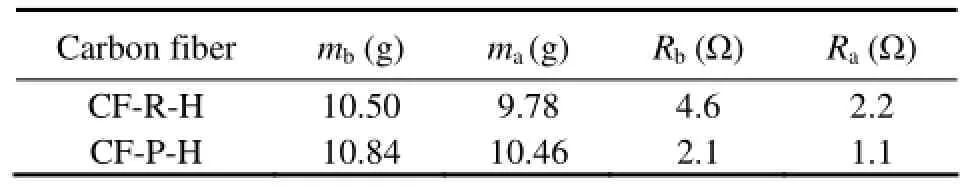
Table 1 Weight and resistance changes of different carbon fibers
3.2 Surface Morphologies of Different Cathodes
SEM analysis indicates that the surface groove of carbon fiber increases and becomes deeper after heat treatment. Previous studies showed that the specific surface area was in proportion to the amount of surface groove (Wang et al., 2010). Here, heat treatment causes the specific surface area and surface roughness to increase. The differences of the surface grooves shown in Fig.3 indicate that the specific surface area of CF-R-H, CF-R, CF-P-H and CF-P increases in turn.

Fig.3 Surface morphology of untreated and treated carbon fibers taken by scanning electron microscope.
3.3 Specific Surface Area of CFs
The test results of specific surface area are shown in Table 2. The specific surface area of CFs increases after heat treatment, but the surface areas of CF-P and CF-P-H are less than that of CF-R. The CF-R-H has the maximum specific surface area of 644 m2g−1. Specific surface area is proportional to the reduction rate of oxygen on cathode. Heat treatment causes the increase in specific surface area, being beneficial to cathodic property.

Table 2 Specific surface area of CFs
3.4 Electrochemical Behavior of Different Cathodes
The cathodic polarization curves are shown in Fig.4. As expected, the open circuit potentials of the four cathodes are similar. However, the cathodic polarization curves of the four cathodes are much different: when the current densities > 48 mA m−2, the cathode potentials of CF-R-H, CF-R, CF-P-H, CF-P reduce in turn. These phenomena indicate that the anti-polarization ability of carbon fibers increases after heat treatment. The performance of cathode material depends on: conductivity, specific surface area, porosity and surface clearness (Kazuya, 2008). As Table 1 and SEM pictures show, the conductivity and specific surface area of the two types of carbon fiber all increase after heat treatment. The specific surface area of CF-P increases after heat treatment, even though it is much lower than CF-R. High conductivity can accelerate the electron transfer, and high specific surface area can make cathode contact a greater amount of oxygen to consume more electrons. Thus the anti-polarization ability increases in the following order: CF-R-H, CF-R, CF-P-H and CF-P.
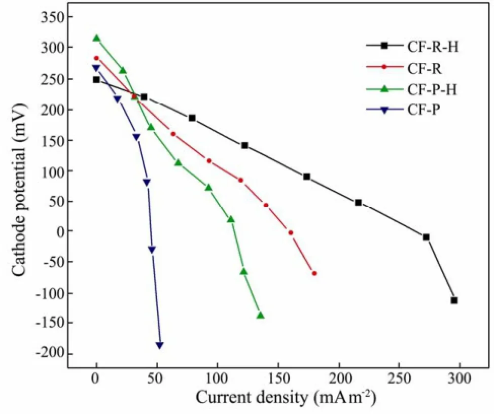
Fig.4 Cathodic polarization curves for the different cells.
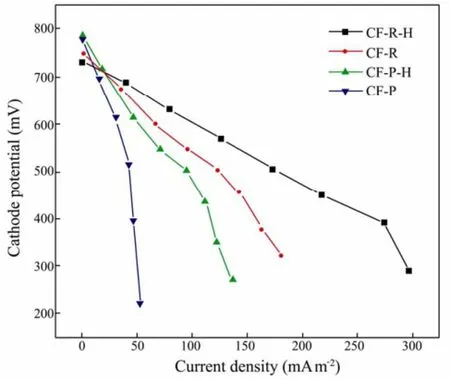
Fig.5 Polarization curves for the different cells.
Base on the slopes of the BMFCs polarization curves (Fig.5), the inner resistances of the different BMFCs are: 112 Ω for the CF-R-H cathode, 179 Ω for CF-R, 278Ω for CF-P-H and 635Ω for CF-P. Fig.6 indicates that the maximum power densities are 112.4 mW m−2(CF-R-H), 66.6 mW m−2(CF-R), 49.7 mW m−2(CF-P-H) and 21.6mW m−2(CF-P) respectively. The power density of CFR-H cathode is 1.7 times higher than that of CF-R, and the power density of CF-P-H is 2.3 times greater than that of CF-P. These changes of resistances imply the power density increases with the decreasing of resistances. It’s clear that better performance can be attributed to the lower resistance of the BMFCs.
Fig.6 Power density curves of four BMFCs.
The performance of CF-R is better than that of CF-P from above discussion. Although the strength of CF-R is a little bit lower than that of CF-P, it has higher specific surface area. The maximum power output obtained from the power density curves is 112.4 mW m−2, which is much different from the other kinds of MFC with higher power density because marine sediment and seawater in BMFC are original, rather than artificial ones.
4 Theoretical Analysis
In BMFC, electrons, protons and oxygen all meet at cathode in a tri-phase reaction (cathode, air, and water) as Fig.7 shows. The area of tri-phase reaction dominates the performance of cathode, and the tri-phase reaction increases along with the length of the three-phase line (Gunther et al., 1997; Xu et al., 1999). In other words, the power density of BMFCs and the reaction rate on cathode increase with the length of the three-phase line. SEM images confirm that after heat treatment the surface groove of CFs becomes deeper and wider, and specific surface area increases accordingly. Thus, the three-phase line gets longer after heat treatment as Fig.8 shows.

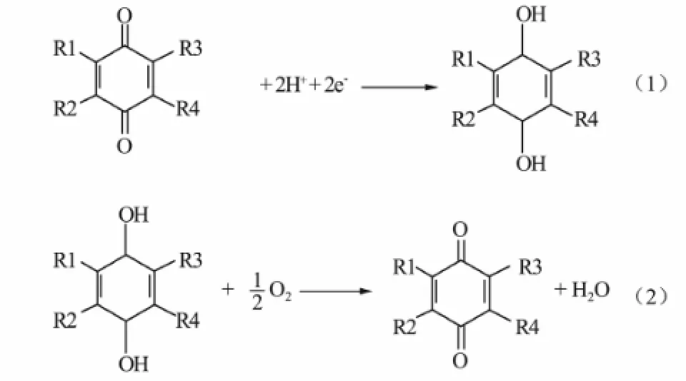
Fig.7 Three phase boundary of the solid (a), gas (b), and liquid phase (c) in accomplishing oxygen reduction: 2H++ 2e-+ 1/2O2→ H2O.

Fig.8 Three phase boundary change of CF cathode after heat treatment.
On the other hand, we think that different surface molecular structure would play an important role in oxygen consumption and electron transfer. Researches have reported that the O/C ratio decreases after heat treatment (Wang et al., 2009). This occurs due to a decrease in the oxygen content by converting C–O to C=O. The oxidation (C–O to C=O) results in a decrease in the O-content, and therefore the decrease in the ratios of C–O/O (increase in C=O/O) (Fenga et al., 2010). The increase in the ratios of C=O/O is possibly because that the CFs surface generates quinones after heat treatment. Quinones are able to mediate electron transfer to electron acceptors such as Fe3+, Cu2+and hexacyanoferrate (Freguia et al., 2009). Eqs.1 and 2 show the reaction process, they accelerating the electron transfer and reduction of oxygen respectively.
In summary, the larger tri-phase reaction zone contributes to the diffusion of oxygen, and surface quinone groups help to perform its consumption and electron transfer. The synergistic effect improves the performance of CF-R-H cathode. Therefore, if different molecules on the carbon fibers could be artificially assembled, it would be beneficial to improve cathode performance. Further researches will be conducted in this respect.
5 Conclusions
Rayon-based carbon fiber has better performance than a PAN-based one in BMFCs. Their maximum power densities are 112.4 mW m−2(CF-R-H), 66.6 mW m−2(CF-R), 49.7 mW m−2(CF-P-H) and 21.6 mW m−2(CF-P) respectively; heat treatment increases the density of CF-R-H 1.7-fold higher than that of CF-R, and the density of CF-P-H more than 2-fold higher than that of CF-P. Cell anti-polarization is obtained for CF-R-H and CF-P-Hcathodes. A novel mechanism implies that longer three phase boundary line improves O2supply, and more quinoid groups after heat treatment accelerate the reduction of oxygen and electron transfer. The Rayon-based carbon fiber therefore offers a better selection of material in BMFCs.
Acknowledgements
This work was support by the Key Project of Nature Science Fund of Shandong Province, China (ZR2011B Z008), and the Special Fund of Marine Renewable Energy from China’s State Oceanic Administration (GHME 2011GD04).
Berk, R. S., and Canfield, J. H., 1964. Bioelectrochemical energy conversion. Applied and Environmental Microbiology, 12: 10-12.
Rao, J. R., Richter, G. J., Von Sturm, F., and Weidlich, E., 1976. The performance of glucose electrodes and the characteristics of different biofuel cell constructions. Bioelectrochemistry and Bioenergetics, 3: 139-150.
Davis, J. B., and Yarbrough, H. F., 1962. Preliminary experiments on a microbial fuel cell. Science, 137: 615-616.
Higgins, S. R., Foerster, D., Cheung, A., Lau, C., Bretschger, O., Minteer, S. D., Nealson, K., Atanassov, P., and Cooney, M. J., 2011. Fabrication of macroporous chitosan scaffolds doped with carbon nanotubes and their characterization in microbial fuel cell operation. Enzyme and Microbial Technology, 48: 458-465.
Nimje, V. R., Chen, C.Y., Chen, H. R., Chen, C. C., Huang, Y. M., Tseng, M. J., Cheng, K. C., and Chang, Y. F., 2012. Comparative bioelectricity production from various wastewaters in microbialfuelcells using mixed cultures and a pure strain of Shewanella oneidensis. Bioresource Technology, 104: 315-323.
Cheng, S. A., Liu, H., and Logan, B. E., 2006. Power densities using different cathode catalysts (Pt and CoTMPP) and polymer binders (Nafion and PTFE) in single chamber microbial fuel cells. Environmental Science and Technology, 40: 364-369.
Fu, Y. B., Zhao, Z. K., Liu, J., Li, K. Z., Xu, Q., and Zhang, S. Y., 2011. Sulfonated polyaniline/vanadate composite as anode material and its electrochemical property in microbial fuel cells on ocean floor. Science China Chemistry, 54: 844-849.
Lowy, D. A., and Tender, L. M., 2008. Harvesting energy from the marine sediment-water interface III Kinetic activity of quinone and antimony-based anode materials. Journal of Power Sources, 185: 70-75.
Niessen, J., Schroder, U., Rosenbaum, M., and Scholz, F., 2004. Fluorinated polyanilines as superior materials for electrocatalytic anodes in bacterial fuel cells. Electrochemistry Communications, 6: 571-575. Rhoads, A., Beyenal, H., and Lewandowski, Z., 2005. Microbial fuel cell using anaerobic respiration as an anodic reaction and biomineralized manganese as a cathodic reactant. Environmental Science and Technology, 39: 4666-4671.
Zhao, F., Harnisch, F., Schroeder, U., Scholz, F., Bogdanoff, P., and Herrmann, I., 2006. Challenges and constraints of using oxygen cathodes inmicrobial fuel cells. Environmental Science and Technology, 40: 5193-5199.
Clauwaert, P., Ha, D. V. D., Boon, N., Verbeken, K., Verhaege, Rabaey, M. K., and Veratraete, W., 2007. Open air biocathode enables effective electricity generation with microbial fuel cells. Environmental Science and Technology, 41: 7564-7569.
Zhao, F., Rahunen, N., Varcoe, J. R., Chandra, A., Avignone-Rossa, C., Thumser, A. E., and Slade, R. C. T., 2008. Activated carbon cloth as anode for sulfate removal in a microbial fuel cell. Environmental Science and Technology, 42: 4971-4976.
Wei, J. C., Liang, P., and Huang, X., 2011. Recent progress in electrodes for microbial fuel cells. Bioresource Technology, 102: 9335-9344.
Yanga, H., Tub, H. C., and Chiang, I. L., 2010. Carbon cloth based on PAN carbon fi ber practicability for PEMFC applications. International Journal of Hydrogen Energy, 35: 2791-2795.
Hasvold, O., Henriksen, H., Melvaer, E., Citi, G., Johansen, B. O., Kjonigsen, T., Galetti, R., 1997. Sea-water battery for subsea control systems. Journal of Power Sources, 65: 253-261.
Wang, L. Y., Yang, C. L., Lu, Y. G., Liu, X., and Zhang, Y. X., 2010. Effect of electrochemical treatment on surface characters of PAN-based carbon fibers. Aerospace Materials Technology, 3: 51-54.
Kazuya, W., 2008. Recent developments in microbial fuel cell technologies for sustainable bioenergy. Journal of Bioscience and Bioengineering, 106: 528-536.
Gunther, G. S., 1997. Interfacial aspects in the development of polymer electrolyte fuel cells. Solid State Ionics, 94: 249-257.
Xu, H. F., Han, M., and Yi, B. L., 1999. Cathode mathematical model of proton exchange membrane fuel cell. Journal of Power Sources, 23: 312-315.
Wang, X., Cheng, S. A., Feng, Y. J., Merrill, M. D., Saito, T., and Logan, B. E., 2009. Use of carbon mesh anodes and the effect of different pretreatment methods on power production in microbial fuel cells. Environmental Science and Technology, 43: 6870-6874.
Fenga, Y. J., Yanga, Q., Wanga, X., and Logan, B. E., 2010. Treatment of carbon fi ber brush anodes for improving power generation in air-cathode microbial fuel cells. Journal of Power Sources, 195: 1841-1844.
Freguia, S., Masuda, M., Tsujimura, S., and Kano, K., 2009. Lactococcus lactis catalyses electricity generation at microbial fuel cell anodes via excretion of a soluble quinone. Bioelectrochemistry, 76: 14-18.
(Edited by Ji Dechun)
(Received September 25, 2012; revised March 8, 2013; accepted March 13, 2013)
© Ocean University of China, Science Press and Springer-Verlag Berlin Heidelberg 2014
* Corresponding author. Tel: 0086-532-66781690
E-mail: ffyybb@ouc.edu.cn
杂志排行

Journal of Ocean University of China的其它文章
- Wave Effect on the Ocean Circulations Through Mass Transport and Wave-Induced Pumping
- A Study of Transport and Impact Strength of Fukushima Nuclear Pollutants in the North Pacific Surface
- Annual and Interannual Variability of Scatterometer Ocean Surface Wind over the South China Sea
- A Method for Sea Surface Wind Field Retrieval from SAR Image Mode Data
- Sedimentary Characteristics of Relict Deposits on the Western South Yellow Sea
- Use of Different Mooring Models on Global Response Analysis of an Innovative Deep Draft Platform