Phase-Lock technology of full digital UPS based on DSP*
2014-03-09YajingZHANGGuoxuZHANG
Ya-jing ZHANG,Guo-xu ZHANG
Department of Information Engineering,Tangshan College,Tangshan 063000,China
Phase-Lock technology of full digital UPS based on DSP*
Ya-jing ZHANG†,Guo-xu ZHANG
Department of Information Engineering,Tangshan College,Tangshan 063000,China
In order to avoid a big impact on load when the UPS inverter is sw itching,the output voltage of UPS invertermust be consistentwith the grid voltage in frequency and phase domain.Fast and reliable software phase-locked tracking technology can accurately provide the standard sinusoidalvoltage for the digital inverter with the same frequency and phase as those of the grid voltage.This paper mainly discusses the phase-locked technology of full digital UPS based on TMS320LF2407.
DSP,UPS,Phase-lock
*Project supported by Science and Technology Bureau of Tangshan(No.12110215a)
† Ya-jing ZHANG,E-mail:50513835@qq.com
1.Introduction
UPS(uninterrupted power supply)can provide reliable and stable power for load nomatter whatever the power grid is normal or abnormal.UPS is used for key loads such as computer rooms,hospital,and so on[1-3].These workplaces need UPS to provide the important devices when the power break down.The traditional on-line UPS is very complex and expensive since,because ofmany power parts and analog controllers are in the UPS.Therefore,people have paid more and more attentions on the study of full digital UPS,which is more reliable and more suitable for the development of modern science and technology[4].Digital control technology is simpler and more stable than analog control technology.With the development of microelectronic technology,the full digital UPS including advanced control strategies became a reality since,more andmore solutions about power electronics technology have arisen[5-7].
In this paper,we willmainly discuss the phaselocked technology,which is one of key technologies in a full digital UPS based on TMS320LF2407.
The phase-locked technology plays a very important role in many fields such as communication,radar,navigation,space technology and computer.There are two parts in phase-locked technology,i.e.,analog and digital.There are some defects for in analog phase-locked technology inmany respects that includes reliability,stability and integration;digital phase-locked technology includes two parts,one is digital logic phase-locked whichthat ismade of digital logic device, the other is software phase-locked which isthat based on DSP[8].Digital logic phaselocked circuit has ve only two statues:turn-on and cut-off.As compared with analog phase-locked technology,digital logic phase-locked technology has ve lots of advantages in terms of noise immunity,integrated level and reliability.It also can eliminate adverse effects in circuit that is caused by loop filter and phase detector’s DC shift.But in digital logic phase-locked loop,we need to transfer analogy electric level to square pulse or discrete data,so it will be much difficult than before for the system analysis and design.Software phase-locked technology can be used for the design of phase-locked loop,which has all the advantages in digital logic phase-locked technology.In addition,it can increase integration and intelligence of system and simplify the hardware circuit,and it is easily tomodify or extend aswell.
2.The importance of phase-locked
When UPS runs,there are two switches in working process:one is at the moment when the power starts,bypass supplies power to the load,the inverter operates no-load.At the same time,phase-locked function gets started to adjust the inverter’s output to trace the power frequency and phase.When they are the same,the inverter will begin to supply power to the load.The other is at themomentwhen the inverter circuit goes wrong or the load arises fluctuation.The control system will block PWMoutput to stop the inverter,at the same time the switch of bypass will get connected,the load will be supplied directly by grid voltage[5].
In order to avoid too much impact on the load when the switch isworking,the power frequency and phase of output voltage from UPS inverter must be consistentwith grid voltage.Therefore,phase-locked technology is very necessary in UPS system.Software phase-locked technology is one of the key parts in digital UPS system because the fast and reliable software phase locking technology can supply normal voltage sinusoidal wave to inverter which has the same frequency and phase with grid voltage.
3.The fundamental princip le of phaselocked loop
PLL(phase-locked loop)is a closed-loop phase-controlled system,which can follow the frequency and phase of input signal automatically.PLL consists of phase comparator,low pass filter(LPF)and voltage controlled oscillator(VCO).The block diagram of control is shown in Figure 1.
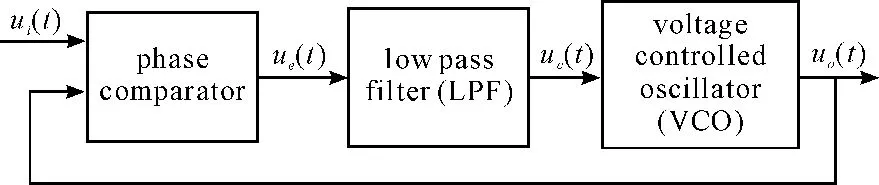
Figure 1.The block diagram of phase-locked control process
Following is the working principle of PLL.Two signals with different frequency and phase will be sent into the phase comparator,one is the output of VCO uo(t),the other is the sampled signal of grid voltage ui(t).Therefore,an error signal ue(t)will be produced.The amplitude of error signal is directly proportional to the phase difference between uo(t)and ui(t).ue(t)will be processed by LPF,then it will send out a control voltage signal uc(t),which is the average value of ue(t).VCO will adjust the frequency and phase of output voltage signal uo(t)under the control of uc(t),so that the difference of frequency and phase between uo(t)and ui(t)will get gradually decreased.
4.Phase-locked technology of on line UPS
Because the control circuit of single phase UPS inverter will produce the SPWM wave in different ways,so there exist significant differences in phaselocked controlmethod.
4.1.Analog phase-locked technology of on line UPS
As shown in Figure 1,the phase-locked control diagram of traditional online UPS is presented,its diagram of phase-locked control is shown in Figure 1.When the power supply is at normal situation,the detection circuit of grid voltage will send a high level signal and,50 Hz grid voltagewill isbe converted into a single-polarity invertible full wave rectification signal by the waveform transformation circuit.Then the signalwill be sent to the inputof analog switch 1,after it passeding the analog switch 2,a bunch of grid voltage synchronization signal will occur.The output of frequency transformerwill be is synchronizeding by following the signal with 20 ms periods,so the grid voltage synchronization signal which is addeding to the control port ofmultivibrator can adjust the phase of high frequency pulse from high frequency oscillator and,to ensure that the sine wave generator could an output50 Hz reference sinusoidalwave.The frequency and phase will be always synchronized with the grid voltage due to the phase-locked synchronization circuit(PLL).When the power supply is at abnormal situation,multivibrator will send out a signal whose local frequency is 20 kHz and output 500 Hz pulse train by frequency divider.Finally a normal sine wave will occur with the stable frequency at 50 Hz by sine wave generator.
4.2.Digital phase-locked technology of on line UPS
Digital phase-locked technology of on line UPS uses themicroprocessor as the core control chip and applies the software method to lock phase.The circuit consists of AC voltage transformer,precision rectifier circuit,zero-crossing comparator,low-pass filter,inverter,analog switch and microprocessor.The block diagram of this circuit is shown in Figure 3.
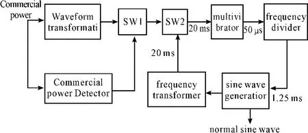
Figure 2.Phase-locked control diagram of online UPSwith output transformer

Figure 3.The diagram of digital phase-locked control circuit in online UPS
Following is theworking principles is as follows.Grid AC voltage is insulated and reduced to be a low voltage AC signal whosewhich frequency and phase areis the same as grid voltage by using potential transformer and,it will be is sent to the precision rectifier circuit.The output is a positive polarity half wave rectifier signal,tomeasure amplitude of voltage by using A/D converter.The voltage will be is also sent to zero comparator.The output is the polarity of AC voltage,and it will be sent to microprocessor by using I/O.Therefore,we can get the real-time wave data about external AC voltage.By using the data and D/A converter,we can get sine wave.Because there are lots of harmonic waves in grid voltage,the output of potential transformer is not a normal sine wave,so the output ofmicroprocessor is not normal sine wave as well.
Therefore,we can use digital low-pass filter to filter the higher frequency harmonic waves after the PWMoutput to ensure that the output is stable and clear enough.
Following is the working process.PWM(pulsewidth modulation)circuit in microprocessor ismodulated by digit sequence to produce a square wave pulse that is proportional to signal amplitude.Ifmicroprocessor uses crystal oscillator whose frequency is of 20 MHz,and the resolution of output from PWM circuitwill be is8 bits and then the highest frequency of output square wave will be 78 kHz.We can use a RC low pass filter with minor integration constant addeding to the output of PWM circuit’s output to produce a smooth halfwave output.This signal itwill be sent to analog switch directly,at the same time it will be sent to inverter circuit as well.The output is negative polarity half wave voltage and,this voltage will be sent to the same analog switch.Themicroprocessorwill control the two signalswith opposite polarity output in turn by switching the working status of analog switch.Thus a sine wave with the same frequency and phase at grid voltage will be produced.When the commercial power is failed,the microprocessor can use the normal 50 Hz sinusoidal sequence stored in memory to control the output of inverter.
4.3.Software phase-locked technology of on line UPS
With the development of microelectronic technology,there have been many special microprocessors that is used formotor control with high cost-efficiency,which integrates PWM generation circuit in its own chip and can adjust the output frequency of PWM wave by software programming.Software phase-locked control technology in UPS is based on this kind of microprocessors,which can change the frequency by programming.
There are two kinds ofways by software.One is that both the grid voltage and inverter output voltage are needed to be filtered and shaped,and then they will be changed to square wave with the same frequency.Capture pins on microprocessor will catch the rising edge of this square wave,which will be used to calculate the frequency and phase difference and the result could be used to adjust the frequency of SPWM to ensure that the frequency and phase of grid voltage and inverter output voltage will be kept as the same.
The second method is that only grid voltage will be filtered and shaped and then it will change the square wave with the same frequency.Capture pins on microprocessor will catch the rising edge of this square wave to cause an interrupt,then it will judge whether the phase of SPWMoutput is earlier or later than the phase of grid voltage.The result will be used to adjust the frequency of the next SPWMoutput by changing the time of timer.Therefore,the frequency will be exactly tracked.
The above two methods have many things in common.We assume that the frequency of grid voltage is 50 Hz,then we divide each voltage cycle into N equal parts according to the carrier frequency of SPWM(for example,if the carrier frequency is 78 kHz,then N is 150).The corresponding sinusoidal quantity are stored in memory of microprocessor as the list,N remains constant in each SPWM time,we can adjust the output frequency by adjusting the frequency of carrier.The implementation depends on two interrupts:one is the interrupt of SPWM carrier timer and the other is the interrupt of capture.
Since there exist two methods that the output of inverter could lock the phase of grid voltage by adjusting the frequency of SPWM,the steady accuracy of track is better than the dynamic accuracy of track.When PLL startsworking,the tracing velocity will be very low,so the speed of synchronous response still remains to rise and their anti-jamming and fault-tolerance remain to rise too.
4.4.Program flow of phase-locked loop
The program flow of phase-locked is shown in Figure 4.Notice that when the frequency and phase of power is tracked,the speed can not be too fast because it could effect the outputwaveform and the stabilitywill be destroyed.In this paper,themethod we used is similar with fuzzy control.When we detect that the frequency of input is higher(or lower)than the provided value,we will increase(or decrease)the value of PWM time-meter according to the step until the frequency of output fall into the normal range.We can use the same method to adjust the phase.According to the testing result,the method has been proved that it is simple and convenient,furthermore,it is easy to control and the error is smaller in output between the PPL and the power.
According to the above method,we can calculate the speed of tracking:when f is50 Hz and it remains constant,we only need to adjust the phase,so the speed Vp will be:


Where,Ph is the error of phase between the output voltage and grid voltage.
When the frequency f is out of the tracking range,i.e.,from 47 Hz to 53 Hz,the speed of adjustment frequency Vf is:


Figure 4.The program flow of phase-locked loop
5.Conclusion
The phase-locked technology of full digital UPS based on TMS320LF2407 has been thoroughly discussed in this paper.It has been shown that the precision of full digital phase-locked technology ismuch higher and easier to implement and it could meet all the requirements about phase-locked technology of UPS.
[1] ZHANG Yu,CHENG Xin.Software Phase Locked Technology Based On DSP2812[J].Power Electronics,2008(2):75-77.
[2] HE Daokun,XU Wei,WANG Wei.Design Of Phase Locked Loop[J].Research and Exploration In Laboratory,2013(2):239 -242.
[3] CUI Jiefan,SHAN Baoyu,Qinchao.Harmonic Analysis And Optimization Strategy Of Minimum Switch Losses SVPWM[J].Machine Tool& Hydraulics,2013(9):55-58.
[4] HUANGWei,WU Qian.Fuzzy-PID Control Of Parameter Based Auto-Tuning And Its Application[J].Machine Tool& Hydraulics,2013(6):81 -86.
[5] LIU Yangbin,Ouyang Mingsan.Research Of Mining Flameproof DC System Based On DSP[J].Coal Mine Machinery,2010(8):167 -170.
[6] WANGWei,ZHANG Zhiwen,LUOWenfu.Tracking Frequency Based On All Digital Phase-Locked Loop In Power System[J].Power Electronics,2010(2):89 -91.
[7] HOUWeimin,JIANG Jinghong,ZHANG Cheng.Design On Digital Phase Locked Loop Based On FPGA[J].Microcomputer Applications,2008(8):95 -98.
[8] CHEN Rui,WANG Yanming,WANG Yanyan.Simulation And Realization Of All Digital PPL[J].Digital Technology and Application,2012(7):33 -36.
基于DSP的全数字UPS逆变器锁相控制技术*
张雅静†,张国旭
唐山学院信息工程系,河北唐山 063000
为保证不间断电源逆变器交直流切换过程不对负载产生过大的冲击,UPS逆变输出电压必须与电网电压的频率及相位保持一致。快速可靠的软件锁相跟踪技术可以准确地为逆变器数字化控制提供与电网电压同频同相的标准正弦电压。主要讨论基于TMS320LF2407数字化控制平台的全数字不间断电源中的锁相控制技术。
DSP;UPS;锁相
TM571
10.3969/j.issn.1001-3881.2014.12.016
2014-02-05
猜你喜欢
杂志排行
机床与液压的其它文章
- Adaptive dynamic optimization design of machining center pillar*
- Design of special fixture for automatic measurement of resistance of auto ignition wire*
- Intelligent automobile pedal controller based on CAN bus
- Design and calculation of welding positioning mode for cross beam*
- Research of data acquisition process and reconstruction for constructing prototype surface*