Application of modified k-ω model to predicting cavitating flow in centrifugal pump
2013-06-22HoulinLIUDongxiLIUYongWANGXianfangWUJianWANG
Hou-lin LIU*, Dong-xi LIU, Yong WANG, Xian-fang WU, Jian WANG
Research Center of Fluid Machinery Engineering and Technology, Jiangsu University, Zhenjiang 212013, P. R. China
Application of modified k-ω model to predicting cavitating flow in centrifugal pump
Hou-lin LIU*, Dong-xi LIU, Yong WANG, Xian-fang WU, Jian WANG
Research Center of Fluid Machinery Engineering and Technology, Jiangsu University, Zhenjiang 212013, P. R. China
Considering the compressibility of the cavity in the cavitating flow, this paper presents a modifiedk-ωmodel for predicting the cavitating flow in a centrifugal pump, in which the modifiedk-ωmodel and Schnerr-Sauer cavitation model were combined with ANSYS CFX. To evaluate the modified and standardk-ωmodels, numerical simulations were performed with these two models, respectively, and the calculation results were compared with the experimental data. Numerical simulations were executed with three different values of the flow coefficient, and the simulation results of the modifiedk-ωmodel showed agreement with most of the experimental data. The cavitating flow in the centrifugal pump obtained by the modifiedk-ωmodel at the design flow coefficient of 0.102, was analyzed. When the cavitation number decreases, the cavity initially generates on the suction side of the blade near the leading edge and then expands to the outlet of the impeller, and the decrease of the total pressure coefficient mainly occurs upstream of the impeller passage, while the downstream remains almost unaffected by the development of cavitation.
modifiedk-ωmodel; cavitation model; centrifugal pump; experimental investigation
1 Introduction
In liquid flows, if the pressure drops below the saturated vapor pressure, the liquid will change its thermodynamic state by forming vapor-filled cavities. This phenomenon, generally associated with undesired effects, is known as cavitation. It can cause significant reduction in performance, as manifested by the reduced mass flow rates in pumps, load asymmetry, noise, vibration, and erosion. To avoid or minimize cavitation, detailed knowledge about the existence, extent, and behavior of cavitation is indispensable during the initial design stage. Nowadays, computational fluid dynamics (CFD) plays a major role in conducting inner flow field analyses in the early design process, and the advanced commercial CFD software can be used for a wide range of flow, such as the cavitating flow (Liu et al. 2010; Wang et al. 2011).
In recent decades, the methods of cavitation simulation based on the Navier-Stokes equations have received increasing attention due to their superiority in physical modeling andcomputational capabilities for cavitation problems. These methods are largely divided into two main categories: interface tracking methods (Liu et al. 2006) and homogeneous flow models (Coutier-Delgosha et al. 2003a; Singhal et al. 2002; Zwart et al. 2004; Schnerr and Sauer 2001).
The RANS method based on the homogeneous flow theory along with an additional transport equation for vapor volume fraction was used in this study. The mass transfer between vapor and liquid due to cavitation was modeled by a cavitation model. Therefore, the key to numerical simulation was the establishment of an appropriate turbulence model and a cavitation model. It is important to note that these methods assume that vapor and liquid phases are incompressible, and that they have the same instantaneous velocity field and pressure field. However, several recent studies have found that the cavitating flow in the mixed-phase region is locally compressible (Coutier-Delgosha et al. 2002; Wu et al. 2003, 2005; Sezal et al. 2006). In addition, the standard two-equation turbulence models (e.g., thek-ωclass), originally developed for single-phase non-cavitating flows, are limited to predicting the cavitating flow.
According to the factors described, this paper presents a modifiedk-ωmodel for predicting the cavitating flow in a centrifugal pump, in which the modifiedk-ωmodel and Schnerr-Sauer cavitation model were combined with ANSYS CFX. The standard and modified turbulence models were verified by the numerical predictions, which were executed with three different values of the flow coefficient, and then the numerical results were compared with the experimental data. Finally, the cavitating flow in the centrifugal pump obtained by the modifiedk-ωmodel at the design flow coefficient of 0.102 was analyzed in detail.
2 Mathematical models
2.1 Governing equations
The governing equations for mass and momentum of a mixture are
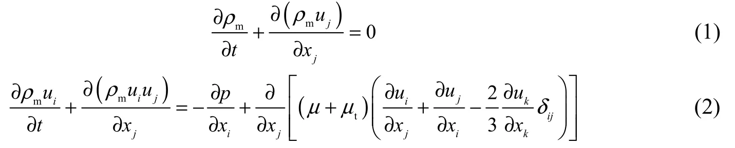
whereuis the velocity;tis the timeδijis the Kronecker number;ρmis the mixture density;μandμtare the mixture dynamic viscosity and turbulent viscosity, respectively; andpis the pressure. The liquid-vapor mass transfer due to cavitation is governed by the vapor volume fraction transport equation:
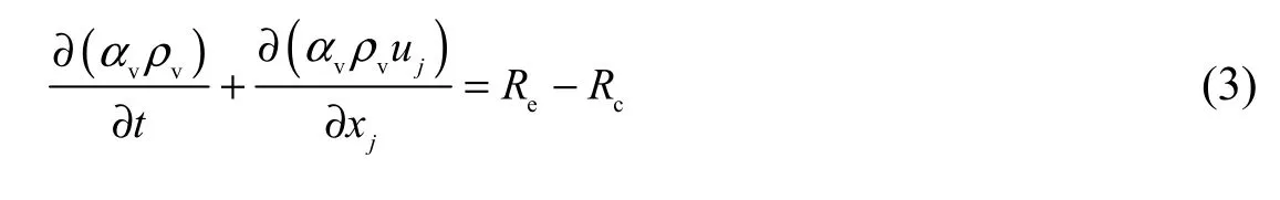
whereρvis the vapor density;αvis the vapor volume fraction; andReandRcare th e mass transfer rates related to the evaporation and condensation in cavitation, respectively.
The mixture densityρmand the mixture dynamic viscosityμare defined as
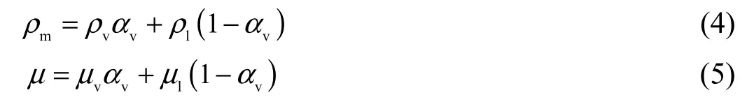
whereρlis the liquid density, andμvandμlare the vapor viscosity and liquid viscosity, respectively.
2.2 Turbulence model
The widely appliedk-ωmodel was adopted (Wilcox 2006). Taking the compressibility of the cavity in the cavitating flow into account, an improvement was made to thek-ωmodel by modifying the formula ofμtfollowing the idea of Coutier-Delgosha et al. (2003b). However, in the modified method, the expressions and the constants of the turbulence kinetic energy (k) and specific dissipation rate (ω) equations are unchanged.
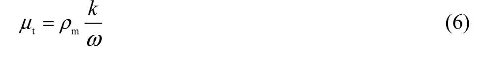
The formula for the turbulent viscosityμtin the standardk-ωmodel is
The modified formula forμtis
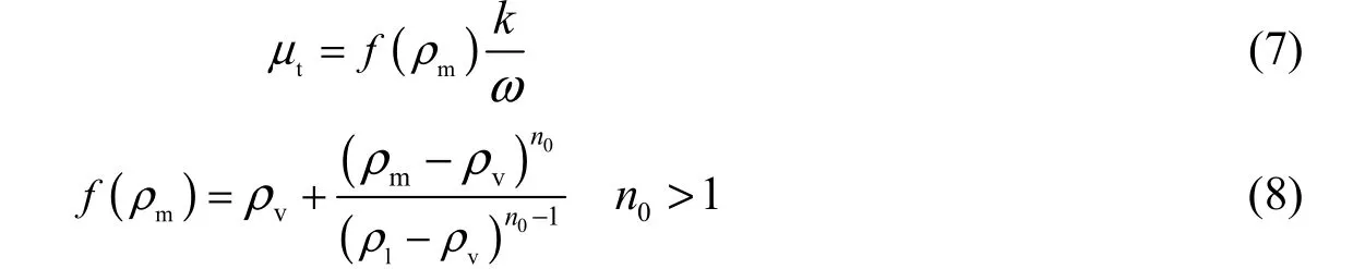
As can be observed in Eqs. (6) through (8), for the cavitating flow, the use off(ρm) observably decreases the turbulent viscosity in the flow field with a high vapor volume fraction. Nevertheless, for the non-cavitating liquid flow, the formula ofμtfollows the original form. The exponentn0was set as 10 in this study.
2.3 Cavitation model
The Schnerr-Sauer model, frequently used for the cavitating flow in hydrofoils, propellers, and axial-flow pumps (Frikha et al. 2009; Li 2011; Sato et al. 2009; Olsson 2008), was introduced in this study, and its applicability in the centrifugal pump was validated. The Schnerr-Sauer model is expressed as
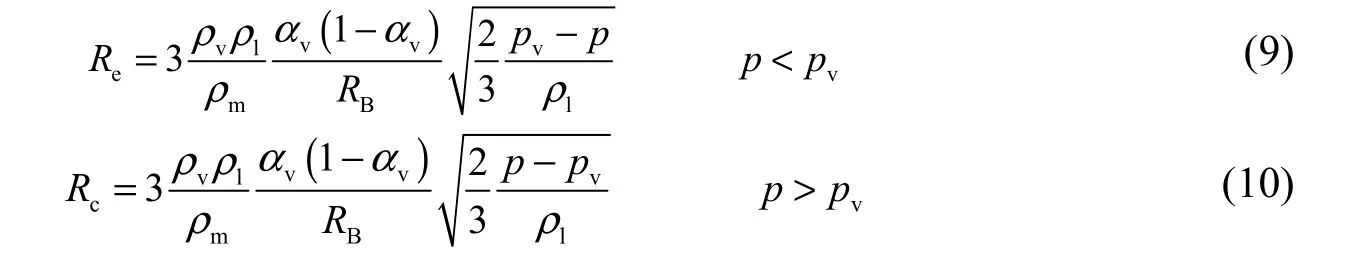
The radius of bubblesRBcan be computed by
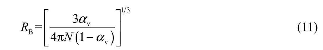
wherepvis the vapor pressure, andNis the number of vapor bubbles per unit volume of liquid.
The mass transfer rates in the model are proportional toαv(1−αv). They approach zero whenαv=0 orαv=1, and reach maximum values at a certain value ofαvwithin the range of 0 to 1.Nis the only parameter that needs to be confirmed in this model. Extensive validation studies suggest that the optimal value ofNis in the neighborhood of 1013(Li et al. 2008).
3 Simulation setup
3.1 Geometry and grid
The parameters of a pump used for cavitating flow simulation are as follows: the design flowQis 0.013 9 m3/s; the rotation speednis 2 900 r/min; the specific speednsis 99; the impeller radiusD2and base volute radiusD3are 0.168 m and 0.18 m, respectively; the outlet angleβ2is 31°; the blade numberZis 5; and the impeller outlet widthb2and volute inlet widthb3are 0.01 m and 0.02 m, respectively.
The flow domain included four sub-domains: the impeller, the volute, and the prolongations for the impeller inlet and volute outlet, which are used to reduce the influ ence of the large velocity gradient on computational results. The three-dimensional models of the pump were produced by the professional software Pro/E, with the gap between the impeller and volute being added to the impeller.
It is important to note that ANSYS CFX uses the CV-FEM (control volume-finite element method) method, and the CV-FEM method has a better performance with the hexahedral mesh than with the tetrahedral one, which tends to degrade the computing efficiency. In addition, smoothing the tetrahedral mesh may highly degrade the local quality of the mesh (Pierrat et al. 2008). Therefore, the hexahedral mesh generated by ICEM CFD was used in this study.
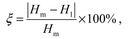
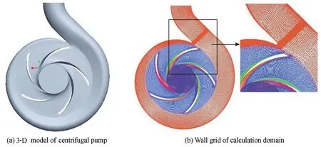
Fig. 1 3-D model of centrifugal pump and wall grid of calculation domain
3.2 Numerical method and boundary conditions
With the CV-FEM method being used in ANSYS CFX 12, the linearized momentum and mass equations were solved simultaneously with an algebraic multi-grid method based on the additive correction multi-grid strategy. The implementation of this strategy in ANSYS CFX has been found to be very robust and efficient in predicting the swirl flow in turbomachinery. The high resolution scheme was adopted in space discretization to solve the differential equation, and it had the second-order space accuracy.
Under the cavitation and non-cavitation conditions, the boundary conditions were specifically set, almost the same as one another. Generally, the total pressure at the pump inlet and mass flow rate at the pump outlet were selected. As for the wall boundary condition, a no-slip condition was enforced on the wall surface, and the automatic wall function was selected for the area near the wall. In addition, detailed analysis was performed on the measurement parameter (y+) of wall grids, and the y+ values were less than 10, which essentially met the calculation requirements. For the cavitation case, the volume fractions of vapor and water were assumed to be 0 and 1, respectively.
4 Results
For the convenience of dealing with the data from experiments and computations, the flow coefficientϕis defined as, with; the cavitation numberσas, withpinbeing the static pressure at the pump inlet; the head coefficientψas, withpoutbeing the static pressure at the pump outlet; and the total pressure coefficient, withptandptinbeing the total pressure for the pump and the total pressure at the pump inlet, respectively.
4.1 Head coefficient dropoff curves under cavitation conditions
Fig. 2 shows the computed and experimental results with two turbulence models for three values of the flow coefficient. In the experiment, the decrease ofσwas achieved bydecreasing the pressure in the cavitation tank 5 to 10 kPa each time. Fig. 2 illustrates that the simulation results of the two turbulence models are in agreement with the experimental one for each flow coefficient. In addition, the simulation results of the modifiedk-ωmodel are closer to the experimental data than the standardk-ωmodel at the design flow coefficient (φ= 0.102) and low flow coefficient (φ= 0.082). However, with the high flow coefficient (φ= 0.122), the head coefficient dropoff curves computed with two turbulence models have almost no difference.
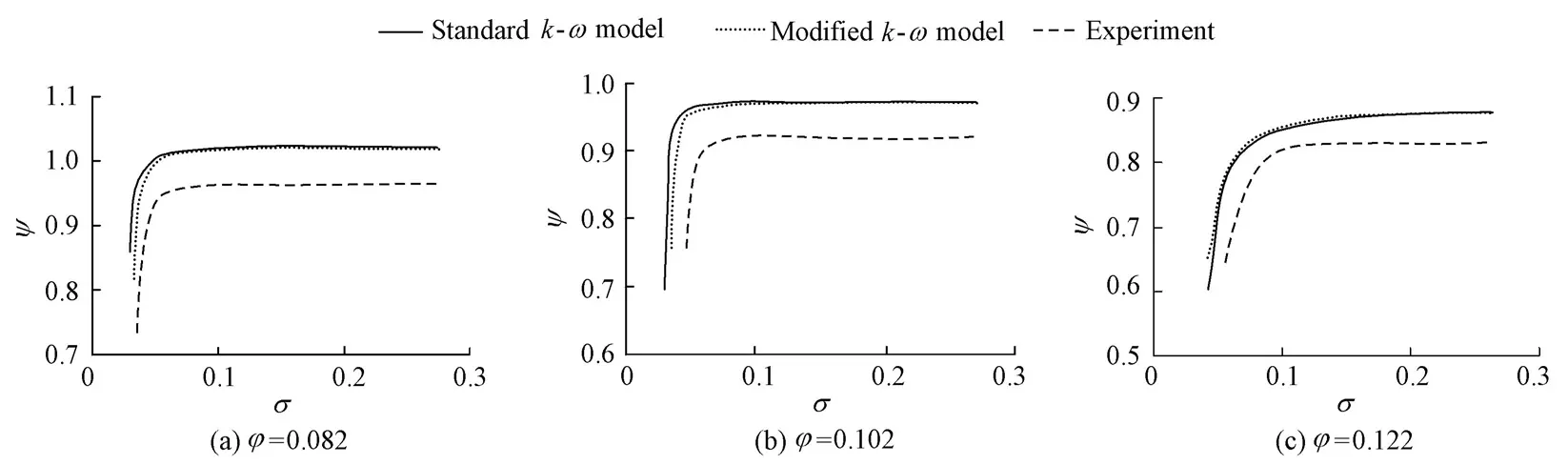
Fig. 2 Comparison of computed and experimental head coefficient dropoff curves with three values of flow coefficient
It can be seen that there is a certain deviation of the pump head coefficient between the simulated and experimental values. The difference is probably due to friction losses and imperfection of the CFD codes, as well as inaccuracies in the geometry.
The predicted and experimental critical cavitation numbers for three different values of the flow coefficient are listed in Table 1. The critical cavitation numberσcis defined as the cavitation number corresponding to the head coefficient falling off 3%.
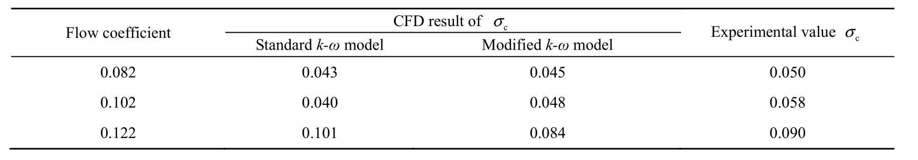
Table 1 Critical cavitation numbers obtained with different turbulence models and experiments
Based on the above analysis, it is concluded that the prediction precision of the modifiedk-ωmodel is higher than that of the standard model. Therefore, the modified model is more suitable for numerical simulation of the cavitating flow in centrifugal pumps.
4.2 Vapor volume fraction distribution
The vapor volume fraction contours on the cutting plane of the impeller with a span of 0.8 are plotted in Fig. 3, where the span is the dimensionless distance (between 0 and 1) from the hub to shroud.
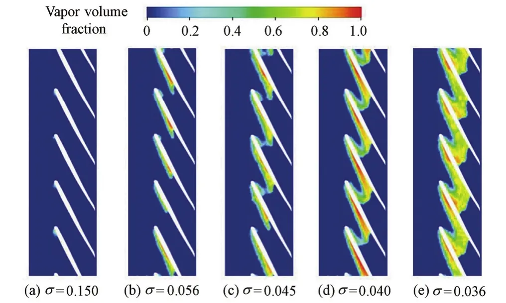
Fig. 3 Blade-to-blade view of vapor volume fraction on cutting plane with span of 0.8
Forσ= 0.150, small cavities can be clearly seen on the suction side, attaching to the blade leading edge. The developing process of cavitation is also clearly observed on the pressure side: forσ= 0.056, cavities grow significantly; forσ= 0.045, cavities on the pressure side interact with those on the trailing edge of the neighboring blade; and forσ= 0.036, the channel is completely obstructed by cavities, generating large blockage to the internal flow and directly contributing to the breakdown of pump performances.
Remarkably, the volume fraction distribution in the impeller passage shows asymmetry due to the existence of the volute, which breaks the symmetrical characteristic of the impeller passage and the coupling effects between the impeller and volute, making pressure distribution on the blade surface asymmetric.
4.3 Total pressure coefficient distribution in impeller passage
To study the energy transfer in the centrifugal pump, the impeller passage was divided into eight different regions by nine sections, from S0 near the blade leading edge to S8 near the blade trailing edge, as shown in Fig. 4. Subsequently, an analysis of the cavitating flow was performed in the eight flow regions.
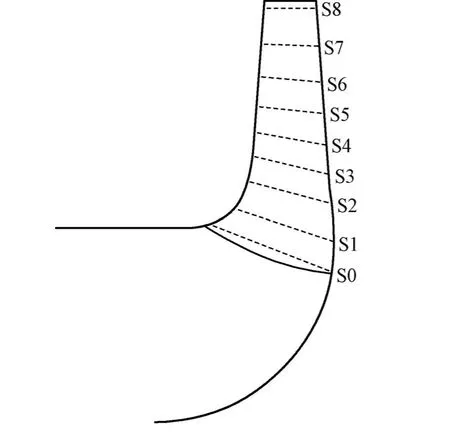
Fig. 4 Location of analyzed flow regions in impeller
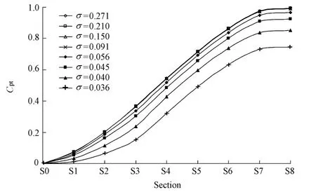
Fig. 5 Repartition of total pressure coefficient
First of all, the total pressure coefficient of each section was computed by mass flow averaging from S0 to S8. Then, the rise of the total pressure coefficient from S0 to S8 was drawn. It can be seen clearly in Fig. 5 that the decrease of the difference between the totalpressure coefficients of two adjacent sections with the decrease of the cavitation number principally takes place in the upstream sections S0 to S3, while the development of cavitation has less effect on the downstream sections S4 to S8. Although the last fourσvalues are nearly constant, with the values varying from 0.056 to 0.036, the total downstream pressure coefficient for each section continues to decrease. In addition, it can be observed that the difference of the total pressure coefficients between S3 and S4 increases in the cases ofσ= 0.045 andσ= 0.040. Nevertheless, the difference between the total pressure coefficients of two adjacent downstream sections from S4 to S8 does not increase.
5 Conclusions
This paper presents a modifiedk-ωmodel and introduces a cavitation model frequently used in hydrofoils and propellers to model the cavitating flow in a centrifugal pump.
The numerical investigation clearly demonstrates that the breakdown of pump performances is mainly due to the development of cavitation. The vapor-filled cavities attaching on blades fill up the impeller passage, resulting in the flow separating from the blades, and consequently the drop of the head coefficient.
Furthermore, it is found that with the decrease of the cavitation number, the cavity generates on the suction side of blades near the leading edge at first and then expands to the impeller outlet, and that the total pressure coefficient of each impeller section decreases, with the development of cavitation mainly affecting the upstream sections and having less effect on the downstream sections.
In a word, the simulation results indicate that the application of the modifiedk-ωmodel and the Schnerr-Sauer model can truly show the decline of the pump performance and improve the prediction accuracy.
Coutier-Delgosha, O., Fortes-Patella, R., and Reboud, J. L. 2002. Simulation of unsteady cavitation with a two-equation turbulence model including compressibility effects.Journal of Turbulence, 3(1), 58-65. [doi:10.1088/1468-5248/3/1/058]
Coutier-Delgosha, O., Reboud, J. L., and Fortes-Patella, R. 2003a. Evaluation of the turbulence model influence on the numerical simulations of unsteady cavitation.Journal of Fluids Engineering, 125(1), 38-45. [doi:10.1115/1.1524584]
Coutier-Delgosha, O., Hofmann, M., Stoffel, B., Fortes, P. R., and Reboud, J. L. 2003b. Experimental and numerical studies in a centrifugal pump with two-dimensional curved blades in cavitating condition.Journal of Fluids Engineering, 125(6), 970-978. [doi:10.1115/1.1596238]
Frikha, S., Coutier-Delgosha, O., and Astolfi, J. A. 2009. Inf l uence of the cavitation model on the simulation of cloud cavitation on 2D foil section.International Journal of Rotating Machinery, 2008(45), 1-12. [doi:10.1155/2008/146234]
Li, D. 2011. Prediction of non-cavitating and cavitating performance of a SVA Potsdam propeller.Second International Symposium on Marine Propulsors. Hamburg: Hamburg University of Technology.
Li, H. Y., Kelecy, J. K., Egelja-Maruszewski, A., and Vasquez, S. A. 2008. Advanced computational modeling of steady and unsteady cavitating flows.2008 American Society of Mechanical Engineers (ASME) International Mechanical Engineering Congress and Exposition.Boston: ASME.
Liu, H. L., Wang, Y., Yuan, S. Q., Tan, M. G., and Wang, K. 2010. Effects of blade number on characteristics of centrifugal pumps.Chinese Journal of Mechanical Engineering, 23(6), 742-747. [doi:10.3901/CJME. 2010.06.742]
Liu, L. J., Li, J., and Feng, Z. P. 2006. A numerical method for simulation of attached cavitation flows.International Journal for Numerical Methods in Fluids, 52(6), 639-658. [doi:10.1002/fld.1192]
Olsson, M. 2008.Numerical Investigation on the Cavitating Flow in a Waterjet Pump. Ph. D. Dissertation. Sweden: Chalmers University of Technology.
Pierrat, D., Gros, L., Couzinet, A., Pintrand, G., Le Fur, B., and Gyomlai, Ph. 2008. Experiment and numerical investigations of leading edge cavitation in a helico-centrifugal pump.The 12th International Symposium on Transport Phenomena and Dynamics of Rotating Machinery.
Sato, T., Nagahara, T., and Suzuki, S. 2009. Cavitation analysis on double-suction volute pump.Third International Association for the History of Religions (IAHR) International Meeting of Workshop on Cavitation and Dynamic Problems in Hydraulic Machinery and System. Brno: IAHR.
Schnerr, G. H., and Sauer, J. 2001. Physical and numerical modeling of unsteady cavitation dynamics.Fourth International Conference on Multiphase Flow. New Orleans: ICMF.
Sezal, I. H., Schmidt, S. J., Schnerr, G. H., Thalhamer, M., and Förster, M. 2006. Shock and wave dynamics of compressible liquid flows with special emphasis on unsteady load on hydrofoils and on cavitation in injection nozzles.Sixth International Symposium on Cavitation. Wageningen: Maritime Research Institute Netherlands.
Singhal, A. K., Athavale, M. M., Li, H. Y., and Jiang, Y. 2002. Mathematical basis and validation of the full cavitation model.Journal of Fluids Engineering, 124(3), 617-624. [doi:10.1115/1.1486223]
Wang, Y., Liu, H. L., Yuan, S. Q., Tan, M. G., and Wang, K. 2011. CFD simulation on cavitation characteristics in centrifugal pump.Journal of Drainage and Irrigation Machinery Engineering, 29(2),99-103. [doi:10.3969 /j. issn.1674-8530] (in Chinese)
Wilcox, D. C. 2006.Turbulence Modeling for CFD. California: DCW Industries.
Wu, J. Y., Utturkar, Y., Senocak, I., Shyy, W., and Arakere, N. 2003. Impact of turbulence and compressibility modeling on three-dimensional cavitating flow computations.33rd AIAA Fluid Dynamics Conference and Exhibit. Orlando: American Institute of Aeronautics and Astronautics .
Wu, J. Y., Wang, G. Y., and Shyy, W. 2005. Time-dependent turbulent cavitating flow computations with interfacial transport and filter-based models.International Journal for Numerical Methods in Fluids, 49(7), 739-761. [doi:10.1002/fld.1047]
Zwart, P., Gerber, A. G., and Belamri, T. 2004. A two-phase model for predicting cavitation dynamics.Fifth International Conference on Multiphase Flow. Yokohama: ICMF.
(Edited by Ye SHI)
This work was supported by the National Natural Science Foundation of China (Grants No. 51179075 and 51239005) and A Project Funded by the Priority Academic Program Development of Jiangsu Higher Education Institutions.
*Corresponding author (e-mail:liuhoulin@ujs.edu.cn)
Apr. 6, 2012; accepted Sep. 2, 2012
杂志排行

Water Science and Engineering的其它文章
- Present and future of hydrology
- Pollutant mixing and transport process via diverse transverse release positions in a multi-anabranch river with three braid bars
- Characteristics of phosphorus adsorption by sediment mineral matrices with different particle sizes
- Joint probability distribution of winds and waves from wave simulation of 20 years (1989-2008) in Bohai Bay
- Optimized operation of cascade reservoirs on Wujiang River during 2009-2010 drought in southwest China
- Towards full predictions of temperature dynamics in McNary Dam forebay using OpenFOAM