Flow and heat transfer characteristics of falling water film on horizontal circular and non-circular cylinders*
2013-06-01LUOLincong罗林聪ZHANGGuanmin张冠敏PANJihong潘继红TIANMaocheng田茂诚
LUO Lin-cong (罗林聪), ZHANG Guan-min (张冠敏), PAN Ji-hong (潘继红), TIAN Mao-cheng (田茂诚)
School of Energy and Power Engineering, Shandong University, Jinan 250061, China, E-mail: luolc1115@mail.sdu.edu.cn
Flow and heat transfer characteristics of falling water film on horizontal circular and non-circular cylinders*
LUO Lin-cong (罗林聪), ZHANG Guan-min (张冠敏), PAN Ji-hong (潘继红), TIAN Mao-cheng (田茂诚)
School of Energy and Power Engineering, Shandong University, Jinan 250061, China, E-mail: luolc1115@mail.sdu.edu.cn
(Received January 11, 2013, Revised March 8, 2013)
This paper presents a two-dimensional CFD study of the falling film evaporation of horizontal tubes with different shapes applied in the seawater desalination. The flow and heat transfer characteristics of the falling water film on one circular tube and two non-circular shaped tubes, a drop-shaped tube and an oval-shaped tube, are analyzed, respectively. The Volume Of Fluid (VOF) method is employed to investigate the influence of the mass flow rate and the feeder height on the distribution of the film thickness and the heat transfer performance. The numerical results show that the minimum value of the film thickness appears approximately at the angular positions of 125o, 160oand 170ofor the smooth circular, oval- and drop-shaped tubes, respectively. The film thickness grows with the increase of the mass flow rate and the decrease of the feeder height, while the variation pattern varies for different tubes. Moreover, compared with the circular tube, the drop- and oval-shaped tubes have a lower dimensionless temperature and a thinner thermal boundary layer, which means a better heat transfer performance. Finally, the numerical results correlate well with the experimental and predicted data in literature.
non-circular cylinder, falling film, numerical simulation, heat transfer enhancement, desalination
Introduction
The falling film evaporators are widely applied in several industrial processes (the chemical engineering, the food drying, the air-conditioning industries and the Ocean Thermal Energy Conversion (OTEC) systems, etc.) due to their high heat transfer coefficients at low mass flow rates and small temperature differences. The complex heat and mass transfer properties of the falling film evaporator have attracted many theoretical and experimental studies, including those of the flow mode classification and the flow and heat transfer characteristics of the falling film with or without evaporation[1-3].
When a liquid film flows from one horizontal tube to another below it, according to an increasing flow rate order, the liquid film flow might be in the droplet, jet or sheet mode, which plays an important role in the heat and mass transfer process. Mitrovic[4]studied the flow structure of a liquid film falling across a vertical array of horizontal tubes, and provided flow mode transition expressions with the Reynolds number as a function of the Kapitza number.
The heat transfer performance is of crucial significance in practical applications of falling film evaporators, and the heat transfer coefficient h was much studied. Wang et al.[5]developed a mathematical model in calculating the outside heat and mass transfer of the enhanced tubes and discussed the effects of the rib height and the inclined angle of the rib tube on the heat and mass transfer and found that the traverse rib tube and the spiral rib tube are more efficient than the smooth tube in the absorber. Li et al.[6,7]experimentally studied the falling film evaporation of water on six-tube arrays made of enhanced or smooth tubes at a low film Reynolds number, found that the enhanced tubes can provide a better heat transfer performance and presented correlations to predict hand the enhancement ratio. Reviews of the flow and heat transfercharacteristics for the falling film evaporation with plain smooth surfaces and enhanced surfaces were presented by Thome[8]and Ribatski and Jacobi[9]. The former focused on studies published from 1994 to 1999 while the latter, published in 2005, covered the flow pattern studies, the experimental parameters that affect the heat transfer performance on plain single tubes, enhanced surfaces and tube bundles, and the mathematical models and the empirical correlations for h. With the employment of enhanced surfaces, a higher hand a better liquid distribution can be obtained as compared with the use of plain surfaces[10,11].
In recent years, many numerical methods were developed in the study of the falling film evaporation by direct numerical simulations or by using CFD software. Ouldhadda et al.[12]investigated the effects of operational parameters on heat transfer characteristics, such as the mass flow rate, the concentration of the carboxymethlcellulose solutions, the inlet temperature and the cylinder diameter, for the falling film on a horizontal circular tube for a pseudoplastic non-Newtonian liquid. Asbik et al.[13]numerically studied the boundary layer transition between the turbulent and laminar regimes during the evaporation of the water film on the horizontal elliptical cylinder. Based on the experimental work and the numerical simulation, the effects of the Reynolds number, the hysteresis, the cylinder diameters, the positions of the cylinders and the intertube spaces on the falling film mode and the heat transfer characteristics were studied by Jafar[14]. The flow behaviors of the liquid film flow over horizontal cylinders were studied via two-dimensional numerical simulations by Sun et al.[15]. It was shown that the heat transfer coefficient enhances at the sheet mode, decreases in the jet mode and further decreases in the droplet mode. A distributed parameter model for simulating the steady-state performance of a practical horizontal tube falling-film evaporator was developed to predict the distribution of thermal parameters[16].
While many studies were focused on a circular cylinder for the liquid falling film, the falling film flow on a non-circular cylinder has not received an adequate attention. The present work performs a numerical experiment to investigate the hydrodynamics and heat transfer characteristics of the liquid falling film on non-circular enhanced tubes in the falling film evaporators for the low-temperature multieffect distillation (LT-MED), which is one of the rapidly developing technologies in the seawater desalination. A detailed numerical simulation of the flow field and the heat transfer is carried out for the water film on a drop-shaped tube and an oval-shaped tube, and their superiority over the circular tube is discussed. The effects of the tube type, the mass flow rate and the feeder height on the distribution of the film thickness around the tubes are investigated and the variations of the heat transfer coefficient across the liquid film are analyzed.
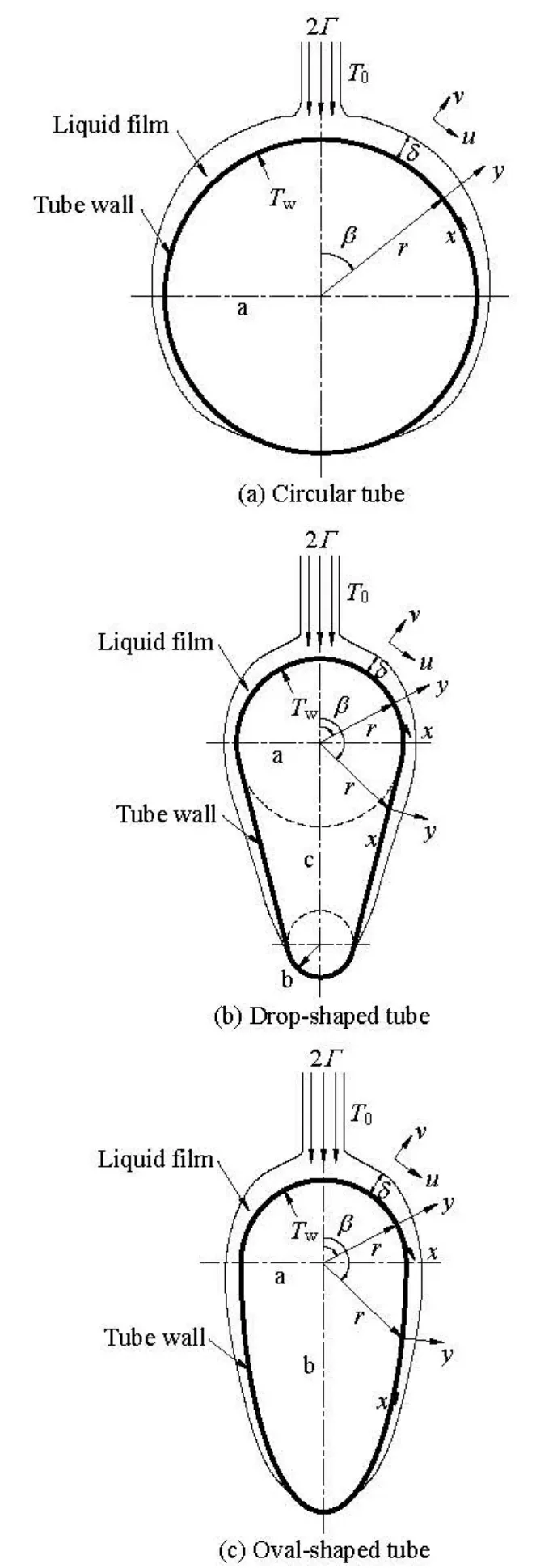
Fig.1 Physical models and coordinate systems
1. Formulation and analysis
1.1 Physical model
The present analysis considers three infinitely long heated horizontal cylinders: one circular tube of 0.019 m in diameter and two non-circular cylinders of drop-shape and oval-shape, respectively. The cross section of the drop-shaped tube is comprised of upper and lower semicircles and their external common tangents while that of oval-shaped tube is made up ofupper semicircle and lower semi ellipse. The cross sections of non-circular tubes are obtained by an optimization design, and their effective heat transfer area is identical to that of the circular tube. The liquid impinges on the top part of the tube as a continuous sheet, with a uniform inlet temperature T0and an initial mass flow rate of2Γ. The tube is exposed to the static vapor at the saturated temperature Ts. The film flows along the tube under the combined effect of the gravity, the viscous force and thesurface tensionat the liquid-vapor interface. The heat is transferred from the hot cylinder wall with a constant and uniform temperatureTw,through the liquid film to the liquidvapor interface. Figure 1 shows the physical models and the body-fitted coordinates. The coordinatexis measured from the stagnation point of the tubes and yis measured normally from the surface wall to the fluid. The velocity components inx- andy-directions areuandv, respectively.

Table 1 Structure parameters for cylinders
The parameters of the three cylinders in the simulation are listed in Table 1, of whicha is the radius of the circular tube, the radius of the upper semi-circle for both drop- and oval-shaped tubes, respectively,b represents the radius of the bottom semicircle for the drop-shaped tube and the ellipse semi-major axis,cis the distance between the centers of the two semi-circles for the drop-shaped tube,r is the distance between the surface of the tube and the centre of the upper semi-circle,βis the polar angle.
Considering the fact that thoe brine temperature for LT-MED is usually below 70C to prevent the scaling on the heat transfer surfaces, the saturated temperature Tsof the water is set as 60oC and the exterior space environment is assumed to be full of the saturated water vapor at the same temperature. The thermophysical properties of fluids are listed in Table 2.

Table 2 Thermophysical properties of fluids
The film Reynolds number of the water is defined as

whereΓis the mass flow rate per unit length on each side andµis the dynamic viscosity.
According to the work of Ouldhadda et al.[12], the flow is considered to be laminar when the film Reynolds number is between 400 and 4 000. Considering that the film Reynolds number ranges from 1 702 to 4 171 in this study, the laminar model can be adopted for the numerical investigation
In addition to these considerations, the major assumptions in this study are summarized as follows: (1) The flow and the heat transfer are two-dimensional and the flow is laminar. (2) The liquid film thickness is considered to be thin as compared with the curvature radius of the cylinder surfaces, (3) The fluids are incompressible, (4) At the liquid-vapor interface, the shear stress is negligible. (5) The thermophysical properties of the fluids are constant and the local thermodynamic equilibrium is satisfied. (6) The inlet temperature T0of the liquid is equal to the saturated temperature Ts. (7) The phase transition is negligible and only the heat transfer from the heated wall to the film surface is considered.
1.2 Mathematical model
With the above hypotheses, the equations of the continuity, the momentum and the energy for the twodimensional incompressible unsteady laminar film flow take the following forms:
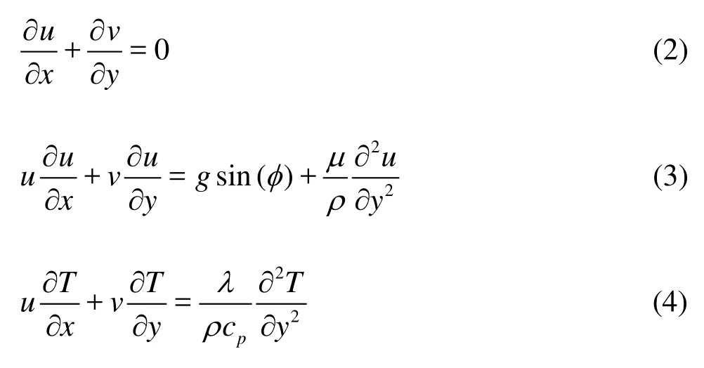
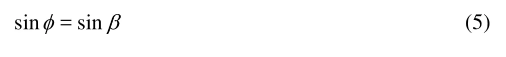
whereg,ρ,µandTare the gravity acceleration, the density, the viscosity and the temperature of the fluids, respectively,uandvare the velocity components in thex- andy -direction, respectively,cpis the specific heat,λis the thermal conductivity,φis the included angle between the gravitational vector and they-direction of the curvilinear coordinate systems, and can be obtained as follows:
For circular cylinder
For drop-shaped cylinder

Equations (2)-(4) are solved subject to the following boundary conditions:

The dimensionless temperatureθand the dimensionless normal distance from the surface (dimensionless thickness,η) are used to characterize the heat transfer performance, which are defined by

wherey is the coordinate normal to the surface,δis the film thickness.
The local Nusselt number is defined by
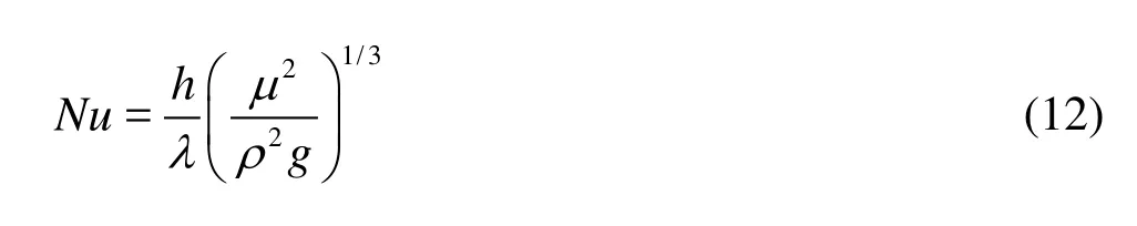
whereh represents the local heat transfer coefficient,

2. Numerical solution
2.1 Numerical methodologies
The conservation Eqs.(2)-(4), with the corresponding boundary conditions (8) and (9), are solved numerically after a coordinate transformation by a commercial CFD code, Fluent based on the finite volume method. As is shown in Fig.2, a half section is considered to obtain a faster solution under the condition of the axial symmetry of the falling film flow around the tube. A structured mesh is applied in view of the effect of the interfacial waves and the surface tension on the liquid film flow[14]. The adjacent region around the tube wall is carefully meshed using a boundary layer mesh refinement technique, making it possible to observe the water flow around the tube and to calculate the water film thickness precisely.
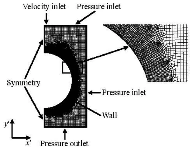
Fig.2 Numerical model with the boundary conditions
The boundary conditions for the numerical solution are set as shown in Fig.2. The left top boundary with a width,H1, of 0.001 m is set as the velocity inlet boundary, where the liquid water flows downward uniformly at different mass flow rates 0.2 kg/ms, 0.29 kg/ms, 0.39 kg/ms and 0.49 kg/ms. The remaining right top and the right vertical boundaries are set as the pressure inlet while the bottom boundary is the pressure outlet. These pressure boundaries have a gauge total pressure of –81 405 Pa and a total temperature of 333 K, which are set in the panel of settings of Fluent. The left vertical boundary is set as the symmetry plane and the semi-circle with a radius of 0.0095 m represents the heated cylinder wall with aconstant and uniform temperature Tw, 335 K. The contact angle is set as 20oin this study considering that the film shape is quite similar to the experimental results under the condition of a contact angle of 20oin the work of Lei and Li[17]. The distance between the inlet and the top of the tube is defined as the feeder height, S. For each kind of cylinder, S takes values of 0.006 m, 0.009 m, 0.012 m and 0.015 m for the simulation. Therefore, the same approach is employed in the non-circular cylinder modeling as shown in Fig.1. Table 3 summa- rizes the simulation model and the discretization con- ditions for the falling film of the three cylinders.

Table 3 Fluent two-dimensional simulation settings
In the numerical simulation process, the Cartesian coordinate system is adopted for convenience of calculations through Fluent software. The boundary conditions of the far field are expressed as follows:
(1) Velocity inlet boundary

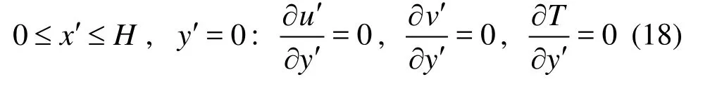
(4) Pressure outlet boundary wherex′andy′are the Cartesian coordinates of the computational domain,u′andv′are the velocity components in thex′- andy′-direction, respectively, H and H1are the whole width of the computational region and the width of velocity inlet inx′-direction, respectively,Land L1are the whole height of the computational region and the distance fromy′=0to the bottom of the tube iny′-direction.
2.2 Grid independence verification
To obtain a grid independent solution, numerical experiments with several grid arrangements are performed and the comparison of the water film thickness is shown in Fig.3 for the circular tube case with a constant mass flow rate of 0.29 kg/ms and a feeder height of 0.009 m.

Fig.3 Grid independence verification
It should be noted that the differences in the film thickness from computations using the 8 293, 10 613 and 14 422 total grid elements are always within 2.0%. A grid scheme with 10 613 total mesh elements is finally chosen for the subsequent computations under the consideration of the computation time and the accuracy of solution. In the same way the mesh independence for the drop- and oval-shaped tubes is verified. It can be concluded that the present numerical algorithm and the grid layout employed are adequate to obtain accurate results for the falling film simulations.
3. Results and discussions
3.1 Distribution of liquid film
In the simulation process, the evaporation and the condensation at the liquid-vapor interface are neglected and the wall temperature of each tube is assumedto keep a constant and uniform temperature of 62oC. The falling film liquid with a saturation temperature of 60oC remains unchanged before contacting with the tube wall, after contacting with the tube wall, the liquid temperature increases in the process of absorbing heat from the hot tube wall. Then the hot liquid transfers heat to the vapor near the liquid-vapor interface, which makes the vapor temperature increase from an initial saturation temperature of 60oC. For a fully developed laminar film flow, the heat transfer across the film can be approximated as a one-dimensional heat conduction, making the circumferential thickness of the liquid film an important factor affecting the local heat transfer coefficient.
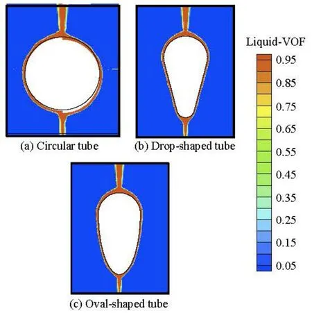
Fig.4 Contours of falling film for different tubes

Fig.5 Variations of film thickness for oval-shaped tube at different mass flow rates (S =9×10⁻³m)
The flow visualizations of the falling liquid film over the three kinds of horizontal tubes under the steady state at Γ=0.29 kg/ms are shown in Fig.4, where the water phase with the liquid volume fraction of 1 is in red and the vapor phase with the liquid volume fraction of 0 is in blue and the liquid-vapor interface is between red and blue. It is shown that the film thickness first decreases and then increases slowly along the angular position for the circular tube while the film thickness practically decreases continuously for the non-circular tubes. Besides, the film thickness on the bottom of the tube is the largest for the drop-shaped tube, the smallest for the oval-shaped tube, and the intermediate for the circular one. The reason might be that the features and the modes for the liquid falling off the tube bottom vary for different tube types.
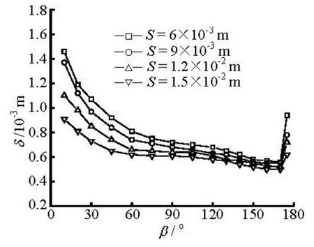
Fig.6 Variations of film thickness for drop-shaped tube at different feeder heights (Γ=0.29 kg/ms)

Fig.7 Variations of film thickness for different tubes at given mass flow rates (S =9×10⁻³m)
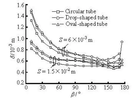
Fig.8 Variations of film thickness for different tubes at given feeder heights (Γ=0.29 kg/ms)
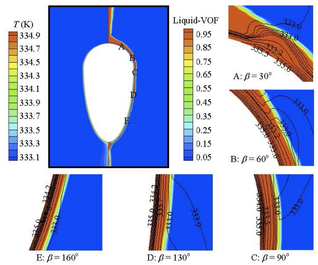
Fig.9 Temperature distribution in liquid film of oval-shaped tube
Figure 5 shows that the liquid film thickness for the oval-shaped tube increases with the mass flow rate at a feeder height of 0.009 m. The change of the film thickness is not apparent due to the stagnation zone on the top region of the tube, while with the fluid flowing by, the effect of the mass flow rate becomes more evident on the film thickness. According to Fig.5, the film thickness reaches its minimum approximately at the angular position of 160o. Figure 6 presents the distribution of the film thickness along the drop-shaped cylinder with different feeder heights. The film thickness tends to decrease with the increase of the feeder height and the phenomenon is more obvious on the upper part of the tube than on the lower part. The straightforward reason is that a greater spray height leads to a greater impingement velocity of the fluid upon the tube wall, which makes the stagnation zone on the upper semicircle more extensive and the fluid film spread thinner; while the influence of the falling liquid impingement weakens considerably on the lower semicircle of the tube, and consequently the liquid film thickness is hardly affected.
The influences of the mass flow rate and the feeder height on the behavior of the falling film are plotted against the angular position for different tubes in Fig.7 and Fig.8. It can be seen that the film thickness increases as the mass flow rate increases for each tube, and decreases with the increase of the feeder height. On the upper semicircle of the tube, the film thickness of the drop-shaped tube is close to that of the oval-shaped tube, and the film thickness at the same βdecreases in the order of the oval-shaped tube, the drop-shaped tube and the circular tube. Taking the case of the mass flow rate of 0.49 kg/ms shown in Fig.7, as an example, the average film thicknesses of the drop- and oval-shaped tubes are 14.13% and 17.39% larger than that of the circular tube, respectively while the film thickness of the oval-shaped tube is 4.17% larger than that of the drop-shaped tube. The main reason is that the curvature of the upper part of the circular tube is the smallest, and thus the change rate of the flow velocity on the surface is the smallest as compared with the non-circular tubes under the same flow discharge conditions[18]. On the lower part of the tube, the film thickness of the circular tube remains nearly constant in the angle range between 90oand 140o. However, the curvatures of the lower part for non-circular tubes are smaller than that of the circular tube, which results in a larger gravity component in the flow direction and a larger flow rate of the liquid film. Therefore the film thickness of non-circular tubes decreases dramatically as compared with the circular tube as the angle increases on the lower part of the tube.
It is also noticed that the film thickness increases rapidly on the bottom of the tubes as the mass flow rate increases due to the effect of the gravity. However, at the mass flow rate of 0.20 kg/ms, the film thickness only has a smooth change. The possible reason is that it is difficult to accumulate enough liquid to form big droplets on the bottom when the flow rate is low. Moreover, for the circular, oval- and drop-shaped tubes the film thickness comes to its minimum at approximately the angular position of 125o, 160oand 170o, respectively. As shown in Fig.8, the values of the minimum film thicknesses of the oval- and dropshaped tubes are 9.80% and 1.96% smaller than that of the circular tube at a feeder height of 0.015 m, while the minimum film thickness of the oval-shaped tube is 8.0% lower than that of the drop-shaped tube. Accordingly, there is a probability to obtain an optimal tube cross section, which would effectively improve the liquid film distribution and help to obtain a thinner liquid film.
3.2 Temperature variation of the liquid film
The distribution of the film thickness and the film temperature at a mass flow rate of 0.29 kg/ms and a feeder height of 0.009 m are shown in Fig.9. Symbols A, B, C, D and E indicate the angular positions of 30o, 60o, 90o, 130oand 160o, respectively. Comparing the isograms in these figures, it is found that the temperature gradient decreases as the positional angle increases. Meanwhile, the thermal boundary layer thickens, leading to a deterioration of the local heat transfer performance. It is also noticed that the thickness of the liquid film decreases with the increase of the positional angle for the oval-shaped tube, which is in accordance with the analysis previously mentioned.

Fig.10 Variations of dimensionless temperature at representative angular positions for circular tube (Γ=0.29 kg/ms, S =9×10⁻³m)
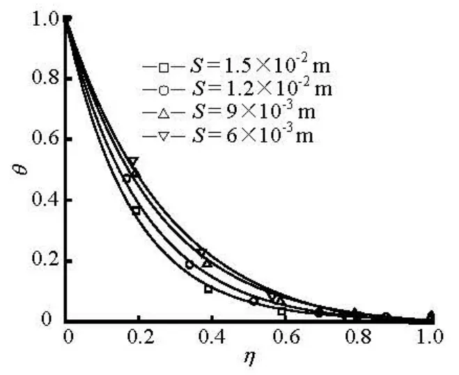
Fig.11 Variations of dimensionless temperature at different feeder heights for drop-shaped tube (β=160o,Γ= 0.29 kg/ms)
The variations of the dimensionless temperature of the liquid film with respect to the angular position, the mass flow rate and the feeder height are shown in Figs.10-14. As seen in Fig.10, the dimensionless temperature increases with the angular positionβ, indicating a decreasing local temperature gradient and a thickening thermal boundary layer, which worsens the local heat transfer performance. This is probably because of the impingement disturbance effect caused by the falling liquid upon the top part of the tube, which is helpful to the heat transfer enhancement, and weakens as the angleβrises, especially on the bottom of the tube.
Figure 11 shows the influence of the feeder height on the dimensionless temperature profiles for the drop-shaped tube, indicating that the dimensionless temperature is larger when the feeder height is smaller. This is due to the increase of the film thickness and the reduction of the flow perturbation under the condition of smaller feeder heights, which worsens the heat transfer performance.
蒋浩德随即起身告辞,看见水仙芝的妈妈雨心正在炒菜。话到嘴边,他又改口了:“老同学太盛情啦,看来我走不了!”
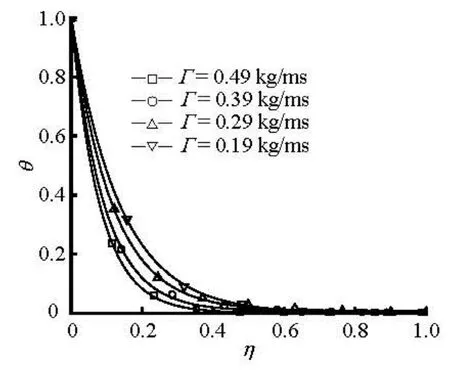
Fig.12 Variations of dimensionless temperature at different mass flow rates for oval-shaped tube (β=60o,S= 9×10⁻³m)

Fig.13 Variations of dimensionless temperature for different tubes at different angular positions (Γ=0.29 kg/ms, S =1.5×10⁻²m)

Fig.14 Variations of dimensionless temperature for different tubes at different mass flow rates (β=90o,S=9× 10⁻³m)
Figure 12 shows that with the increase of the mass flow rate, the dimensionless tempeorature decreases for the oval-shaped tube at β=60. This can be explained by the larger impacting force on the top of the horizontal tube and the greater flow disturbance due to the increase of the mass flow rate. Therefore, higher mass flow rates are beneficial for higher heat transfer coefficients.
Figures 13 and 14 show the variation of the dimensionless temperature for different tube types at fixed angular positions of 30oand 130oand at different mass flow rates of 0.20 kg/ms and 0.49 kg/ms, respectively. As can be seen from these figures, the dimensionless temperature for non-circular tubes is invariably smaller than that for the circular tube at the same angular position with an identical mass flow rate. It can be inferred that the local temperature gradient for the non-circular tubes is greater than that for the circular tube, which implies better heat transfer performance, and among the three tube types the ovaltyped tube outshines the other two in the heat transfer performance. The main cause is that on the upper part of the tubes, the thermal boundary layer thickens more rapidly on the circular tube with a larger diameter than on non-circular tubes, according to Parken et al.[19], while on the lower part of tubes, the smaller curvature of non-circular tubes leads to an increase of the pressure gradient in the flow direction and a local thinning laminar sub-layer in the liquid film[13].
In brief, compared with the circular tube, the cross sections of non-circular tubes are in a better streamlined shape, and we have a greater local temperature gradient and a thinner boundary layer, which implies a better heat transfer performance.
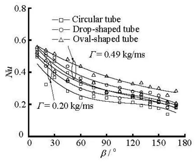
Fig.15 The variations of local heat transfer coefficient for different tubes at given mass flow rates (S =9×10⁻³m)
3.3 Local Nusselt number and model validation
The variation of the local dimensionless heat transfer coefficient,Nu , with the positional angleβ for different tubes at a fixed mass flow rate and feeder height is presented in Fig.15. The Nusselt number is relatively large as the liquid enters and then decreases downstream due to the development of the thermal boundary layer. For a fixed angular position, an increase of the local dimensionless heat transfer coefficient is observed as the mass flow rate increases. Furthermore, a higher heat transfer coefficient can be obtained for the non-circular tubes than for the circular tube on both the upper and lower parts of the tubes. Since the heat transfer coefficient is higher in the thermally developing zone, its effect is greater on tubes with smaller diameters, and hence the tubes of smaller diameter tend to have higher heat transfer coefficients[20]. The augmentation of the pressure gradient due to the tube surface curvature change generates a noticeable reduction in the laminar sub-layer and consequently extends the turbulence region[13]. Taking the condition of the mass flow rate at 0.49 kg/ms as an example, the average heat transfer coefficients of the oval- and drop-shaped tubes are increased approximately 34.03% and 12.63%, respectively, as compared with the circular tube.
These results show that the conclusions in the paper are applicable in many industrial fields, such as the seawater desalination, the food processing, and the air-conditioning, where the falling fluid has a low viscosity and the physical properties change little against the temperature in the laminar flow. They can be applied to the falling film evaporators of non-circular cylinders.
To validate the present numerical model, the numerical simulation results are compared with previous numerical and experimental results under similar conditions in literature. Both the inlet temperature and the liquid-vapor interface temperature are set as the saturation temperature Ts, while on the circular tube wall, a uniform temperature Twis assigned. In Fig.16, the modified Zazuli empirical correlation[20]for the local heat transfer coefficient is adopted, which takes account of the effects of the interfacial waviness in the range of the Reynolds number studied for the laminar falling film flow.

Fig.16 The variations of local heat transfer coefficient and comparison with experimental data

In this figure, the results of the present work are compared with the experimental results of Liu[1]and numerical predictions of Ouldhadda et al.[12]. The conditions of the latter’s research are as follows: the saturation temperature is 61.5oC, the Reynolds number is 1 500, and the tube diameter is 0.0254 m, while in the reference case of this paper, the related conditions are: the saturation temperature is 60oC, the Reynolds number is 1 702, and the tube diameter is 0.019 m, which are quite close to the above values. It can be seen in Fig.16 that the simulation results of this paper are relatively higher, which might be due to the greater Reynolds number and the smaller tube diameter. As mentioned above, a larger Reynolds number, namely, a larger mass flow rate, leads to a thinner thermal boundary layer and a better heat transfer performance. Besides, the effect of the thermally developing zone is more influential for tubes with smaller diameter, which improves the heat transfer[20]. Accordingly, the deviation between the simulation test results and Ref. [1] and [12] is reasonable and acceptable, indicating that the numerical results of this paper are reliable.
4. Conclusions
This paper studies the effect of the tube shape on the film thickness, the dimensionless temperature and the heat transfer performance of the falling water film flow by using a finite volume CFD code, Fluent. The main conclusions are as follows:
(1) The film thickness of the circular tube, the oval-shaped tube and the drop-shaped tube increases in its order on the upper part of the horizontal tubes, while the thinnest liquid film for the tubes mentioned above appears at the centre angle of 125o, 160oand 170o, respectively. It is found that the minimum film thicknesses of the oval- and drop-shaped tube are 9.8% and 2.0% less than that of the circular tube, respectively, with the mass flow rate of 0.29 kg/ms and the spray height of 0.015 m
(2) For all three tubes, there is a tendency that the film thickness rises with the increase of the mass flow rate, and it reduces with the increase of the spray height.
(3) The dimensionless temperature decreases with the increase of the mass flow rate and the feeder height, which implies a better heat transfer performance. The dimensionless temperature distribution of the drop-shaped tube is similar to that of the oval-shaped tube, and the dimensionless temperatures of both noncircular tubes are lower than that of the circular tube, indicating a thinner thermal boundary layer.
(4) The liquid film heat transfer performance of the non-circular tubes is better than the circular tube, and the oval-shaped tube is better than the dropshaped one. The average heat transfer coefficients of the oval- and drop-shaped tubes are approximately 34.03% and 12.63% higher than that of the circular tube, respectively, with a mass flow rate of 0.49 kg/ms and the spray height of 0.009 m. Finally, it is clear that the optimization of the cross section of horizontal tubes will be helpful to the film distribution improvement and the heat transfer enhancement of the falling film flow.
[1] LIU P. J. P. The evaporating falling film on horizontal tubes[D]. Ph. D. Thesis, Madison, USA: University of Wisconsin, 1975.
[2] LUO Lin-cong, ZHANG Guan-min and TIAN Maocheng et al. Numerical simulation of liquid film flow on horizontal circular and shaped cylinders for falling film evaporation[J]. Journal of Engineering Thermophy- sics, 2013, 34(4): 1-5(in Chinese).
[3] HOU H., BI Q. and MA H. et al. Distribution characteristics of falling film thickness around a horizontal tube[J]. Desalination, 2012, 285: 393-398.
[4] MITROVIC J. Flow structures of a liquid film falling on horizontal tubes[J]. Chemical Engineering and Technology, 2005, 28(6): 684-694.
[5] WANG Mei-xia, LIU Cun-fang and WANG Xin-guang et al. Study on the falling film absorption outside smooth and enhanced tubes[J]. Journal of Hydrodyna- mics, Ser. B, 2006, 18(4): 405-410.
[6] LI W., WU X. Y. and LUO Z. et al. Falling water film evaporation on newly-designed enhanced tube bundles[J]. International Journal of Heat and Mass Transfer, 2011, 54(13-14): 2990-2997.
[7] LI W., WU X. Y. and LUO Z. et al. Heat transfer characteristics of falling film evaporation on horizontal tube arrays[J]. International Journal of Heat and Mass Transfer, 2011, 54(9-10): 1986-1993.
[8] THOME J. R. Falling film evaporation: State-of-the-art review of recent work[J]. Journal of Enhanced Heat Transfer, 1999, 6(2-4): 263-277.
[9] RIBATSK G., JACOBI A. M. Falling-film evaporation on horizontal tubes–A critical review[J]. International Journal of Refrigeration, 2005, 28(5): 635-653.
[10] ROQUES J. F., DUPONT V. and THOME J. R. Falling film transitions on plain and enhanced tubes[J]. Journal of Heat Transfer, 2002, 124(3): 491-499.
[11] CHIEN L. H., TSAI Y. L. An experimental study of pool boiling and falling film vaporization on horizontal tubes in R-245fa[J]. Applied Thermal Engineering, 2011, 31(17-18): 4044-4054.
[12] OULDHADDA D., IDRISSI A. I. and ASBIK M. Heat transfer in non-Newtonian falling liquid film on a horizontal circular cylinder[J]. Heat and Mass Transfer, 2002, 38(7): 713-721.
[13] ASBIK M., ANSARI O. and ZEGHMATI B. Numerical study of boundary layer transition in flowing film evaporation on horizontal elliptical cylinder[J]. Heat and Mass Transfer, 2005, 41(5): 399-410.
[14] JAFAR F. A., Flow fields and heat transfer of liquid falling film on horizontal cylinders[D]. Ph. D. Thesis, Victoria, Canada: University of Victoria, 2011.
[15] SUN F., XU S. and GAO Y. Numerical simulation of liquid falling film on horizontal circular tubes[J]. Frontiers of Chemical Science and Engineering, 2012,6(3): 322-328.
[16] HOU H., BI Q. C. and ZHANG X. L. Numerical simulation and performance analysis of horizontal-tube falling-film evaporators in seawater desalination[J]. International Communications in Heat and Mass Transfer, 2012, 39(1): 46-51.
[17] LEI X. L., LI H. X. Numerical simulation of the behavior of falling films on horizontal plain tubes[C]. AIP Conference Proceedings, the Sixth International Symposium on Multiphase Flow, Heat Mass Transfer and Energy Conversion. Xi’an, China, 2010, 998-1003.
[18] QIU Qing-gang, CHEN Jin-bo. Numerical simulation of film formation on horizontal-tube falling film evaporators[J]. Journal of Chinese Society of Power Enginee- ring, 2011, 31(5): 357-361, 374(in Chinese).
[19] PARKEN W. H., FLETCHER L. S. and HAN J. C. et al. Heat transfer through falling film evaporation and boiling on horizontal tubes[J]. Journal of Heat Transfer, 1990, 112(3): 744-750
[20] CHEN I. Y. Heat transfer analysis of a falling-film horizontal tube evaporator[D]. Ph. D. Thesis, Madison, USA: The University of Wisconsin, 1984.
10.1016/S1001-6058(11)60379-0
* Project support by the Shandong Province Key Scientific and Technological Project (Grant No. 2008GG10007009), the Science and Technology Development Planning of Shandong Province (Grant No. 2012GGX10421).
Biography: LUO Lin-cong (1987-), Male, Ph. D. Candidate
TIAN Mao-cheng, E-mail: tianmc65@sdu.edu.cn
杂志排行

水动力学研究与进展 B辑的其它文章
- Simulation of water entry of an elastic wedge using the FDS scheme and HCIB method*
- Numerical simulation of mechanical breakup of river ice-cover*
- The characteristics of secondary flows in compound channels with vegetated floodplains*
- Analysis and numerical study of a hybrid BGM-3DVAR data assimilation scheme using satellite radiance data for heavy rain forecasts*
- Application of signal processing techniques to the detection of tip vortex cavitation noise in marine propeller*
- Numerical simulation of scouring funnel in front of bottom orifice*