Experimental Investigation on the Ballistic Resistace of Metal Plates Subjected to Impact of Rigid Projectiles
2012-07-25ZHANGWei张伟DENGYunfei邓云飞CAOZongsheng曹宗胜
ZHANG Wei(张伟),DENG Yun-fei(邓云飞),CAO Zong-sheng(曹宗胜)
(Hypervelocity Impact Research Center,Harbin Institute of Technology,Harbin 150080,Heilongjiang,China)
Introduction
The impact of target and projectile is always an important problem in civil and military engineering protection and weapon design.The investigations on the target's deformation and penetration are significant for the ballistic protection of light structure.Currently,the multi-layered structures are widely used instead of the monolithic structure.Some investigations have been carried out to reveal the effect of configuration on the ballistic behavior of targets.The ballistic limit velocity is a main index representing the ballistic resistance of target and closely relates to the failure mode,while the failure mode depends on the target's configuration,geometry,material performance,support conditions and the projectile's nose shape.
Most of penetration investigations for metal targets concentrate on the monolithic targets.The projectiles are regarded as rigid bodies in the impact process.However,a few reports consider the ballistic performances of the multi-layered targets[1-8],but the effect of material strength on the ballistic resistance of target is less involved.Therefore,it is not clear enough.Thus,it is vital important to investigate the ballistic resistance for the monolithic and layered targets.
In this paper,the influences of the number of layers and the yield strength on the ballistic resistance of monolithic and multi-layered targets are studied experimentally.The influences of the target structure and material performance on the dominant failure models are analyzed also.
1 Experiment System and Method
1.1 Experiment Setup
The impact tests were conducted on a two-stage gas gun,as shown in Fig.1,at Hypervelocity Impact Research Center,Harbin Institute of Technology.A high speed camera typed Photron FASTCAM SA5 was used to record the target penetration process of projectile and the projectile motion.From the digital images,the travel distance,impact angle,impact velocity and acceleration of the projectile during penetration were obtained.The frame rate is selected as 50 000 fps,and the resolution is 512×128 pixels.A photocell detector system having two identical light-barriers is used to measure the projectile's velocity and correct the aberra-tion in the high speed camera system.The velocities calculated from the high-speed images are in better agreement with those obtained by using the photocell system.

Fig.1 Sketch of two-stage gas gun experiment system
The velocity calculation formula can be expressed as

wherevis the impact velocity of projectile,L1is the actual length of calibration pole,L2is the length of calibration pole presented on the coordinate paper,Nis the frame rate,P1is the serial number of initial frame,P2is the serial number of ending frame,ΔMis the number of grids when projectile flies fromP1toP2.
1.2 Projectiles and Targets
The projectiles are made of alloy steel 38CrSi.After machining,they are oil hardened to a maximum Rockwell C value of 58 in order to prevent from the plastic deformation during impact.They have constant nominal average hardness of HRC 55 and HRC 19,diameter of 12.7 mm,mass of 34.5 g and CRH,i.e.ratio of nose's curvature radius to body's diameter,of 3 in all tests.The geometry of projectile can be found in Fig.2(a).
The high strength target plates are made of 45#mild carbon steel,whose yield stress is about 780 MPa after heat treatment.While the low strength target plates are made of A3 low carbon steel,whose yield strength is about 230 MPa.The square targets of 230 mm in size are fixed to a thick armor plate in a target frame by using of 8 bolts equal spaced on a circle of 170 mm in diameter,as shown in Fig.2(b).It should be noticed that the high strength targets are compared to low strength targets to investigate the effect of material characteristic on the ballistic resistance.
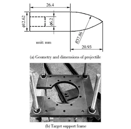
Fig.2 Geometry and dimensions of ogival-nosed projectile and target support frame
The single-layer plate is 6 mm in thick and the thicknesses of layers in the multi-layered targets are 2 mm and 3 mm,respectively.To investigate the effect of the layering,three configurations are considered.In this paper,the target code T3T3 indicates a doublelayer target whose layer thicknesses are all 3 mm,T2T2T2 is a target with three layers of all 2 mm in thickness,and T6 denotes a monolithic target with thickness of 6 mm.
2 Experiment Results
For various target combinations,there are a series of impact cases in this research.The ballistic resistance of targets is evaluated by comparing their ballistic limit velocities.For each case,the projectile's initial impact velocities vary in a wide range and the ballistic limit velocity is found when the residual velocity becomes zero.Based on the results of impact test,the curves representing the relation between residual velocity and initial velocity of the projectiles can be constructed,as shown in Fig.3 and 4.The solid lines are drawn to obtain the ballistic limit velocity by using an analytical model proposed by Recht and Ipson originally[9].It can be expressed as

whereviis the initial impact velocity,vris the residual velocity,vbis the ballistic limit velocity,aandpare undetermined constants,a=mp/(mp+mpl),mpandmplare the mass of projectile and mass of plug.Bothaandpcan be obtained by using the least square method from the experiment results.The values ofa,pandvbare given in Tab.1.

Tab.1 Ballistic limits and model parameters of targets
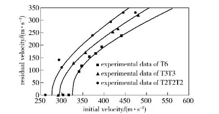
Fig.3 Residual velocities vs.initial velocities for high strength targets
It reveals that the number of layers and the yield strength of targets affect the ballistic resistance significantly.For high strength targets,the ballistic limit velocities decrease with the increase of the number of layers.For example,the ballistic limit velocity is 325 m/s for T6,294.6 m/s for T3T3,and 276.5 m/s for T2T2T2.The ballistic limit velocity of T6 is 10.3%and 17.5%larger than those of T3T3 and T2T2T2 respectively.Therefore,it can be concluded that the ballistic limit velocity is decreased when using multi-layered targets.
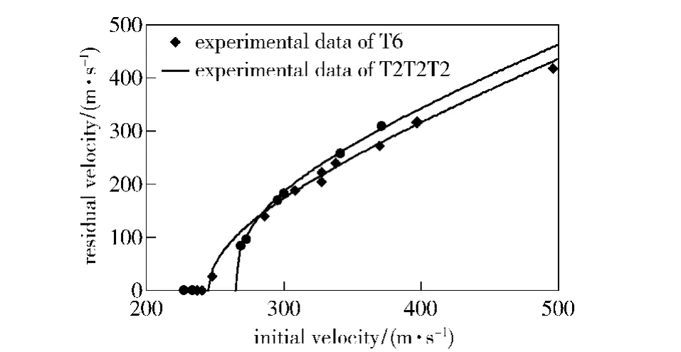
Fig.4 Residual velocities vs.initial velocities for low strength targets
However,for the low strength targets,the ballistic limit velocities of monolithic targets are lower than those of multi-layered targets.It is 245 m/s for T6 and 265 m/s for T2T2T2.The ballistic limit velocity of T2T2T2 is 8.2%larger than that of T6.The above analyses show that the layering effect of the high strength target is significantly bigger than that of the low strength target.Furthermore,the high strength targets are much stronger than the low strength targets,especially for the monolithic target.For example,the ballistic limit velocity of high strength steel T6 is 32.7%larger than that of low strength steel T6.While for T2T2T2,the high strength target is only 4.3%better than the low strength target.
3 Failure Mechanisms
The differences in the target configurations relate to the deformation mechanism and failure mode.The interaction of the perforation process with overall structural deformation is an important aspect to understand the target perforation problem.
Some typical high-speed camera images in the impact tests are given in Fig.5.From these pictures,some immediate conclusions can be drawn.The projectile keeps rigid during the process of perforation.The projectile is embedded in the target before bulge of the rear side appears.The bulge is highly localized,showing the projectile penetrate the target mainly by bending,pushing the material.After severe localized bul-ging,some petals are formed on rear side of the indentation.It should be noted that,in the tests,the projectiles rotate during perforation because of an unsymmetrical fracture process,even though the pitch angles are small,no significant angle deviation of the projectiles after perforation are found.
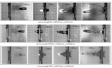
Fig.5 Typical penetration of projectile to different targets
The pictures of high strength targets perforated by projectile are given in Fig.6.The steel plate order numbers No.1,2 and 3 represent the location of plates in multi-layered targets.For the monolithic targets,the dominant failure models of plates are bulging and petaling,which involve bending and stretch tearing,as demonstrated in Fig.6(a).For the multi-layered targets,the failure modes of plates depend on their location in the target.Generally,the deformation of plates is dominated by localized bulging and petaling with small global response.The petals of the first layer are smaller but more than the second layer which is in turn than the next layer.The third layer deforms more than the second layer in turn than the next layer,the thinning of material on the bulge is found except the last layer which due to the compression between the projectile and the next layer,and also that the global deformation increases with increasing the number of layers.For T3T3,the petal in the first layer are smaller than that in the second layer,as shown in Fig.6(b).Similarly,in T2T2T2,the third layer deforms more than the second layer,and the global deformation increases with the increase of the order number of layers,as shown in Fig.6(c).From above analyses,it can be seen that the dominant failure modes do not change in T2T2T2,T3T3 and T6.
For low strength targets,the dominant failure mode of T6 is petaling caused by stretch tearing and bending,as shown in Fig.7(a).For T2T2T2,the failure mechanism depends on the plate's location,as shown in Fig.7(b).A small bulge is formed at the opposite side in the first layer,with tiny cracks on the tip of bulge,but in the case of the second layer there are a series of small cracks on a moderate bulge.Furthermore,there are a large number of moderate cracks on a big bulge in the third layer.In other words,the closer the order of layer is to rear,the larger the cracks are and the smaller the number of petals is for in-contact layered targets.From above analyses,it can be seen that the dominant failure mode changes from petaling to bulging when using T2T2T2 instead of T6.In general,the dominant failure model of T2T2T2 is bulging that the result is intense strain around the projectiles nose.
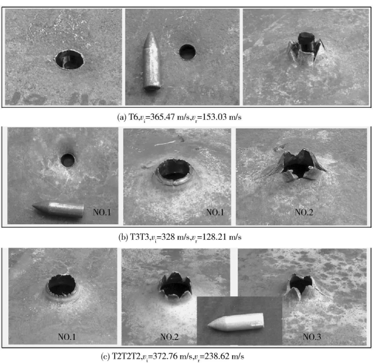
Fig.6 Deformed high strength targets

Fig.7 Deformed low strength targets
Figure 8 demonstrates deformation profiles of T2T2T2 and T6 when the impact velocities are almost equal.It indicates that the global deformation of T2T2T2 is bigger than that of T6,which may be the main reason why the ballistic limit velocity of T2T2T2 is larger than that of T6,for low strength targets.Furthermore,the deformation of the third layer is greater than that of the second layer and in turn than the first layer due to the interaction between layers.
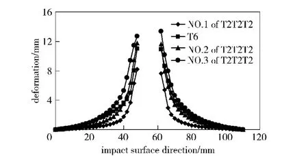
Fig.8 Deformation profiles of different low strength targets
The contrary finding of layering effect is an inter-esting phenomenon due to the different transitions of the dominant failure models and energy dissipation manners between monolithic targets and layered targets,which is in relation to the strength of targets.If there isn't transition in dominant failure models,the ballistic limit velocities are decreased when using multi-layered targets instead of monolithic targets.Otherwise,there is transition in dominant failure models,the ballistic limit velocities are increased when using multi-layered targets instead of monolithic targets.
4 Conclusions
For the monolithic and multi-layered steel targets impacted by ogival-nosed projectiles,the influences of the number of layers and the yield strength of targets on the ballistic resisitance are investigated experimentally.The results reveal that,for the high strength target,the monolithic targets are more effective than multi-layered targets,and the ballistic limit velocity increases with the decrease of the number of layers.However,for low strength target,the monolithic targets are less effective than the multi-layered targets.Furthermore,the layering effect of the high strength targets is significantly bigger than that of the low strength targets.The high strength targets are much stronger than the low strength targets,especially for monolithic targets.Finally,the number of layers and the yield strength of targets relate to the target failure mode.
[1]Flores-Johnson E A,Saleh M,Edwards L.Ballistic performance of multi-layered metallic plates impacted by a 7.62 mm APM2 projectile[J].International Journal of Impact Engineering 2011,38(12):1022 -1032.
[2]Dey S,Bovik T,Teng X,et al.Protection performance of double-layered metal shields against projectile impact[J].Journal of Mechanics of Materials and Structures,2007,2(7):1309-1330.
[3]Gupta N K,Iqbal M A,Sekhon G S.Effect of projectile nose shape,impact velocity and target thickness on the deformation behavior of layered plates[J].International Journal of Impact Engineering,2008,35:37 -60.
[4]Radin J,Goldsmith W.Normal projectile penetration and perforation of layered targets[J].International Journal of Impact Engineering,1988,7(2):229 -259.
[5]Dey S,Børvik T,Teng X,et al.On the ballistic resistance of double-layered steel plates:an experimental and numerical investigation [J].International Journal of Solids and Structures,2007,44:6701 -6723.
[6]Almohandes A A,Abdel-Kader M S,Eleiche A M.Experimental investigation of the ballistic of steel-fiberglass reinforced polyester laminated plates[J].Composite Part B:Eng 1996,27:447-58.
[7]Alavi Nia A,Hoseini G R.Experimental study of perforation of multi-layered targets by hemispherical-nosed projectiles[J].Material and Design,2011,32(2):1057 -1065.
[8]Borvik T,Langseth T,Hopperstad O S,et al.Ballistic penetration of steel plates[J].International Journal of Impact Engineering,1999,22:855 -886.
[9]Recht R F,Ipson T W.Ballistic perforation dynamics[J].Int J Appl Mech(Trans ASME),1963,30:384 -390.
猜你喜欢
杂志排行
Defence Technology的其它文章
- Velocity Correction and Measurement Uncertainty Analysis of Light Screen Velocity Measuring Method
- Environment Adaptability Evaluation for Buffering Airbag of Heavy Equipment During Airdrop Landing
- Research on Hybrid Power System with Dual Stator-winding and Its Decoupled Control Strategy
- Computational and Experimental Investigation on Aerodynamic Characteristics of Terminally Sensitive Projectile with S-C Shaped Fins
- Research on Top-layer Planning and Overall Design Project Decision of Weapon System Based on Analytic Hierarchy Process
- Research on Matching Relationship Between Number of Initiation Points and Charge Diameter
