Three Dimensional Numerical Simulation of Convection-Condensation of Vapor with High Concentration Air in Tube with Inserts*
2012-03-22CUIYongzhang崔永章TIANMaocheng田茂诚ZHANGLinhua张林华LIGuangpeng李广鹏andZHUJianbin朱建宾KeyLaboratoryofBuildingEnergyConservationTechniqueofShandongProvinceSchoolofThermalEngineeringShandongJianzhuUniversityJinan500China
CUI Yongzhang (崔永章)**,TIAN Maocheng (田茂诚), ZHANG Linhua (张林华)LI Guangpeng (李广鹏) and ZHU Jianbin (朱建宾) Key Laboratory of Building Energy Conservation Technique of Shandong Province, School of Thermal Engineering, Shandong Jianzhu University, Jinan 500 China
2 School of Energy & Power Engineering, Shandong University, Jinan 250061, China
1 INTRODUCTION
Vapor condensation with high concentration air plays an important role in the heat transfer processes[1-5], such as condensation of wet flue gas and sea water desalting with saturated moist air. It is known that air markedly reduces the condensation rate, since the air moves to the surface and accumulates there as an air-rich layer. The vapor must diffuse through the air layer and condense at the wall surface at dew point temperature, releasing both sensible and latent heats.Thus the process is a combined heat and mass transfer problem governed by mass, momentum and energy balance equations for the mixture and diffusion equation for vapor species.
As condensation acts as a sink of mass and energy,it influences physical phenomena over the entire flow domain. Three approaches are usually used to model vapor condensation with or without air: (1) models based on experimental correlations [6-8], (2) mechanistic models based on the heat and mass transfer analogy[8-11], and (3) other mechanistic models aiming to solve the governing equations in the diffusion boundary and film [12-18].
Models based on experimental correlations [6, 7]are applied to the cells adjacent to the condensation surface, with some physical variables pertaining to the bulk flow. One of the problems is to select appreciate values of the bulk flow parameters and cell width. Ivo et al. [7] examined the influence of cell width adjacent to condensation surface.
Model of heat and mass transfer analogy avoids the governing equation in boundary layer. Martin et al. [8]compared four film condensation models, and showed that models based on correlation works badly under their experimental conditions, while mechanism models based on the diffusion layer theory work well under numerous conditions, but the algorithm is very complicated. Volchkov et al. [9] concluded that the Reynolds analogy is valid under flow core xv<0.2. At higher vapor concentration the analogy is violated and the assumption of Le=1 can no longer be used. Shripad et al. [10] used an average condensation velocity to describe interfacial velocity. Krzysztof et al. [11]used diffusion layer approximation to simplify control conservation equations, and employed the low Reynolds turbulent model to resolve the near-interface region and to allow for detailed modeling the interfacial mass, momentum and energy transfer.
Two-phase numerical simulation models [12-18]employed fully coupled boundary layer equations of film and mixture. Automatic adaption was used by Groff et al. [12] to change the film thickness. Chen and Lin [13] proposed a two-phase model considering inertia, pressure gradient and turbulent influences. Riad and Salim [14] developed a condensation rate procedure applying the Fick’s law. Rao et al. [15] simulated the effect of relative humidity, Re and pressure on the gas-liquid interface temperature.
To enhance condensation heat transfer, a tube with edgefold-twisted-tape (ETT) inserts was used and studied experimentally [19, 20]. This study presents three dimensional numerical models for convection condensation thermal-hydraulics of vapor with high concentration of air under transition flow, especially condensation model of vapor condensation on the wall. The effects of parameters are studied with numerical simulation.
2 MATHEMATICAL MODELING
2.1 Physical model
Steady condensation of mixture of vapor and air in a tube with ETT inserts is illustrated schematically in Fig. 1. As superheated mixture flows through the tube, the vapor condenses and forms a thin condensate layer of thicknessδ(x) on tube surface. For small condensation flux and high swirl flow, the thickness of condensation layer is assumed to be as diameter reduction. Other assumptions are made to simplify the problem: (1) the air and water vapor forms ideal binary mixture, and physical properties are function of composition and temperature;(2) the liquid-mixture interface is under saturation conditions; (3) tube temperature is constant, inserts surface is adiabatic so that condensation does not occur; (4) the pressure is assumed to be constant in the across-section of the channel but varies inzdirection due to friction and momentum losses;(5) turbulent momentum losses in vapor condensation is negligible.
2.2 Governing equations and boundary conditions
For transient turbulent flow, the equations for continuity, momentum, energy, and species equation in the fluid can be expressed as follows:Mass equation:
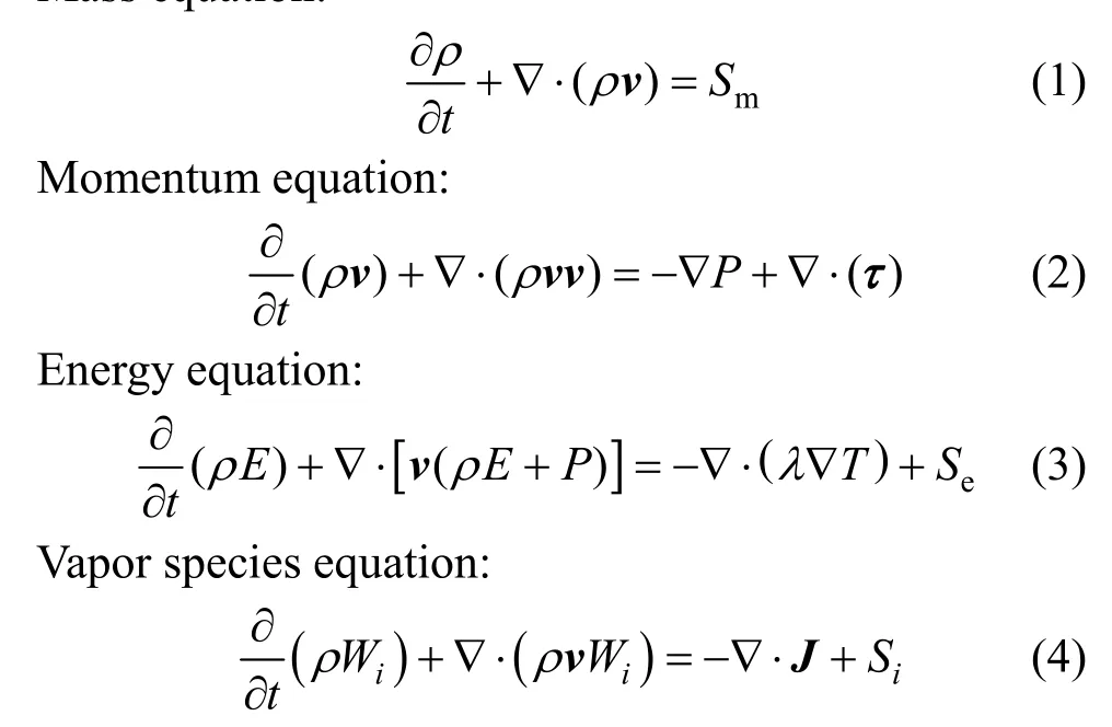

Sis defined as the source term of mass, energy and vapor species for vapor condensates on condensing wall, so condensation model is introduced into the governing equation with user defined function (UDF).
For accounting for low Reynolds number, mildly swirling flow and the flow near the wall, Realizablek-εmodel and enhanced wall treatment are adopted[21]. The air condition at the inlet is the inlet boundary condition for mass flow rate, while that at the outlet is pressure outlet boundary condition. Tube wall temperature is constant and inserts surface is insulated.The near-wall mesh is created fine enough to resolve down to the laminar sub-layer (y+≈1). The first layer cells are started at 0.1mm from the wall, which are meshed with hexahedron or wedge cells, while the cells in other regions are meshed with tetrahedron cells [19].The grid-dependence of the numerical solution has been checked carefully to ensure the accuracy and validity of the numerical results.
2.3 Condensation model
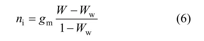
When vapor condensation occurs, there is a net flow of mixture towards the interface, resulting in a convective flow to the interface. According to the mass balance of vapor at the interface between mixture and condensation film, the condensation flux equals to the vapor transported with mixture motion and diffusion transport (Fig. 2). For the condensation flux at the wall isni, which is the bulk flow of mixture to the interface, the flux of vapor transported with the bulk flow isniWw. The flux of vapor transported with diffusive isgm(W-Ww). Then, the vapor mass fluxes at the condensing interface can be calculated by
If the layer of cells near the wall is sufficiently thin, the mass transfer coefficient of vapor species reduces to that in a laminar flow,
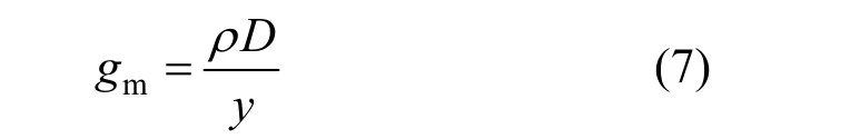
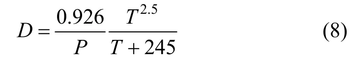
where the diffusion coefficientDof air and vapor
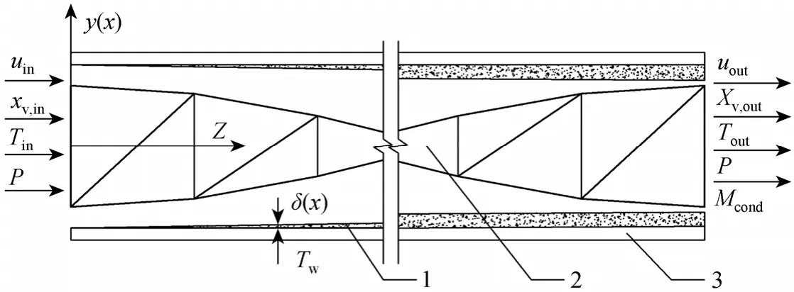
Figure 1 Convection-condensation heat transfer in a tube with edgefold-twisted-tape inserts 1—condensation film; 2—tape insert; 3—tube wall
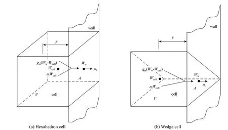
Figure 2 Cells near the condensing wall
mixture can be calculated by
The mass fraction of vapor at the interface is calculated from the vapor pressure at the interface.The Antoine equation is used to describe the vapor pressure as a function of the interfacial temperature.

For hexahedron cells and wedge cells (Fig. 2)near the condensing wall,Wcan be replaced byWcell,so Eq. (6) is rewritten as
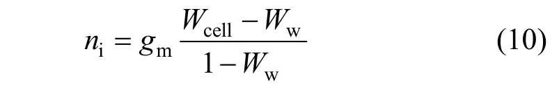
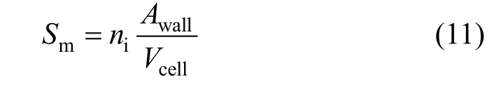
Thus the mass source of mixture with vapor condensation can be calculated by
According to the mass source, the energy source for vapor condensation is

The procedure for UDF of mass and energy sources is outlined as follows: (1) Determine the condensation surface in all cells, (2) If the temperature at cell center is higher than that of condensation wall,homogeneous condensation occurs, (3) Calculate vapor pressure, if vapor fraction at cell center is higher than that at wall, evaporation occurs, (4) Calculate the distance between the wall and cell center, mass diffusion and transfer coefficient, cell volume and condensation surface area, (5) Calculate mass source and solve differential equation, (6) Calculate latent heat of vapor and energy source, and solve differential equation.
3 RESULTS AND DISCUSSION
For evaluating the condensation model, a 360 mm long tube is used for simulation and experimental test [20]. The edgefold length is 20 mm, twist angle is 15 degree, tape width is 10 mm, and inner diameter is 12 mm. To simulate thermal hydrodynamic performance, the tube is divided into six sections with equal length. Tubes with inner diameter of 11 mm and 13 mm are selected to compare the effect of gap between tube wall and tape edge.
3.1 Condensation model validation
Condensation mass flux predicted by the condensation model, heat and mass analogy model and experiment are illustrated in Fig. 3. Condensation mass fluxes from the condensation model are 5.5%-10.7%lower than experimental results, because of the effects of coarse condensation layer and water accumulation at inserts and wall. The condensation mass flux from the heat and mass transfer analogy is 43%-62% higher than experimental results, due to the variation of mixture composition and velocity along the tube. The calculatedPrandScof mixture along the tube length are illustrated in Fig. 4, and the vapor fraction is showed in Fig. 5.
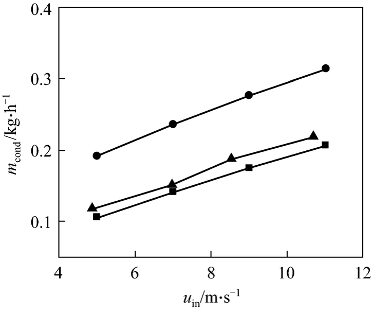
Figure 3 Comparison of condensation mass flux■ condensation model; ● heat and mass analogy; ▲ experiment
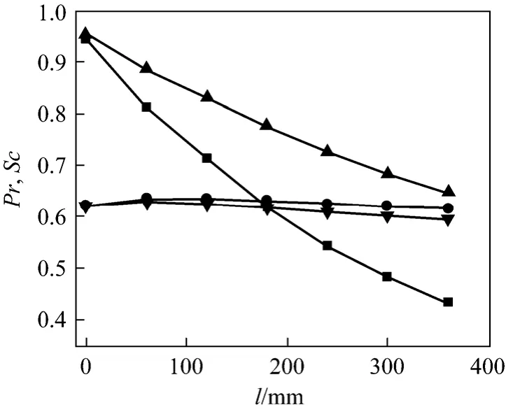
Figure 4 Pr and Sc along tube lengthPr: ■ condensation model; ● heat and mass analogy Sc: ▲ condensation model; ▼ heat and mass analogy

Figure 5 Vapor volume fractions along tube length
Pressure drops from the condensation model,heat and mass analogy and experiment are illustrated in Fig. 6. The pressure drop from condensation model is 30-41 Pa lower than experimental results, since the water layer accumulated at the surface increases turbulent loss in the experiment. The pressure drop from heat and mass transfer analogy is higher than experimental results, due to the decrease of flux mass along the tube length.
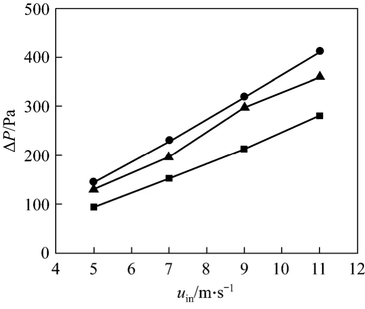
Figure 6 Comparison of pressure drop■ condensation model; ● heat and mass analogy; ▲ experiment
3.2 Condensation layer thickness
As assumed in physical model, the condensation layer is in equivalent thickness and as a diameter reduction. The experimental condensate layer profile is shown in Fig. 7 (a). According to the sectional condensation mass flux and condensate velocity along the tube length, the thickness of condensate layer can be simply calculated. From the experimental measurement, water velocity changed from 0.005 m·s-1to 0.02 m·s-1, so the average valve is assumed as 0.01 m·s-1.Under conditions ofuin=3-11 m·s-1,Tw=303 K, andTin=373 K,xv,in=0.15, the thickness of water layer from simulation is shown in Fig. 8. The thickness is between 0.02 mm and 0.16 mm. With the assumption that the condensation water drips to the tube base such as in Fig. 7 (b), the thickness is from 0.1 mm to 0.6 mm.

Figure 7 Condensate profile in tube

Figure 8 Condensate thicknesses at different vapor mass fraction■ 0.15%; ● 0.18%; ▲ 0.21%; ▼ 0.24%; ◆ 0.27%
3.3 Gap width between tape and tube
Figure 9 shows the effect of the gap width between tap and tube on heat transfer performance under simulation conditions:uin=3-11 m·s-1,Tw=303 K,andTin=373 K,xv,in=0.15. Asbincreases,qconvandqtotincreases initially and then decreases, whileqcondincreases sharply and then decrease slightly, due to the increase of velocity passing through the gap and the decrease of main velocity asbincreases. Fig. 10 shows thatqcond/qtotincreases asbincreases, sinceqconvdecreases whilesqcondchanges little. From condensation and total heat transfer, gap width of 1 mm is an optimal gap width.
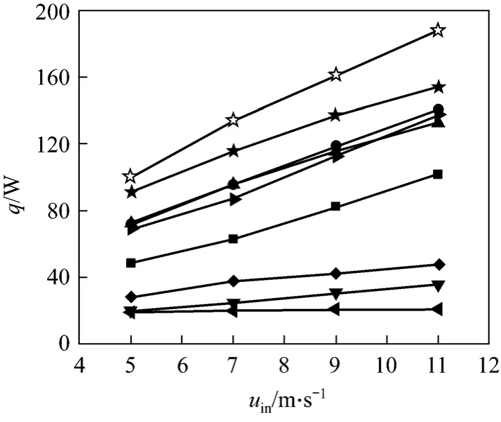
Figure 9 Convection, condensation and total heat with different gap widthconvective heat: ▼ 0.5 mm; ◆ 1.0 mm; 1.5 mmcondensation heat: ■ 0.5 mm; ● 1.0 mm; ▲ 1.5 mmtotal heat: 0.5 mm; ☆ 1.0 mm; ★ 1.5 mm
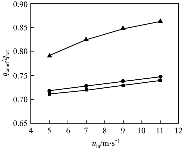
Figure 10 Ratio of condensation and total heat for different gap width■ 0.5 mm; ● 1.0 mm; ▲ 1.5 mm
For different gap widthb, the pressure drop ΔPat differentuinis showed in Fig. 11. Asuinincreases, ΔPincreases. Whenbincreases from 0.5 mm to 1.0 mm,the velocity through the gap increases, so the pressure drop increases at tape tip. Whenbchanges from 1.0 mm to 1.5 mm, the velocity decreases, so the pressure drop decreases.

Figure 11 Pressure drop versus mixture inlet velocity for different gap width■ 0.5 mm; ● 1.0 mm; ▲ 1.5 mm
3.4 Operating parameters
3.4.1Vapor fraction
For simulation conditions:uin=5 m·s-1,Tw=303 K,Tin=373 K, andxv,in=0.15-0.27. Fig. 12 showsqtotandqcond/qtot. Whenqconvchanges from 26.2 W to 27.7 W,qcondchanges from 71.8 W to 159.7 W, andqcond/qtotchanges from 73% to 85%.xv,inhas a significant effect onqcondbut has little effect onqconv. Fig. 13 shows that ΔPchanges from 94.6 Pa to 74.8 Pa, whiles friction factorfis constantly 0.22, since the flow velocity decreases when vapor condensation mass increases withxv,in.
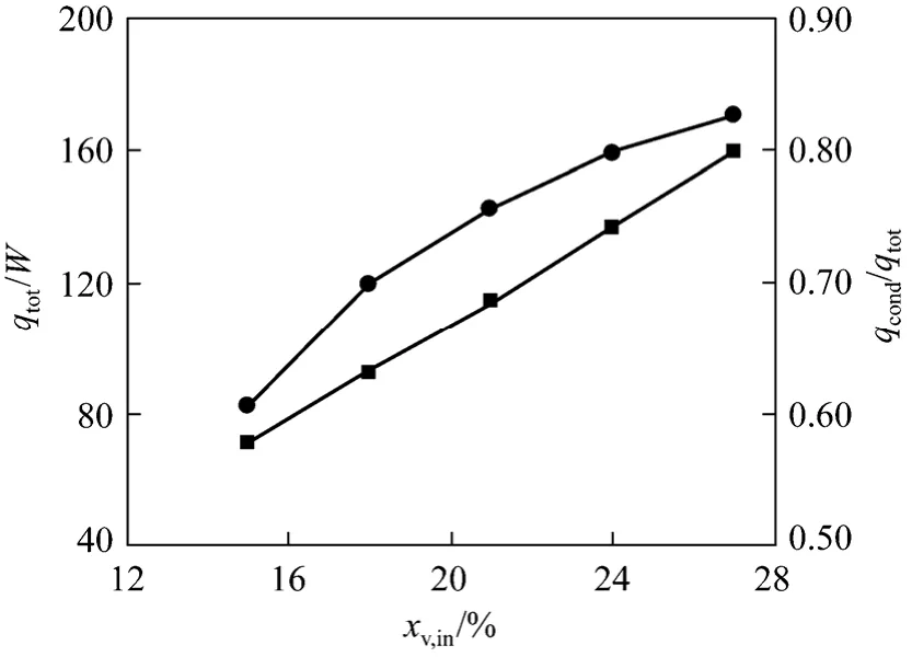
Figure 12 Ratio of condensation and total heat for different vapor inlet fractions■ total; ● ratio of condensation and total heat

Figure 13 Pressure drop and friction factor for different inlet vapor factions■ pressure drop; ● friction factor
3.4.2Wall temperature
With simulation conditions:uin=5 m·s-1,xv,in=0.15 andTin=373 K,Tw=303-323 K,qtotandqcond/qtotat different wall temperatures are shown in Fig. 14. AsTwincreases,qconvandqconddecrease, andqcond/qtotdecreases from 78% to 72%. ThusTwhas a significant effect on vapor condensation.
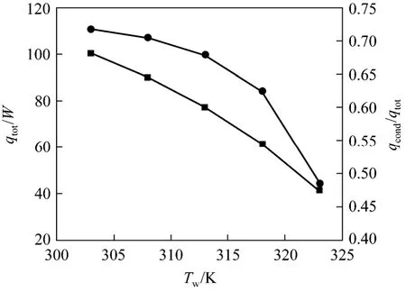
Figure 14 Total heat and ratio of condensation and total heat at different wall temperature■ total; ● ratio of condensation and total heat
3.4.3Inlet temperature of mixture
For simulation conditions:uin=5 m·s-1,xv,in=0.18 andTw=303 K,Tin=363-393 K, the effect of inlet temperature of mixture on the heat transfer is showed in Fig. 15. Whenqconvchanges from 22.8 W to 38.1 W,qcondchanges from 88.7 W to 97.1 W,qcond/qtotdecreases 80%-72%. WhenTinis increased 5 K,qconvrises 7%-10.2%, butqcondrise only 0.6%-2.1%. ThusTinmainly affectsqconvunder the conditions.

Figure 15 Condensation and total heat at different inlet mixture temperatures★ convective; condensation; ▲ total; ● ratio of condensation and total
4 CONCLUSIONS
The numerical solution of vapor surface condensation is presented with UDF of mass and energy sources, and compared with heat and mass transfer analogy and experiment test. The following conclusions can be drawn in the present study.
(1) The condensation model based on laminar species transport theory can be used to simulate vapor condensation with high concentration air. The condensation mass flux from condensation model is 5.5%-10.7% lower than experimental results. The pressure drop is between the results of experiment and heat and mass transfer analogy.
(2) As the gap width between the insert and tube increases, convection and condensation heat transfer increase first and then decrease, but the convection heat transfer increases sharply and then decreases slightly. From condensation and total heat transfer, the gap width of 1 mm is an optimal gap width.
(3) Increasing vapor fraction has a significant effect on condensation heat transfer while it has little effect on the convective heat transfer. Both convection and condensation heat decreases, the ratio of condensation and total heat decreases dramatically with the increase of wall temperature. Mixture inlet temperature mainly affects convection heat transfer.
NOMENCLATURE
Asurface or interface area, m2
bgap width between insert and wall, m
Ddiffusion coefficient, m2·s-1
ffriction factor
gmass transfer coefficient, kg·m-2·s-1
Hlatent heat of condensation, J·kg-1
hheat transfer coefficient, W·m-1·K-1
Jdiffusion flux, kg·m-2·s-1
llength of tube, m
Mmolecular mass, kg·mol-1
nvapor condensation flux, kg·m-2·s-1
Ppressure, Pa or kPa
qheat flux, W
Seenergy source
Sispecies mass source
Smmass source
Ttemperature, K
umixture velocity, m·s-1
Vcell volume, m3
Wvapor mass fraction, %
xvapor volume fraction, %
ydistance from cell center to the wall, m
δcondensate thickness, mm
λeffective condensation conductivity, W·m-1·K-1τshear stress
Subscripts
ave average
b bold
cond condensation
conv convection
i interface
in inlet
m mixture
out outlet
sat saturated
v vapor
w wall
1 Jia, L., Peng, X.F., Yan, Y., Sun, J.D., Li, X.P., “Effects of water vapor condensation on the convection heat transfer of wet flue gas in a vertical tube”,Int.J.Heat Mass Transfer, 44 (2), 4257-4265 (2001).
2 Brouwers, H.J.H, Van, C.W.M., “Heat transfer, condensation and fog formation in cross flow plastic heat exchangers”,Int.J.Heat Mass Transfer, 39 (2), 391-405 (1996).
3 Ajmal, S., Imran, R.C., Mansoor, H.I., “Numerical simulation of direct-contact condensation from a supersonic steam jet in subcooled water”,Chin.J.Chem.Eng., 18 (4), 577-587 (2010).
4 Ma, X.H., Chen, J.B., Xu, D.Q., Lin, J.F., “Heat transfer characteristics of dropwise condensation of steam on vertical polymer coated plates”,Chin.J.Chem.Eng., 9 (1), 17-21 (2001).
5 Wang, C.Y., Tu, C.J., Cai, L., Yan, L., “Condensation heat transfer of vapor-gas mixture in turbulent flow through an annulus”,Chin.J.Chem.Eng., 4 (2), 275-285 (1989).
6 Wen, L., Liang, M.Z., Zhang, H.W., Cheng, X.H., “Numerical simulation of steam condensation in vertical tube with the presence of non-condensable gas”,J.Shanghai JiaotongUniv., 43 (2), 299-303(2009).
7 Ivo, K., Miroslav, B., Borut, M., Ivan, B., “Modeling of containment atmosphere mixing and stratification experiment using a CFD approach”,Nuc.Eng.Des., 236 (14), 1682-1692 (2006).
8 Martin, F., Fernandez, J.A., Benitez, “Comparison of film condensation models in presence of non-condensable gas implemented in a CFD code”,Heat Mass Transfer, 41 (11), 961-976 (2005).
9 Volchkov, E.P., Terekhov, V.V., Terekhov, V.I., “A numerical study of boundary-layer heat and mass transfer in a forced flow of humid air with surface steam condensation”,Int.J.Heat and Mass Transfer,47 (6), 1473-1481 (2004).
10 Revankar, S.T., Pollock, D., “Laminar film condensation in a vertical tube in the presence of noncondensable gas”,Applied Mathematical Modeling, 29 (4), 341-359 (2005).
11 Krzysztof, K., “Mechanistic modeling of water vapor condensation in presence of noncondensable gases”, Ph.D. Thesis, Stockholm Univ., Sweden (2007).
12 Groff, M.K., Orimiston, S.J., Soliman, H.M., “Numerical solution of film condensation from turbulent flow of vapor-gas mixtures in vertical tubes”,Int.J.Heat and Mass Transfer, 50 (19), 3899-3912 (2007).
13 Chen, C.K., Lin, Y.T., “Turbulent film condensation in the presence of non-condensable gases over a horizontal tube”,Int.J.Ther.Sci.,48 (9), 1777-1785 (2009).
14 Riad, B., Salim, M., “Numerical analysis of filmwise condensation in a plate fin-and-tube heat exchanger in presence of non-condensable gas”,Heat Mass Transfer, 45 (12), 1561-1573 (2009).
15 Rao, V.D., Krishna, V.M., Sharma, K.V., Rao, P.V.J.M., “Convective condensation of vapor in the presence of a non-condensable gas of high concentration in a laminar flow in a vertical pipe”,Int.J.Heat and Mass Transfer, 51 (25), 6090-6101 (2008).
16 Yu, H., Zhu, J.H., Du, H.M., Xia, S.L., Guan, G.P., “Modeling and simulation of condensation and dehumidifying of high humidity industrial exhaust gases”,J.Chem.Ind.Eng., 56 (8), 1386-1389 (2005).(in Chinese)
17 Chen, Y.P., Wu, J.F., Shi, M.H., Zhang, C.B., Xiao, C.M., “Three dimension simulation for steady annular condensation in rectangular microchannels”,J.Chem.Ind.Eng., 59 (8), 1923-1929 (2005). (in Chinese)
18 Siow, E.C., Orimiston, S.J., Soliman, H.M., “A two-phase model for laminar film condensation from steam-air mixtures in vertical parallelplate channels”,Heat and Mass Transfer, 40 (5), 365-375 (2004).
19 Cui, Y.Z., Tian, M.C., “Three-dimensional numerical simulation of thermal hydraulic performance of a circular tube with edgefold-twisted-tape inserts”,J.Hydrodynamic, 22 (5), 662-670 (2010).
20 Cui, Y.Z., Tian, M.C., “Thermal and hydrodynamic performance of high humidity gas convection condensation in a tube with edgefold-twisted-tape”,CIESC J., 61 (12), 3092-3099 (2010). (in Chinese)
21 Peterson, P.F., Schrock, V.E., Kageyama, T., “Diffusion layer theory for turbulent vapor condensation with non-condensable gases”,ASME J.Heat Transfer, 115, 998-1003 (1993).
猜你喜欢
杂志排行

Chinese Journal of Chemical Engineering的其它文章
- Nanoparticle Migration in a Fully Developed Turbulent Pipe Flow Considering the Particle Coagulation*
- HPLC Analysis of Egg Yolk Phosphatidylcholine by Evaporative Light Scattering Detector
- A Geometric Approach to Support Vector Regression and Its Application to Fermentation Process Fast Modeling*
- Regeneration of Spent Activated Carbon by Yeast and Chemical Method*
- Removal of Organic Matter and Ammonia Nitrogen inAzodicarbonamide Wastewater by a Combination of Power Ultrasound Radiation and Hydrogen Peroxide*
- Optimization of Parameters for Melt Crystallization of p-Cresol*