多频带通滤波器技术*
2012-03-15褚庆昕陈付昌
褚庆昕 陈付昌
(华南理工大学电子与信息学院,广东广州510640)
0 Introduction
Emerging wireless standards result in new consumer systems,such as global system for mobile communication (GSM), wireless local-area network (WLAN),and worldwide interoperability for microwave access(WiMAX).The increasing demand for these applications in the communication market enables a single wireless system to support dualband or tri-band operations.Multiband bandpass filters are essential components of multiband systems.However,the conventional filter theory is based on the single-band assumption and it cannot be used to design multiband bandpass filters,so that novel technologies need to be developed for the design of multiband bandpass filters.
In recent years,several techniques for the design of multiband filters have been proposed,which are classified as the multi-passband resonator technique[1-6],the SIR(Stepped Impedance Resonator)technique[7-14],the SLR(Stub-Loaded Resonator)technique[15-22]and the assembled resonator technique[23-27].Lately,the authors have presented several effective and simple methods for the design of multiband filters,including the multi-passband resonators for obtaining independentlycontrollable passband characteristics[3-6],the two-and tri-section SIRs for minimizing the size of the multiband filter[10-14],the SLRs for acquiring conveniently-controllable passband frequencies[17-19,21-22],the assembled resonators for obtaining improved stopband rejection characteristics of the tri-and quad-band bandpass filters[24-27],and a novel multistub-loaded resonator for designing high-order dualband bandpass filters[28].In this article,the authors overview these technologies.
1 Multi-Passband Resonator Technology
The first multi-passband resonator technique is to combine two(or more)sets of different resonators with common input and output.In Refs.[3-6],two sets of resonators were employed in parallel configurations to design dualband filters,and desired center frequency and bandwidth at each passband were obtained.However,all the resonators are half-wavelength(/2)resonators,leading to a large size.
To achieve required bandwidth at each passband without increasing the circuit size,compact dual-and tri-band bandpass filters using/4 and/2 resonators were proposed[3].Fig.1 shows the geometry of the proposed dualband bandpass filter.The filter comprises two/4 hairpin resonators resonating at lower passbands and two/2 hairpin resonators resonating at higher passbands.All the resonators are employed in parallel configurations to obtain dual-passband responses.Therefore,the passband frequency and bandwidth of each passband can be controlled independently.As/4 resonators operate at lower passbands,the total size of the proposed filter is smaller than that of the filter using two sets of/2 resonators.

Fig.1 Layout of the proposed dualband filter using multipassband resonator[3]
An initial design example of the multi-passband resonator filter was presented in Ref.[3].Fig.2 shows the simulated and measured results of the dualband filter.The measured insertion losses(S21)in the two bands are respectively 1.1dB at 2.45GHz and 1.6dB at 5.25 GHz,while the measured return losses(S11) are respectively 16dB at 2.45GHz and 18dB at 5.25GHz, and the total size is less than 24mm×19.5mm,which means that this filter is smaller than the dualband filter using/2 stepped impedance resonators proposed in Ref.[10]with the same specification and substrate.

Fig.2 Simulated and measured S-parameters of the dualband filter using multi-passband resonator[3]
2 SIR Technology
2.1 Two-Section SIR Technology
Recently,more and more multiband filters have been realized with SIRs because of their multiband behavior[7-14].Fig.3 shows the basic structure of a twosection/2 SIR.

Fig.3 Geometric diagram of two-section SIR
The SIR consists of two lines of different characteristic impedances Z1and Z2and of electrical lengths θ1and θ2
[10].For simplicity,θ1is chosen to be equal to θ2,the fundamental resonance occurs at

where RZis the ratio of Z2to Z1,and θ0is the electrical length for fundamental frequency f0.The first spurious resonance occurs at

where θs1is the electrical length for the first spurious frequency fSB1.From Eqs.(1)and(2),one can obtain

It is clear from Eq.(3)that the spurious frequencies(fSB1,fSB2and fSB3)can be controlled by RZ,as shown in Fig.4.

Fig.4 Solutions of frequency ratios for different RZ

Fig.5 Simulated and measured S-parameters of the dualband filter using SIR[11]
To demonstrate the application of the SIR,a dualband filter operated at 2.4 and 5.7 GHz was designed[11],with an overall size of about 21mm×30mm. Fig.5 shows the S-parameter simulation and measurement results of the designed filter.The filter with the first resonant frequency of 2.4 GHz is of an insertion loss less than 1.2 dB and a return loss greater than 19dB,while for the second passband with a center frequency of 5.7 GHz,the insertion loss and the return loss are respectively less than 1.8 dB and greater than 16 dB.In addition,the proposed dualband bandpass filter can generate two transmission zeros,which provides a better cutoff rate in the stopband and gives much improved selectivity.
2.2 Tri-Section SIR Technology
To obtain tri-passband response,tri-section SIR was used to design tri-band filters[14-16].Fig.6 shows the structure of the tri-section SIR.As shown in Fig.6,the SIR is symmetrical and it comprises three different characteristic impedances Z1,Z2and Z3.And,for practical application,it is preferable to have equal electrical length for each section.The condition for the fundamental resonance of the tri-section SIR can be derived as follows:

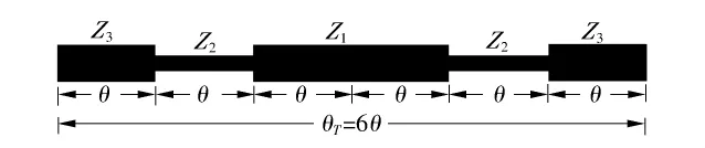
Fig.6 Geometric diagram of tri-section SIR[14]
It is clear form Eq.(4)that the spurious frequencies fSB1and fSB2can be controlled by tuning the characteristic impedance ratio RZ1(RZ1=Z3/Z2)and RZ2(RZ2=Z2/Z1),as shown in Fig.7.
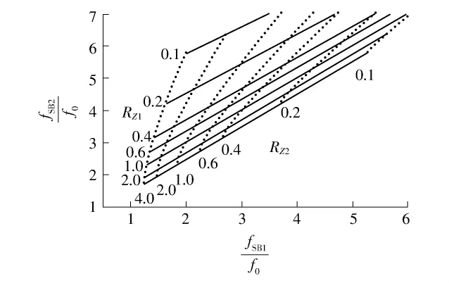
Fig.7 Solutions of frequency ratios for different RZ1and RZ2
Ref.[14]presented a tri-band microstrip bandpass filter(BPF)operated at 1.57-GHz GPS channel and 2.4/5.25-GHz WLAN bands.The building block used to construct this tri-band BPF comprises two pseudo-interdigital tri-section SIRs.By properly determining the impedance ratio of the tri-section SIRs,three passbands at the desired frequencies can be obtained,as shown in Fig.8.Each resonator has a hairpin structure,which makes the filter more compact.The BPF realized on a printed circuit board occupies an area of about 31mm×28mm.

Fig.8 Simulated and measured S-parameters of the tri-band filter using SIR[14]
3 SLR Technology
3.1 Single SLR Technology
Lately,multiband filters using SLR have become more and more popular,mainly because of their easilycontrolled resonant frequencies.Dualband(or triband)filters were designed using centrally-loaded resonators proposed in Refs.[15-22].In Ref.[20],the open-loop resonators loaded by shunt stubs were proposed to design compact high-order dualband filters.
The proposed resonator comprises a common microstrip half-wavelength resonator and an open stub shown in Fig.9(a),where L1and L2denote the lengths of the microstrip line and the short stub,respectively. The stub is shunted at the midpoint of the microstrip line.As the resonator is symmetrical to the T—T' plane,the odd-and the even-mode methods can be applied to analyze it.

Fig.9 Structure of SLR

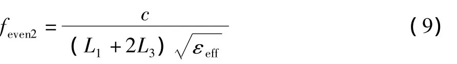
For open stub-loaded resoantor,the odd-mode resonant frequencies can be deduced as follows: where c is the light speed in free space,and εeffdenotes the effective dielectric constant of the substrate. It can be observed that the odd-mode resonant frequencies are not influenced by the stub.The even-mode resonant frequencies can be obtained as follows:

It can be observed that the even-mode resonant frequencies are determined by the lengths L1and L2as well as the impedance ratio.
For the short stub-loaded resonator shown in Fig.9(b),the resonant frequencies are respectively

By using the pseudo-interdigital short stub-loaded resonator,a dualband bandpass filter at 1.57/2.4GHz was developed[20].Fig.10 shows the corresponding simulated and measured results.The minimum insertion losses measured for the two passbands in the same sequence are respectively 0.7 and 0.5dB,and the return losses within the two passbands are both below-18dB.In addition,the proposed dualband bandpass filter can generate three transmission zeros,which provides a better cutoff rate in the stopband and gives much improved selectivity.The proposed filter is of a total size of less than 25mm×13mm.

Fig.10 Simulated and measured S-parameters of the dualband filter using SLR[17]
3.2 Short and Open SLR Technology
Refs.[18-19]presented a novel open and short stub-loaded crossed resonator and its applications to triband bandpass filters.Based on the lossless transmission line model analysis,it is found that the first three resonance frequencies of the crossed resonator can be conveniently controlled.Benefiting from this feature,the resonator can be utilized to design tri-band bandpass filters.The proposed resonator comprises a common microstrip half-wavelength resonator,a short stub and an open stub,as shown in Fig.11.

Fig.11 Structure of short and open stub-loaded resonator[18]
For odd-mode excitation,the first odd-mode resonant frequency can be deduced as follows:

For even-mode excitation,the first two resonant frequencies are respectively

In order to demonstrate the proposed concept,an experimental tri-band bandpass filter at 1.57,2.4 and 3.5GHz was developed in Ref.[18].Fig.12 shows the corresponding simulated and measured results.The minimum insertion losses measured for the three passbands in the same sequence are respectively 0.8,0.5 and 1.2 dB,and the return losses within the three passbands are all below-16dB.In addition,the proposed tri-band bandpass filter can generate transmission zeros on both sizes of the passbands,which gives much improved selectivity.The proposed filter is of a meandered open stub to reduce the circuit size and a total size of less than 33mm×13mm.

Fig.12 Simulated and measured S-parameters of the triband filter using SLR[18]
4 Assembled Resonator Technology
To obtain a tri-passband response based on the dualband filter layout[10],additional half-wavelength resonators are inserted,as illustrated in Fig.13.The proposed filter consists of two assembled resonators coupling in cascaded format,and each assembled resonator comprises a SIR(resonator A)and a common half-wavelength resonator(resonator B).Resonators A and B are placed together to form a compact structure without increasing the circuit size.Resonator A is designed to resonate at f1(the first passband frequency) and f3(the third passband frequency),and resonator B resonates at f2(the second passband frequency).

Fig.13 Layout of the proposed tri-band filter using assembled resonators[26]
Fig.14(a)shows the coupling structure of the triband filter,in which the solid lines represent the direct coupling routes.Resonators A and B are combined together to form an assembled resonator.As resonator A operates at two passbands,it can be divided into two resonators A1and A2.Resonator A1operates at the first passband and resonator A2operates at the third passband.So that the new coupling structure can be figured as Fig.14(b).Multi-path between the input and the output can be observed,which may introduce transmission zeros in the insertion loss response.

Fig.14 Coupling structure of the proposed tri-band filter[26]
Ref.[26]proposed a tri-band bandpass filter using the above-mentioned structure,and the corresponding simulated and measured frequency responses are shown in Fig.15.The minimum insertion losses measured for these three passbands are respectively 1.8,0.8 and 1.3 dB.The obtained transmission zeros are 2.19 and 2.64 GHz for the first passband,3.94 GHz for the second passband,and 4.58 and 5.70 GHz for the third passband,respectively.The total size is less than 24mm×22mm.

Fig.15 Simulated and measured S-parameters of the triband filter using assembled resonator[26]
To obtain quad-passband response,Fig.16 shows a novel assembled resonator for obtaining quad-passband response,which consists of two SIRs(SIRⅠand SIRⅡ)with different dimensions.SIRⅠis designed to resonate at f1(the first passband frequency)and f3(the third passband frequency),and SIRⅡresonates at f2(the second passband frequency)and f4(the fourth passband frequency).

Fig.16 Basic structure and components of an assembled resonator[27]
To increase the second spurious frequency of SIRⅠ,an open stub is loaded to the center of SIRⅠto adjust the resonant frequencies.The layout of the new structure is shown in Fig.17,and the open stub is meandered to reduce the circuit size.

Fig.17 Layout of the quad-band filter using assembled resonator[27]
Ref.[27]proposed a quad-band bandpass filter using assembled resonator.Fig.18 shows the corresponding simulated and measured frequency responses of the quad-band filter.The minimum insertion losses measured for these four passbands in the same sequence are 1.39,0.88,1.57 and 2.0 dB,respectively.The total size is less than 21.8mm×30.2mm,approximately 0.16g×0.23g,wheregis the guided wavelength on the substrate at the center frequency of the first passband.
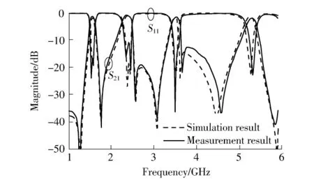
Fig.18 Simulated and measured S-parameters of the quadband filter using assembled resonator[27]
5 High-Order Dualband Filter
Recently,the authors presented several stub-loaded resonators for multiband bandpass filter application[17-19].The coupling between the stubs is added to obtain an extra degree of freedom in extracting coupling coefficients of the multiband filters,but these resonators are not suitable for building high-order filters. Based on their further investigation,the authors presented a novel multi-stub-loaded resonator suitable for high-order dualband filter applications[28].The novel resonator containing six open stubs(four fringe stubs and two center stubs)can be considered as a stubloaded SIR,as shown in Fig.19.It consists of many lines of different characteristic admittances(Y1,Y2,Y3)and of electrical lengths(θ1,θ2,θ3),so that the resonant frequencies of the proposed resonator can be conveniently controlled by tuning the stub parameters. The required bandwidth of the first passband is determined by the coupling between the fringe stubs,and the bandwidth of the second passband is dominated by the coupling between the center stubs,so that the characteristics of the two passbands can be controlled conveniently in wider ranges.As the six symmetric stubs can provide sufficient coupled sections between adjacent resonators,it is possible to build high-order dualband filters using the proposed resonators.The fabricated filter is of a size of about 80 mm×22 mm,approximately 0.93g×0.26g.

Fig.19 Structure of the multi-stub-loaded resonator[28]
The corresponding simulated and measured S-parameters are depicted in Fig.20.The minimum insertion losses measured for the two passbands in the same sequence are respectively 2.8 and 4.5 dB,which would be mainly attributed to the conductor and the dielectric loss.Below the first passband,minimum attenuation is 50dB from DC to 2.24 GHz.The two passbands are separated by a 50-dB stopband extended from 2.71 to 3.34GHz.

Fig.20 Simulated and measured results of the sixth-order dualband filter[28]
6 Conclusions
This paper summarizes some effective approaches to multiband filters,especially several techniques using microstrip technology,including the multi-passband resonator technique,the SIR technique,the SLR technique and the assembled technique.Moreover,the high-order dualband bandpass filter designed using the multi-stub-loaded resonators is also introduced.The proposed multiband bandpass filters are useful for multi-standard wireless applications and may attract more and more interests from both academia and industry.
[1] Chen C Y,Hsu C Y.A simple and effective method for microstrip dual-band filters design[J].IEEE Microwave Wireless Component Lett,2006,16(5):246-248.
[2] Chen C F,Huang T Y,Wu R B.Design of dual-and triplepassband filters using alternately cascaded multiband resonators[J].IEEE Trans on Microwave Theory Tech,2006,54(9):3550-3558.
[3] Chen F C,Chu Q X,Tu Z H.Design of compact dual-and tri-band bandpass filters using/4 and/2 resonators[J].Microw Opt Technol Lett,2009,51(3):628-631.
[4] Chu Q X,Ye L H.Design of compact dual-band bandpass filter using/4 resonators[C]∥Proceedings of Asia Pacific Microwave Conference.Hong Kong:IEEE,2008:1-4.
[5] Chu Qing-xin,Ye Liang-hua,Chen Fu-chang.Design of compact dual-band bandpass filter[J].Journal of South China University of Technology:Natural Science Edition,2010,38(6):7-10.褚庆昕,叶亮华,陈付昌.小型双频带通滤波器的设计[J].华南理工大学学报:自然科学版,2010,38(6):7-10.
[6] Chen F C,Chu Q X.Design of dual-band CT filter with source-load coupling[J].Journal of Electromagnetic Waves and Applications,2011,25(1):15-22.
[7] Kuo J T,Yeh T H,Yeh C C.Design of microstrip bandpass filters with a dual-passband response[J].IEEE Trans on Microwave Theory Tech,2005,53(4):1331-1337.
[8] Sun S,Zhu L.Compact dual-band microstrip bandpass filter without external feeds[J].IEEE Microwave Wireless Component Lett,2005,15(10):644-646.
[9] Zhang Y P,Sun M.Dual-band microstrip bandpass filter using stepped-impedance resonators with new coupling schemes[J].IEEE Trans on Microwave Theory Tech,2006,54(10):3779-3785.
[10] Chu Q X,Chen F C.A compact dual-band bandpass filter using meandering stepped impedance resonators[J]. IEEE Microwave Wireless Component Lett,2008,18 (5):320-322.
[11] Chu Q X,Chen F C.A novel dual-band bandpass filter using stepped impedance resonators with transmission zeros[J].Microw Opt Technol Lett,2008,50(6):1466-1468.
[12] Chen F C,Chu Q X.A compact dual-band filter using S-shaped stepped impedance resonators[C]∥Proceedings of International Conference on Microwave and Millimeter Wave Technology.Nanjing:IEEE,2008:1255-1257.
[13] Chu Q X,Lin X M.Advanced triple-band bandpass filter using tri-section SIR[J].Electronics Lett,2008,44 (4):295-296.
[14] Chen F C,Chu Q X.Compact triple-band bandpass filter using pseudo-interdigital tri-section stepped impedance resonators[J].Microw Opt Technol Lett,2008,50(9): 2462-2465.
[15] Zhang X Y,Chen J X,Xue Q.Dual-band bandpass filter using stub-loaded resonators[J].IEEE Microwave Wireless Component Lett,2007,17(8):583-585.
[16] Zhou M Q,Tang X H,Xiao F.Compact dual band bandpass filter using novel E-type resonators with controllable bandwidths[J].IEEE Microwave Wireless Component Lett,2008,18(12):779-781.
[17] Chen F C,Chu Q X,Tu Z H.Design of compact dualband bandpass filter using short stub loaded resonator[J].Microw Opt Technol Lett,2009,51(4):959-963.
[18] Chen F C,Chu Q X,Tu Z H.Tri-band bandpass filter using stub loaded resonators[J].Electronics Lett,2008,44(12):747-748.
[19] Chen F C,Chu Q X,Tu Z H,et al.A novel crossed resonator and its applications to bandpass filters[J]. IEEE Trans on Microwave Theory Tech,2009,57(7): 1753-1759.
[20] Mondal P,Mandal M K.Design of dual-band bandpass filters using stub-loaded open-loop resonators[J].IEEE Trans on Microwave Theory Tech,2008,56(1):150-155.
[21] Wu X H,Chu Q X,Tian X K.Dual-band bandpass filter using novel side-stub-loaded resonator[J].Microw Opt Technol Lett,2012,54(2):362-364.
[22] Chu Q X,Wu X H,Chen F C.Novel compact tri-band bandpass filter with controllable bandwidths[J].IEEE MicrowaveWirelessComponentLett,2008,21(12): 655-658.
[23] Lee C H,Hsu C I G,Jhuang H K.Design of a new triband microstrip BPF using combined quarter-wavelength SIRs[J].IEEE Microwave Wireless Component Lett,2006,16(11):594-596
[24] Chen F C,Chu Q X.Tri-band bandpass filter using assembled multiband resonators[C]∥Proceedings of Asia Pacific Microwave Conference.Hong Kong:IEEE,2008: 1-4.
[25] Chen Fu-chang,Chu Qing-xin.Design of triple-band filter based on assembled multiband Resonator[J].Journal of South China University of Technology:Natural Science Edition,2009,37(1):10-14.陈付昌,褚庆昕.基于组合多通带谐振器的三频滤波器设计[J].华南理工大学学报:自然科学版,2009,37(1):10-14.
[26] Chen F C,Chu Q X.Design of compact tri-band bandpass filters using assembled resonators[J].IEEE Trans on Microwave Theory Tech,2009,57(1):165-171.
[27] Chen F C,Chu Q X.Design of quad-band bandpass filter using assembled resonators[J].Microw Opt Technol Lett,2011,53(6):1305-1308.
[28] Chen F C,Chu Q X.Novel multistub loaded resonator and its application to high-order dual-band filters[J]. IEEE Trans on Microwave Theory Tech,2010,58(6): 1551-1556.
