内乘波式进气道与内型侧压式进气道性能分析
2011-04-19黄国平朱呈祥尤延铖
黄国平 朱呈祥 尤延铖 周 淼
(南京航空航天大学能源与动力学院,南京,210016,中国)
INTRODUCTION
Inlet is a very important part of hypersonic propulsion system.Traditional hypersonic inlet can be divided into three different types:2-D inlet,axisymmetric inlet and sidewall compression inlet[1].Among these inlets when used in fixed geometry, sidewallcompression inletalways shows better performance on inner flow characteristic and start ability according to past research.However,a new kind of inlet,inward turning inlet,has attracted people′s attention recently.Different types of inward turning inlet have already been investigated in worldwide range,such as Busemann[2],REST[3],JAW[4], Internal waverider inlet and so on.The concept of internal waverider inlet was first developed by authors.This newly research is also supported by National Natural Science Foundation of China in 2005.Yancheng You and Guoping Huang then put forward a section controllable internal waverider inlet concept on technology of streamline tracing, and obtained a Chinese invention patent[5].Simulations at design/off-design points and high enthalpy wind tunnel tests[6]were all performed by them.The results indicated that section controllable internal waverider inlet can obtain good performance.
The design of hypersonic inlets should match the following four requirements:high inner flow performance,low outer flow drag,starting ability,and compatibility of back pressure.For hypersonic inlet,the compatibility of back pressure is obtained by isolator.Then other three requirements are difficult to match simultaneously.In past decades,many researches were performed for development of sidewall compression inlets. So,most of researchers believe that sidewall compression inlet is a good choice for hypersonic aircrafts when they need fixed geometry inlets.But it cannot match the four requirements perfectly. Especially,the spillage of sidewall compression inlet is rather large,so the outer flow drag is large too.
The internal waverider inlet can decrease the spillage obviously.In order to show the advantage/disadvantage of internal waverider inlet, some researches on comparison between internal waverider inlet and sidewall compression inlet are performed in this paper.Under the same upstream flow condition,a typical internal waverider inlet with rectangular entrance and exit shape in front view,is designed according to the geometry parameters of a typical 3-D sidewall compression inlet.Simulation results at design/off-design points reveal the flow characteristics and performance of two different inlets.
1 MODELING ANDCALCULATION METHOD
1.1 Modeling of sidewall compression inlet
In order to do comparison between internal waverider inlet and sidewall compression inlet,a typical sidewall compression inlet mentioned in Ref.[1]is chosen as the simulation model.The length of this inlet is 707 mm.The width and height of entrance are 122 mm and 82 mm with a entrance area of 10 004 mm2,while that of exit are 50.5 mm and 34 mm with a exit area of 1 717 mm2.So the total contraction ratio is about 5.89, and the internal contraction ratio is 1.2.Fig.1 is the model of sidewall compression inlet.This inlet was presented in 2006 and was designed at Ma=6.0,H=25 000 m.The results of research on it show that it achieves relative high performance among sidewall compression inlet.Then, this paper constructs a model based on the data in Ref.[1],and uses this model to do numerical simulation.
Fig.1 Configuration of sidewall compression inlet
1.2 Modeling of internal waverider inlet
An internal waverider inlet with rectangular frontal shape entrance and exit is also designed at Ma=6.0,H=25 000 m,using the technology of streamline tracing and shock cutting[5].To ensure the comparability of the internal waverider inlet and the sidewall compression inlet,the contraction ratio of inlets should be same.Moreover,the new designed inlet has the same frontal shape of entrance.Although they have the same entrance shape,area and total contraction ratio,the exit shape of internal waverider inlet is rectangle while thatofsidewallcompression inletis nearly square.This is because the internal waverider inlet is a 3-D designing,so the streamline in each same angle θplane follows the same characteristics of basic flowfield,and the aspect ratio in exit plane is 1.48 which is almost the same as that of entrance plane.However,experience is more crucial when designing the sidewall compression inlet and attention is mainly focused on the assignment of pressure ratio.
The previous research[7]in internal waverider inlet design pointed out that a certain basic flowfield,ICFC,had the best uniformity and suited for the designing of internal waverider inlet better than other basic flowfields.So in this paper ICFC is chosen as the basic flowfield.Fig.2is the pressure ratio contours at symmetrical plane of ICFC basic flowfield under 2-D inviscid CFD simulation.

Fig.2 Pressure ratio contours of ICFC basic flowfield
Streamline tracing and shock cutting technology is adopted during the process of building inlet model. The basic theory of streamline tracing technology is setting a series of points at the en-trance or exit plane of ICFC basic flowfield according to the entrance or exit shape of inlet.3-D surface will be obtained when streamlines are created using these points,and through each point only one streamline can be acquired.This surface is actually just the shape of internal waverider inlet.Fig.3 is the entrance&exit schematic of internal waverider inlet.
Fig.3 Frontal view of inlet entrance&exit
With designing method listed above and preliminary viscous correction as well as shoulder smoothing,a 3-D internal waverider inlet with rectangular entrance&exit shape will be obtained (Fig.4).The length of this inlet is 822 mm.The width and height of entrance are 122 mm and 82 mm with a entrance area of 10 004 mm2,while of exit are 50.5 mm and 34 mm with a exit area of 1 717 mm2.So the contraction ratio is about 5.83.Those are as same as the sidewall compression inlet.
Fig.4 Configuration of internal waverider inlet
1.3 Calculation method
Flows in two inlets shown in Figs.1,4 are simulated numerically at design/off-design points.Several off-design points are simulated, such as:Ma=4.5,5.0,5.5,attack angles=±2°, ±5°,±8°and yaw angles=2°,5°,8°.All calculations are performed by using a CFD software,the NuAa′s Program for Aerodynamics(NAPA),operating on structured meshes.This software has been validated with lots of cases and proven to be effective for calculation of subsonic,transonic, supersonic and hypersonic inlets′internal and external flows[5-6].In this simulation,the Roe flux difference-split scheme is employed for the inviscid fluxes,together with the min-mod limiter.A standard central second-order scheme is employed for the viscous fluxes.The simulation is analyzed with the full 3-D steady Navier-Stokes equations together with a separation improved Baldwin Lomax(BL)turbulence model without body forces or external heat addition.The spatial accuracy used for all calculations is second order,with a three-step Runge-Kutta solution scheme.Given the high temperature effect,the variable specific heat thermally perfect gas model is used in the calculation[8].
2 FLOW AND PERFORMANCE OF TWO INLETS AT DESIGN STATUS
2.1 Flow of internal waverider inlet
The results of numerical simulation can show the flow structure of internal waverider inlet at design status.Fig.5is the pressure ratio contours in planeOA′&OC′(Fig.3)of internal waverider inlet.The initial shock is induced at the entrance when free upstream comes into the inlet,and reflects at the upper surface.It almost covers the whole entrance area of inlet,which makes high flow capture ratio possible.In Fig.3,OA′is the symmetric plane while OC′is the half-diagonal plane.The same angle θplane OC′includes the cross line between upper surface and side surface. Comparison between two contours indicates that OC′plane has the similar shock structure as OA′plane,even if OC′is effected by upper and side surfaces together.This is also the contribution of internal waverider inlet designing method.Although the shock structure is similar to the basic flowfield in both planes,we can still find out that the initial shock does not attach the cowl lip completely.As a result,there will still axist tiny spillage.Fig.6depicts the total pressure recovery contours at the exit plane of inlet.Parameters at the exit plane are divided obviously into upper and lower parts.As a result of the long distance of lower surface as well as the shock wave-boundary layer interaction,the thickness of boundary layer at the exit plane is rather considerable.This lowenergy region will further lead to the low total pressure recovery.From the right contour,total pressure recovery is still high at two corners near the upper surface.It can be concluded that energy losing is not serious at these corners.The total pressure recovery of more than half of the exit is larger than 0.4.

Fig.5 Pressure ratio contours of internal waverider inlet

Fig.6 Total pressure contours of internal waverider inlet
Fig.7 is the surface pressure ratio distribution in the symmetric plane.Before getting into the isolator,incoming flow should get through a series of isentropic compression.In the exit plane of inlet,pressure ratio at upper surface is close to that of lower surface.This phenomenon is coherent to the goal of developing ICFC basic flowfield[7].In isolator,pressure ratio at upper surface and lower surface rises alternately as a result of the shock reflection.
Fig.7 Pressure ratio distribution of internal waverider inlet
2.2 Flow of sidewall compression inlet
Although the model of sidewall compression inlet is selected from Ref.[1],this paper still calculates the flow characteristics under different incoming flow conditions for data restoring.Fig.8 is the pressure ratio contour at symmetric plane of sidewall compression inlet.Shock wave religion from bottom board and sidewall intersects with each other,and forms a spillage window in the symmetric plane.The flow is spilled from this window.Additionally,oblique shock wave created by the cowl lip will reflect and interact with boundary layer for several times in isolator.At shoulders of bottom board,rarefaction waves will be created,and intersect with the oblique shock wave and reflect as well.These rarefaction waves can weaken the inlet pressure ratio.Fig.9 depicts the total pressure recovery at the exit plane.As sidewall compression inlet can produce 3-D compression effect only through sidewall,so the bad corner flow created by bottom board and sidewall is inevitable.This will not only generate the vortex structure at the corners near lower surface, but also will decrease the total pressure recovery. At the mainstream area of exit plane,the total pressue recovery is 0.55 while that of internal waverider inlet is 0.61.The area with larger than 0.4 total pressure recovery,is less than half of the exit.
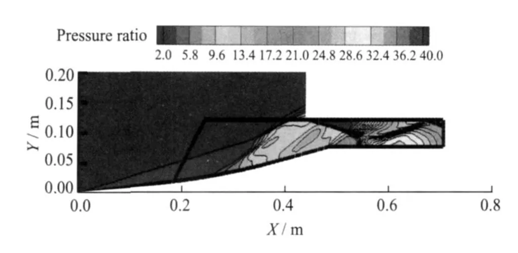
Fig.8 Pressure ratio contours of sidewall compression inlet

Fig.9 Total pressure recovery contours at exit plane

Fig.10 Pressure ratio distribution of sidewall compression inlet
Fig.10 is the surface pressure ratio distribution in symmetric plane of sidewall compression inlet.At outer contraction part,a bit isentropic compression exits due to the part of arc bottom board.At the cowl lip,pressure rises up quickly owe to the oblique shock wave there.Furthermore,pressure fluctuates at the upper surface in a short distance from the cowl lip.From the left small picture in Fig.9,we can observe that shock waves created by sidewall intersect with each other in inner contraction part and reflect for several times.At the exit plane of inlet,pressure of upper surface is evidently different from lower surface,which means that the uniformity is lower than that of internal waverider inlet.
2.3 Performance parameters of two inlets at design point
Table 1 is the comparison of performance between two inlets.Internal waverider inlet can capture most of the incoming flow and the flow capture coefficient is 0.98.This is also the main advantage of internal waverider inlet.On the contrary,the flow capture coefficient of sidewall compression inlet is only 0.845.More than that, average pressure ratio at exit plane of internal waverider inlet is 29 while sidewall compressioninlet is 25,and internal waverider inlet holds a higher total pressure recovery even if with a higher pressure ratio.Additionally,average Mach number at exit plane of internal waverider inlet is lower than that of sidewall compression inlet,which will delicate to the performance of combustor.Kinetic efficiency of internal waverider inlet is also a bit higher.In general,the main advantages of internal waverider inlet are high flow capture coefficient and better internal flow performance.
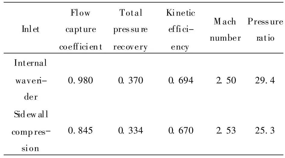
Table 1 Comparison of performance between two inlets at design point
3 PERFORMANCE AT OFF-DESIGN STATUSES
Several off-design flows of both two inlets are simulated.Those off-design statuses include different attack angles, yaw angles,and upstream flow Mach numbers.
3.1 Performance parameters of two inlets at off-design statuses
Table 2 provides a summary of performance of two inlets at off-design status.Internal waverider inlet has good performance in flow capture ability.At yaw angle 8°or attack angle 8°,it can capture more than 92% or 94% of upstream even.Under same conditions,the sidewall compression inlet can capture only 79% of upstream. When upstream flow Mach number decreases to 4.5,the flow capture coefficient of internal wa-verider inlet is 92%,and the one of the sidewall compression inlet is 72%.This value of internal waverider inlet increases almost 28% than sidewall compression inlet.In most cases,the internal waverider inlet owns obvious better performance than sidewall compression inlet,while the pressure ratio of internal waverider inlet is a bit higher.In addition,flow characteristics of internal waverider inlet at off-design points do not deteriorate evidently,and average Mach number at exit plane of internal waverider inlet is a bit lower.That is a good thing for combustor working.

Table 2 Comparison of performance parameters for two inlets at off-design points
3.2 Off-design Mach numbers
The off-design Mach numbers tested by numerical simulation include 4.5,5.0 and 5.5,and two inlets can still work properly under these conditions.Fig.11 is the total pressure recovery contours at off-design Mach numbers of two inlets.As shown in Fig.11,the characteristics of total pressure distribution are similar even under different Mach numbers in each inlet.Comparing the parameters of two inlets in exit plane at Ma= 5.0,total pressure recovery of internal waverider inlet is a bit higher.In another hand,although sidewall compression inlet is also a 3-D compression inlet,the flow structures are worse than internal waverider inlet.So,that will lead to the deterioration of parameters in exit plane.
The start abilities of two inlets also are compared preliminarily.The un-start Mach number of internal waverider inlet is 3.3,while it is 2.9 of sidewall compression inlet.The start ability of sidewall compression inlet is bit higher.However,as analyzed previously,better start ability of sidewall compression inlet is obtained at the cost of large loss of performance.Internal waverider inlet also have better start performance when some geometry parameters are adjusted like the first shock angle as well as with high flow capture ability at off-design points.
3.3 Variable attack and yaw angles
Performance at attack angles±2°,±5°,±8° attack angles are analyzed in this paper.Fig.12 presents the total pressure recovery contours in exit plane under 5°.Compared flows between two inlets,we find that the total pressure in main-stream area is a bit higher in internal waverider inlet.But the distortion is also higher because of the narrow shape of exit plane,especially near the bottom board there existing large low-energy area.
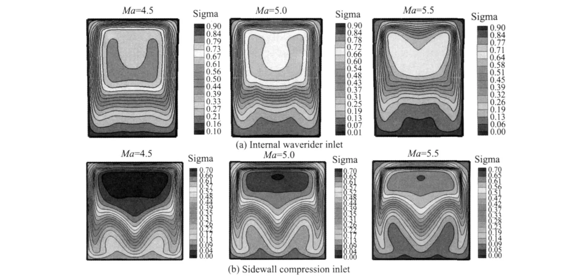
Fig.11 Total pressure recovery contours at exit plane of two inlets with different Mach numbers
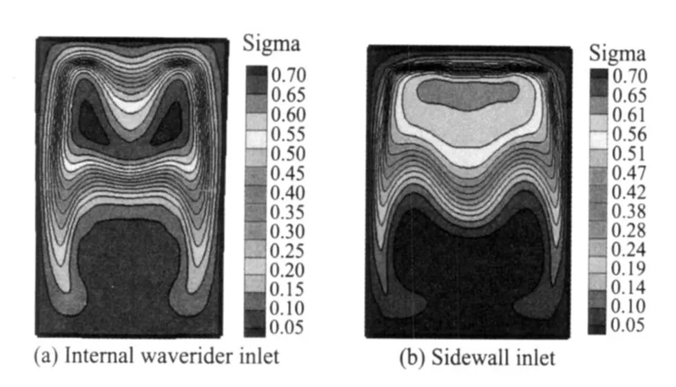
Fig.12 Total pressure recovery contours at exit planes of two inlets with attack angle5°
When the yaw angle increases,the flow structure at exit becomes more and more dissymmetric.Low-energy area moves to the left side of exit plane due to yaw angle affection,and has a tendency of becoming larger.Taking internal waverider inlet for example,at yaw angle 8°,highenergy area is finite compared with that of yaw angle 2°.and the total pressure recovery is only 0.51.Additionally,low-energy area at the bottom of exit plane has a tendency of moving upward besides leftward.Fig.13 is the shockwave shape in cross section at x=410 mm.The shock is forced to the right side. In addition,the spillage flow becomes relative large when yaw angle increases.However,even in the case with yaw angle 8°,the shockwave covers most of the entrance of internal waverider inlet.So,this lets the new inlet have a very high flow capture coefficient.

Fig.13 Mach number isolines of internal waverider inlet at cross section of x=410mm
4 CHARACTERISTICS OF TWO INLET DESIGNS
Internal waverider inlet and sidewall compression inlet both belong to 3-D compression inlet.They have obvious 3-D flow characteristics, but the design concept is different distinctly.
The design concept of internal waverider inlet is to create the inlet model from shock structure and performance parameters.In this work, an ICFC basic flowfield is designed first,and then the streamlines are traced in all same angle planes from ICFC.Shockwave shape in cross section is also arc,the same as basic flowfield.Fig.14 is the schematic of streamline tracing from different inlet entrance points.This design method can ensure the shock shape in inlet being the same as basic flowfield,and avoid complex interaction among 3-D shock waves.Although the geometry parameters and shape of internal waverider inlet are similar to those of sidewall compression inlet, the performance is better.

Fig.14 Schematic of streamline tracing of IW R inlet
The design concept of sidewall compression inlet is from geometry model to calculate the performance parameters.It is a process of modulation to satisfy the design requirements. The shock shape in cross section of sidewall compression inlet is made up of one bottom shock wave and two sidewall shock waves.It is just a combination of 2-D shock waves.Fig.15 shows the shockwave shapes of two inlets.From Fig.15 we can find that sidewall compression inlet has not only corner flows,but also spillage flows from upside of sidewall.At the downstream part of the sidewall,this spillage becomes large and large.
It is well known that more flow capture means more thrust to hypersonic propulsion system with a certain area of frontal shape,and means less drag induced by spillage.So the great flow capture ability under different conditions is the extraordinary advantage of internal waverider inlet,because it rides the shockwave at entrance.
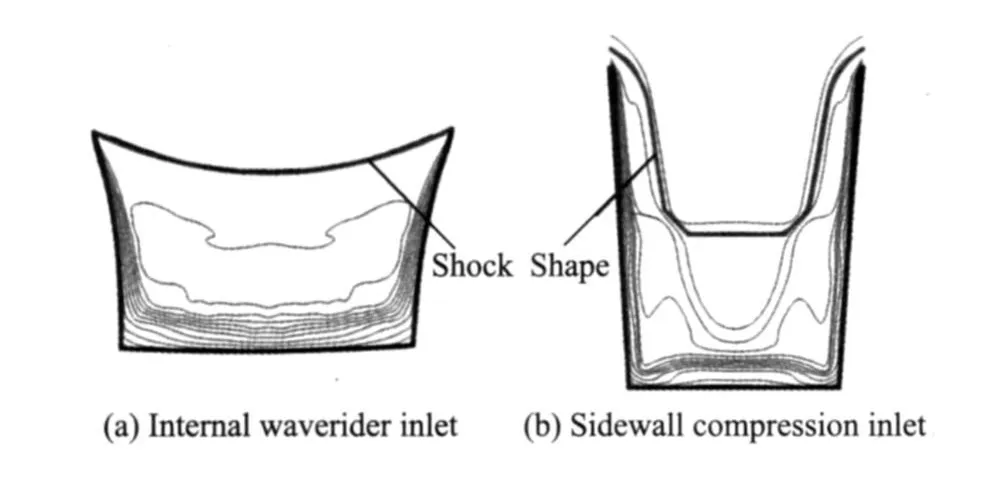
Fig.15 Shock shape of two kinds of inlets
5 CONCLUSIONS
In the paper,a new internal waverider inlet with rectangular shape of entrance and exit is designed according to the geometry parameter of typical sidewall compression inlet.Comparisons between the two inlets show that:
(1)At design status,the bad corner flow is less in internal waverider inlet,while such corner flow of sidewall compression inlet is large.And the sidewall compression inlet has complex shockwave intersections with each otherand with boundary layer.So,total pressure recovery in exit plane of internal waverider inlet is higher. Compared with parameters of sidewall compression inlet,total pressure recovery in exit plane of internal waverider inlet is almost 11% higher, flow capture coefficient is 16% higher,pressure ratio is 16% higher,and Mach number in exit plane is 1.3% lower.Each parameter is better than sidewall compression inlet,especially the flow capture coefficient.
(2)At off-design statuses,the differences of performance between two inlets are similar to design status.The internal waverider inlet achieves better performance than sidewall compression inlet.Especially,the flow capture coefficient of internal waverider is 16%—28% larger than the one of sidewall compression inlet in off-design statuses.The un-start Mach number of internal waverider inlet designed in this paper is 3.3,while that of sidewall compression inlet is 2.9.
(3)The internal waverider inlet has good performance.It can obtain better inner flow performance,low outer flow drag,and good starting ability simultaneously.Moreover,it can achieve very high flow capture coefficient(for example: 0.98 at design status).Internal waverider inlet has such great flow capture ability because it rides the shockwave at entrance.
[1] Jin Zhiguang,Zhang Kunyuan.An efficient method for increasing mass flow capture ratio of a three-dimentional sidewall compression scramjet inlet[J]. Journal of Aerospace Power,2006,21(5):897-902.
[2] Jacobsen L S,Tam C J,Robert B F.Starting and operation of a streamline-traced busemann inlet at Mach 4[C]∥42nd AIAA/ASME/SAE/ASEE Joint Propulsion Conference& Exhibit.[S.l.]:AIAA, 2006:AIAA 2006-4508.
[3] Smart M K,Trexler C A.Mach4performance of a fixed-geometry hypersonic inlet with rectangular-toelliptical shape transition[C]∥41st Aerospace Sciences Meeting and Exhibit.Reno,Nevada:AIAA, 2003:AIAA2003-0012.
[4] Malo F J,Gaitonde D V.Analysis of an innovative inward turning inlet using an air-JP8 combustion mixture at mach7[C]∥36th AIAA Fluid Dynamics Conference and Exhibit.San Francisco,Califorlia: [s.n.],2006:AIAA 2003-3041.
[5] You Yancheng,Huang Guoping,Guo Junliang,et al.Design method of hypersonic internal waverider inlet with controllable shape of intake and exit[P]. Chinese Patent of Invention,ZL2008101558987.X.
[6] You Y,Liang D,Design concept of three-dimensional section controllable internal waverider hypersonic inlets[J].Science in China(Series E),2009,52 (7):2017-2028.
[7] Guo Junliang, Huang Guoping, You Yancheng, et al.Study of internal compresion flowfield for improving the outflow uniformity of internal waverider inlet[J].Journal of Astronautics,2009,30(5): 1934-1940.
[8] You Yancheng.A new understanding of the nonlinear eddy-viscosity distribution for the two-dimentional separation flows[J].Acta M echanica Sinica, 2009,41(2):145-154.