CFD Simulation of Flow and Mass Transfer in Structured PackingDistillation Columns*
2009-05-14ChenJiangbo陈江波LiuChunjiang刘春江YuanXigang袁希钢andYUGuocong余国琮
Chen Jiangbo (陈江波), Liu Chunjiang (刘春江), Yuan Xigang (袁希钢) and YU Guocong(余国琮)
CFD Simulation of Flow and Mass Transfer in Structured PackingDistillation Columns*
Chen Jiangbo (陈江波), Liu Chunjiang (刘春江), Yuan Xigang (袁希钢)**and YU Guocong(余国琮)
State Key Laboratory for Chemical Engineering (Tianjin University), Chemical Engineering Research Center and School of Chemical Engineering and Technology, Tianjin University, Tianjin 300072, China
structured packing, two-phase flow model, mass transfer, height equivalent to a theoretical plate
1 Introduction
Structured packing columns are widely used in chemical, biochemical, and petrochemical industries. It has been found that the flow pattern on different scales is of great importance in determining the process performance that using structured packing as their equipment internals [1, 2]. Detailed investigation of the fluid dynamic behavior becomes essential for predicting the process performance and for developing more effective and optimal equipment internals.
In recent years, many numerical researches that using computational fluid dynamic (CFD) techniques to investigate the hydro/aerodynamic behavior in structured packing columns have been carried out. Among them, the work of Hodson. [1] may be the first published paper which using CFD method to investigate the performance of structured packing. The flow pattern of the vapor phase on the micro-scale within the channels of the structured packing was simulated. For simulating the hydrodynamics of liquid phase flow in structured packing filled with catalyst pellets, van Gulijk [2] presented a Toblerone model, simplified the multiphase flow to a single phase in the channels, and calculated the transversal dispersion in the structured packed bed using the CFX code. On the basis of van Gulijk’s work, the group of Krishna [3-5] carried out a number of experimental and theoretical studies on investigating the flow and mass transfer behavior within a KATAPAK-S structure packed with catalyst. The residence time distribution and mass transfer in liquid phase [3], radial and axial dispersion [4], and the mass transfer in gas and liquid phases [5] were investigated by CFD method. In the research of Klöker. [6-8], they proposed an innovative approach for the design of reactive distillation column internals and CFD simulations were regarded as virtual experiments for providing the necessary hydrodynamic and mass- transfer correlations. For predicting the dry pressure drop of structured packing column, Petre. [9] and Larachi. [10] proposed a combined mesoscale- microscale predictive approach, in which the structured packing could be decomposed into five types of representative units (REUs). By calculating the aerodynamics in each REU by CFD method, the pressure loss coefficient in each particular REU could be obtained and the total bed pressure drop could be calculated. Based on Petre and Larachi’s work, Raynal. [11] investigated the influence of mesh size and turbulence models when using CFD method to predict the dry pressure drop of structured packing. For simulating the flow behavior of the liquid phase, Zhang. [12, 13] proposed a volume-averaged CFD model for the liquid flow behavior in a structured packing column where the gas phase was stationary. In their work, the axial backmixing coefficient of the liquid phase was evaluated. It should be noted that most of the literatures mentioned above were using single or quasi-single phase flow model to simulate the flow behavior.
Till date, only a few reports that using CFD method to simulate two-phase flow within the packed column could be found in the literatures. Based on the volume-averaged method, Iliuta. [14, 15] developed a one-dimensional two-zone two-fluid mechanistic model to predict the irrigated two-phase pressure drop, the total liquid holdup and the packing fractional wetted area in countercurrent columns containing structured packing. Utilizing CFX code, Yin. [16, 17]simulated the hydrodynamics and mass-transfer processes of gas-liquid two-phase flow in randomly packed distillation columns by solving volume averaged Navier-Stokes equations. For simulating the macroscale multiphase flow behavior in packed column, Jiang. [18, 19] developed a new strategy for flow modeling in packed beds by implementing the statistical description of the bed structure into the Eulerian-fluid CFD model. Using the proposed method, the gas-liquid cocurrent down-flow system was investigated. In the work of Yuan. [20], CFD analysis of two-phase cross/countercurrent flow in the packed column with a novel internal was carried out. Their results showed that the installation of the internal in the packed column significantly reduces the pressure drop and improves operational flexibility. It should be pointed out that almost all the multi-phase flow studies reviewed above were modeling on the macroscale perspective.
For detailed investigation of the multi-phase flow behavior in structured packing, some microscale studies were carried out using VOF method. Among them, Szulczewska. [21] and Gu. [22, 23] investigated the falling film flow on the corrugated plate, corresponding to the surface texture of structured packing. Effects of the plate microstructure, liquid viscosity, surface tension and gas flow velocity on liquid flow pattern were investigated. Also using VOF method, Raynal. [11] estimated the liquid film thickness in a 2D geometry, corresponding to a vertical cross section of the packing. Hoffmann. [24] investigated the two and three phase film flow behavior for the packing. For three-phase flows, their qualitative comparisons showed good agreement of simulations with experiments. Using semi-analytical and CFD techniques, Valluri. [25, 26] investigated the dynamic evolution of films over an industrial structured packing surface at moderate Reynolds numbers. In their work, CFD was used as virtual experiment to verify the semi-analytical model. In the paper of Ataki and Bart [27], flat packing element of Rombopak4M was investigated. CFD simulation results were used as a basis to derive or modify correlations to describe the degree of wetting, the effective area and the liquid holdup for the Rombopak4M packing. It should indicate that most of the above mentioned investigations were restricted to falling film flow on the plates.
It appears from above review that most of the published studies were restricted to fluid dynamic simulations,.., predicting the flow pattern, pressure drop, liquid holdup and distribution behavior. There are few reports on predicting the mass transfer efficiency in the structured packing distillation column by CFD method. Based on our previous work [22, 23], a three-dimensional two-phase flow model for the simulation of hydrodynamics in a typical representative unit in structured packing by the VOF approach is proposed. Combined the CFD model with mass transfer equations, detailed behavior of mass transfer process in the REU is simulated and the calculated separation efficiency is compared with experiments.
2 Numerical simulation procedure
2.1 Model development
According to Petre. [9], the complex geometry of structured packing can be considered as the combination of five typical representative units (REUs), among which the most typical one is the criss-crossing junction REU. Since the mass transfer occurs in the inner part (criss-crossing element) of the packing, we focus our attention only on this type of unit in the present study.
The computational domain is shown in Fig. 1. Its sizes correspond to the geometry of the structured packing used in our previous experiment [28, 29]. The simulated domain used here is a little different from the criss-crossing REU of Petre[9]. The model used by Petre consisted of two channels. In our model, however, four channels are considered, two of which are reversely positioned with the others. The effect of different channels on the fluid dynamic behavior can be described more practically than REU model, especially for liquid phase flow. Besides, the boundary conditions on the open side of the channels, which is very complex to determine in Petre’s model, can be avoided. For wall boundaries, the surface of the packing was assumed to be smooth. In the simulations, we assumed that the system was isothermal and the fluids were incompressible.

Figure 1 Physical model for the three-dimensional CFD model of criss-crossing representative unit of corrugated- sheet structured packing
2.2 Mathematical model
The hydrodynamic model and its closure equations used in the present study were similar to our previous investigations [22, 23], so detailed description of the model and VOF method was omitted here. It should be pointed out that, in our previous work, only the 2D flow falling from the surface of the plates was investigated. In present work, the 3D flow behavior in the REU domain that enveloped by two corrugated plates was numerically calculated. In the work of Raynal. [11], the RNG-model was proved to be more suitable to this structure than the standard-model and the realizable-model. Thus in our study, the RNG-model was used to describe the turbulent flow characteristics in the structured packed bed.
In order to predict the mass transfer efficiency of structured packing by CFD method, the mass transport equations for different components must be solved simultaneously with momentum equations. Here the mass transport equation is expressed as

The effective mass diffusivity coefficients for both phases [the subscribeis omitted in Eqs. (2)-(6)] are given by


in which the constants are [31]

The interphase mass transfer rate for binary distillation is calculated according to the two-film theory,


whereis the relative volatility. Combining Eqs. (7)-(9), the interphase mass transfer rate can be calculated.
In Eqs. (7) and (8), the mass transfer coefficients of gas and liquid phase, and the effective interfacial area are calculated using the correlations of Rocha. [32] and Gualito. [33],
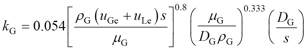


whereGeandLeare gas and liquid effective velocity, respectively, and are correlated as ,


andis the contact angle between liquid phase and solid surface of packing


2.3 Initial and boundary conditions
Initially, the computational domain is filled with gas and the volume fraction of the liquid is set to zero.


2.4 Simulation scheme
In the simulations, the CFD code, Fluent, is used to solve the model equations. The calculations are carried out under the unsteady state until pseudo-steady conditions are reached, which are characterized by a constant mass-weighted-averaged mass fraction of-butane at the liquid outlet. Additionally, the mass flow rates at outlets do not vary with time and is equal to the inlet mass flow with less than 5% error. Fig. 2 illustrates a typical trend of the mass-weighted-averaged mass fraction of-butane at the liquid outletthe flow time, obtained according to the calculation results. Generally, the time step is set lower than 0.0001 s, typically 0.00005 s. The first order upwind differencing is chosen as the solution of the momentum equation and species transport equation. For the simulations, PRESTO! Pressure interpolation scheme is adopted, and PISO is taken as recommended for pressure-velocity coupling.

Figure 2 Mass-weighted-averaged mass fraction of-butane at the liquid outletflow time
3 Results and Discussion
By CFD simulation, the flow patterns of both phases and the concentration distribution of the components can be obtained. Using the volume fraction of the phases, the liquid holdup and the wetted area can be calculated. Using the concentration distribution of the component, the separation efficiency [height equivalent to a theoretical plate (HETP)] can be estimated. To validate the proposed method, empirical correlations and experimental data [28, 29] are compared with the simulated results.
3.1 Liquid holdup
For validating the CFD model, the liquid holdup and wetted area are compared with the values predicted by the correlation presented by Gualito[33]. Fig. 3 (a) shows the simulated liquid distribution in the REU obtained at thevof 1.025 m·s-1·(kg·m-3)0.5under 1.4 MPa. In details, the liquid distribution on three sections and open sides of the channels are presented in the Fig. 3 (b) and 3 (c), respectively. It can be seen that, as the assumption made in many empirical models [32, 33], the liquid flows through the structured packing mainly in the form of continuous film, with a few drips scattered on the surface. Besides, it is also found that the film surface is not smooth, but covered by ripples, and the liquid film thickness varies as it flows down, which is possibly the results of increasing interaction between the gas and the liquid.


By integrating the mass of the liquid phase in the REU, we can calculate the volume of different phases, and further the liquid holdup. The calculated liquid holdup results at 0.6-1.8 MPa are given in Fig. 4, in which the values predicted by Gualito model are also provided for comparison. Both models can predict the increasing trend as the vapor flow rate increases, which is caused by the increase of both liquid flow rate and the interaction between the gas and the liquid. At 0.6 MPa, the values of liquid holdup predicted by present CFD model are very close to those predicted by the Gualito model, but at the pressures above 1.0 MPa, the former are about 1-2 times higher than the latter.

Figure 4 Comparison of liquid holdup predicted by the present CFD model and Gualito model [33]□ simulated by CFD model;■ predicted by Gualito model
3.2 Wetted area
It has been accepted that the wetted area, or the wetted fraction of the packing surface, is very important for determining the mass transfer behavior in the structured packing columns. However, in reality, the wetted area is different from the effective interfacial area. Under some particular conditions, the effective interfacial area is considered to be approximately equal to the wetted area. Under high pressure distillation conditions, however, the film surface is covered by many ripples as shown in Fig. 3, which makes the effective interfacial area unequal to the wetted area. Fig. 5 illustrates the comparison of the wetted area calculated by present CFD model with the effective interfacial area predicted by Gualito model. The trends of two results are roughly the same, that is, both increase with the vapor load, and all values are less than 1. However, the two predicted results are a little different in magnitude. At 0.6MPa, the wetted area is smaller than the effective interfacial area. At the pressure above 1.4MPa, the former becomes higher than the latter. This indicates that the operating pressure has greater effect on the wetted area than that on the effective interfacial area. It is possibly caused by the reason that, with the increase of operating pressure, the increasing interaction between the gas and the liquid phase leads to the increase of the wetted area.
3.3 Separation efficiency
The separation efficiency is compared with the experimental data [28, 29]. The experiments were carried out in a packed column with the internal diameter of 150 mm at pressures of 0.6-1.8 MPa, under total reflux operation. The packing was Mellapak 350Y, and the system was-butane/-butane mixture. In the simulation, it was assumed that the gas- and liquid-phase are uniformly distributed in the packed bed. Fig. 6 (a) shows the simulated concentration distribution obtained at thevof 1.025 m·s-1·(kg·m-3)0.5under 1.4 MPa. It is clearly seen that the mass transfer rate in different sections is not the same. At the position where the gas-liquid interface waves intensely, the concentration gradient of-butane in the liquid phase is higher, which means that the mass transfer rates are relatively higher.

Figure 5 Comparison of the wetted area calculated by present CFD model with the effective mass-transfer area predicted by Gualito model □ calculated by CFD model;■ predicted by Gualito model
According to the simulated concentration distribution, the mass-weight-averaged concentration of-butane at the liquid outlet can be calculated, and then by the Fenske equation, the separation efficiency (HETP) is estimated. Fig. 7 gives the simulation results and experimental data under different conditions. By comparison, it is found that the present CFD model predicts the similar trend as the experimental data, with an average absolute deviation (AAD) of 25.4%. Generally, the model under-predicts the HETP for most the-factors studied because only criss-crossing REU is included in the computational domain, while other REUs, such as the 2-layer transition REU, the channel-wall transition REU and the entrance region REU (as given in the literature of Petre. [9]), are not taken into account in the simulations. It is reasonably accepted that the separation efficiencies in these REUs are relatively lower than that in the REU considered in this CFD model.
In Fig. 7, the predicted HETPs from Gualito model are also provided for comparison. Contrary to the trend of experimental results, the HETPs predicted by Gualito model slightly increase with the increase ofv. Besides, the predicted HETPs from empirical correlations deviate more greatly from the experimental data than those predicted by present CFD model under each operating pressure. As a result, the CFD model presented in this paper can offer a better prediction of mass-transfer efficiency than Gualito model under the conditions investigated.

Figure 7 Comparison of HETP predicted by different models at different pressures■ experimental data;□ simulated by CFD model;○ predicted by Gualito model
4 Conclusions
Nomenclature
eeffective interfacial area, m2·m-3
pspecific surface area of packing, m2·m-3
concentration
LT,GTtotal molar concentration of-butane in the liquid and gas phase
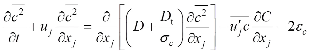
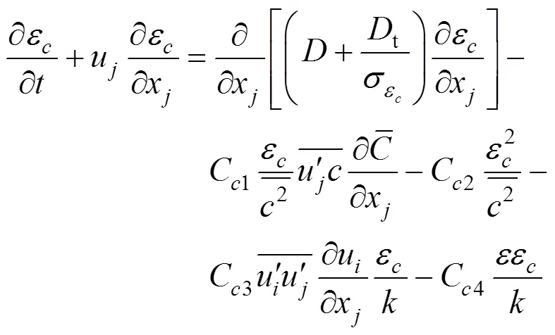
t,C1,C2,C3,C4turbulence model constants for the concentration field
,1,2turbulence model constants for the velocity field
fluctuating concentration (mass fraction)
laminar mass diffusivity coefficient, m2·s-1
tturbulent mass diffusivity coefficient, m2·s-1
momentum source term, N·m-3
vgas flow parameter, m·s-1·(kg·m-3)0.5
LGfriction factor
acceleration of gravity, m·s-2
HETP height of equivalent to a theoretical plate, m
Lliquid holdup
turbulent kinetic energy, m2·s-2
Ggas-phase mass-transfer coefficient, m·s-1
Lliquid-phase mass-transfer coefficient, m·s-1
molecular weight, kg·kmol-1
opoperation pressure, MPa
LGmass transfer rate between the liquid phase and gas phase, kg·s-1·m-3
the side dimension of a corrugation cross section, m
time, s
velocity, m·s-1
Gegas effective velocity, m·s-1
Gsgas superficial velocity, m·s-1
Leliquid effective velocity, m·s-1
Lsliquid superficial velocity, m·s-1
mole fraction in the liquid phase
*interfacial mole fraction in the liquid phase
mole fraction in the gas phase
*interfacial mole fraction in the gas phase
relative volatility
volume fraction of liquid in phase
effective mass diffusivity coefficient, kg·m-1·s-1
contact angle, (°)
mean film thickness, m
energy dissipation rate of turbulence, m2·s-3
turbulent dissipation of the concentration variance, m2·s-3
corrugation angle, (°)
gas-liquid interface curvature, m-1
molecular viscosity, Pa·s
effeffective turbulent viscosity, Pa·s
density, kg·m-3
surface tension, N·m-1

LGfriction force on the gas-liquid interface, N·m-2
Superscripts
spices index
Subscripts
A more volatile component
G gas phase
,coordinate
in inlet
L liquid phase
phase index
1 Hodson, J.S., Fletcher, J.R., Porter K.E., “Fluid mechanical studies of structured distillation packings”,....., Dist. Absorp., (142), 999-1007 (1997).
2 van Gulijk, C., “Using computational fluid dynamics to calculate transversal dispersion in a structured packed bed”,..., 22, S767-S770 (1998).
3 van Baten, J.M., Krishna, R., “Liquid-phase mass transfer within KATAPAK-S®structures studied using computational fluid dynamics simulations”,, 69, 371-377 (2001).
4 van Baten, J.M., Ellenberger, J., Krishna, R., “Radial and axial dispersion of the liquid phase within a KATAPAK-S®structure: experiments. CFD simulations”,..., 56, 813-821 (2001).
5 van Baten, J.M., Krishna, R., “Gas and liquid phase mass transfer within KATAPAK-S®structures studied using CFD simulations”,..., 57, 1531-1536 (2002).
6 Klöker, M., Kenig, E.Y., Gorak, A., “On the development of new column internals for reactive separationsintegration of CFD and process simulation”,, 79 (1-4), 479-485 (2003).
7 Klöker, M., Kenig, E.Y., Piechoia, R., Burghoff, S., Egorov, Y., “CFD-based study on hydrodynamics and mass transfer in fixed catalyst beds”,..., 28 (1), 31-36 (2005).
8 Egorov, Y., Menter, F., Kloker, M., Kenig, E.Y., “On the combination of CFD and rate-based modelling in the simulation of reactive separation processes”,..., 44 (6), 631-644 (2005).
9 Petre, C.F., Larachi, F., Iliuta, I., Grandjean, B.P.A., “Pressure drop through structured packings: breakdown into the contributing mechanisms by CFD modeling”,..., 58, 163-177 (2003).
10 Larachi, F., Petre, C.F., Iliuta, I., Grandjean, B., “Tailoring the pressure drop of structured packings through CFD simulations”,..., 42, 535-541 (2003).
11 Raynal, L., Boyer, C., Ballaguet, J.P., “Liquid holdup and pressure drop determination in structured packing with CFD simulations”,, 82, 871-879 (2004).
12 Zhang, P., “Experimental studies and CFD simulations of fluid flow and mass transfer in a structured packed column at elevated pressure”, Ph.D. Thesis, Tianjin University, Tianjin (2002). (in Chinese)
13 Zhang, P., Liu, C.J., Yuan, X.G., Yu, K.T., “CFD simulations of liquid phase flow in structured packed column”,.... (), 55 (8), 1369-1373 (2004). (in Chinese)
14 Iliuta, I., Larachi, F., “Mechanistic model for structured-packing containing columns: irrigated pressure drop, liquid holdup and packing fractional wetted area”,...., 40, 5140-5146 (2001).
15 Iliuta, I., Petre, C.F., Larachi, F., “Hydrodynamic continuum model for two-phase flow structured-packing-containing columns”,..., 59, 879-888 (2004).
16 Yin, F.H., Sun, C.G., Afacan, A., Nandakumar, K., Chuang, K.T., “CFD modeling of mass-transfer processes in randomly packed distillation columns”,...., 39,1369-1380 (2000).
17 Yin, F., Afacan, A., Nandakumar, K., Chuang, K.T., “Liquid holdup distribution in packed columns: gamma ray tomography and CFD simulation”,..., 41, 473-483 (2002).
18 Jiang, Y., Khadilkar, M.R., Al-Dahhan, M.H., Dudukovic, M.P., “CFD of multiphase flow in packed- bed reactors: 1.-Fluid modeling issues”,., 48 (4), 701-715 (2002).
19 Jiang, Y., Khadilkar, M.R., Al-Dahhan, M.H., Dudukovic, M.P., “CFD of multiphase flow in packed-bed reactors: 2. Results and applications”,., 48 (4), 716-730 (2002).
20 Yuan, Y.H., Han, M.H., Cheng, Y., Wang, D., Jin, Y., “Experimental and CFD analysis of two-phase cross/countercurrent flow in the packed column with a novel internal”,..., 60 (22), 6210-6216 (2005).
21 Szulczewska, B., Zbicinski, I., Gorak, I., “Liquid flow on structured packing: CFD simulation and experimental study”,..., 26 (5), 580-584 (2003).
22 Gu, F., Liu, C.J., Yuan, X.G., Yu K.T., “CFD simulation of liquid film flow on inclined plates”,..., 27 (10), 1099-1104 (2004).
23 Gu, F., “CFD Simulations of the local-flow and mass-transfer in the structured packing”, Ph.D. Thesis, Tianjin University, Tianjin (2004). (in Chinese)
24 Hoffmann, A., Ausner, J., Repke, J.U., Wozny, G., “Fluid dynamics in multiphase distillation processes in packed towers”,..., 29 (6), 1433-1437 (2005).
25 Valluri, P., “Multiphase fluid dynamics in structured packings”, Ph.D. Thesis, Imperial College London, University of London (2004).
26 Valluri, P., Matar, O.K., Hewitt, G.F., Mendes, M.A., “Thin film flow over structured packings at moderate Reynolds numbers”,..., 60, 1965-1975 (2005).
27 Ataki, A., Bart, H.J., “Experimental and CFD simulation study for the wetting of a structured packing element with liquids”,..., 29 (3), 336-347 (2006).
28 Chen, J.B., Tang, Z.L., Wang, G.Q., Liu, C.J., Yuan, X.G., Yu, G.C., “Performance of Mellapak 350Y corrugated sheet structured packing at elevated pressure”,.... (), 55 (2), 335-336 (2004). (in Chinese)
29 Chen, J.B., “Numerical and experimental study of transport phenomena in a structured packed column at high pressure”, Ph.D. Thesis, Tianjin University, Tianjin (2006). (in Chinese)
30 Liu, B.T., “Study of a new mass transfer model of CFD and its application on distillation tray”, Ph.D. Thesis, Tianjin University, Tianjin (2003). (in Chinese)
31 Zhang, Z.S., Turbulence, National Defense Industry Press, Beijing (2002). (in Chinese)
32 Rocha, J.A., Bravo, J.L., Fair, J.R., “Distillation columns containing structured packings: A comprehensive model for their performance. 2. Mass transfer model”,...., 35, 1660-1667 (1996).
33 Gualito, J.J., Cerino, F.J., Cardenas, J.C., Rocha, J.A., “Design method for distillation columns filled with metallic ceramic, or plastic structured packings”,...., 36, 1747-1757 (1997).
34 Fluent Inc., User’s Guide of Fluent 6.0, Lebanon (2001).
2008-10-23,
2009-03-02.
the National Natural Science Foundation of China (20676091), the Program for New Century Excellent Talents in University and the Program for Changjiang Scholars and Innovative Research Teams in Universities (IRT0641).
** To whom correspondence should be addressed. E-mail: yuanxg@tju.edu.cn
猜你喜欢
杂志排行

Chinese Journal of Chemical Engineering的其它文章
- On-line Monitoring for Phosphorus Removal Process and Bacterial Community in Sequencing Batch Reactor*
- Mechanism Study of Rice Straw Pyrolysis by Fourier Transform Infrared Technique*
- Simultaneously Designing and Targeting for Networks with Multiple Resources of Different Qualities*
- Modeling and Control of Nonlinear Discrete-time Systems Based on Compound Neural Networks*
- Effect of Doping Cerium in the Support of Catalyst Pd-Co/Cu-Co-Mn Mixed Oxides on the Oxidative Carbonylation of Phenol
- Biodegradation of Aniline by a Newly Isolated Delftia sp. XYJ6*