Development of an atmospheric fluorocarbon plasma jet generated by pulse modulated microwave discharge
2023-11-19SileCHEN陈思乐XinliuREN任鑫柳ZhaoquanCHEN陈兆权XiaojuanXU徐笑娟TaoCHENG程涛PingLI李平GuanjunZHANG张冠军andXinpeiLU卢新培
Sile CHEN(陈思乐) ,Xinliu REN (任鑫柳) ,Zhaoquan CHEN (陈兆权),* ,Xiaojuan XU(徐笑娟) ,Tao CHENG(程涛) ,Ping LI(李平) ,Guanjun ZHANG(张冠军) and Xinpei LU (卢新培)
1 School of Electrical and Information Engineering,Anhui University of Technology,Ma’anshan 243032,People’s Republic of China
2 School of Electrical and Information Engineering,Anhui University of Science and Technology,Huainan 232001,People’s Republic of China
3 State Key Laboratory of Electrical Insulation and Power Equipment,School of Electrical Engineering,Xi’an Jiaotong University,Xi’an 710049,People’s Republic of China
4 State Key Laboratory of Advanced Electromagnetic Engineering and Technology,Huazhong University of Science and Technology,Wuhan 430074,People’s Republic of China
Abstract Atmospheric fluorocarbon plasma plays an important role in the surface modification of insulating materials like polymers.The existing fluorocarbon plasma is usually generated by dielectric barrier discharge,which has a low concentration of reactive species and may cause insufficient surface fluorination.This work attempts to develop an atmospheric fluorocarbon plasma jet using a coaxial transmission line resonator by microwave discharge with locally enhanced electric field and high density.The gas temperature is reduced by pulse modulation technology.Three kinds of working gases,pure CF4,Ar/CF4 and He/CF4,are utilized to generate the atmospheric microwave fluorocarbon plasma jet.The discharge images,optical emission spectra,electron densities and gas temperatures are studied experimentally.The results show that the Ar/CF4 plasma jet has the best comprehensive performance,such as strong discharge intensity and controllable gas temperature.The electron density of the Ar/CF4 plasma jet has a magnitude of 1020 m-3,indicating a higher density than that of the frequently used dielectric barrier discharge.With the other conditions unchanged,the gas temperature at the end of the Ar/CF4 plasma jet can be reduced from 410.2 to 347.3 K by decreasing the duty cycle of the modulated pulse from 0.5 to 0.1.Thence,the microwave Ar/CF4 plasma jet is considered to be a promising fluorocarbon plasma source for surface fluorination of polymers.
Keywords: microwave discharge,atmospheric pressure plasma jet,fluorocarbon plasma
1.Introduction
Atmospheric pressure fluorocarbon plasma is widely used in the surface fluorination of polymers for the application of hydrophobic surface preparation [1-3] and surface electrical performance improvement [4-6].The polymer surface is modified by the fluorocarbon plasma through various surface processes,like etching,deposition,functionalization,crosslink and so on[7].The surface morphologies and chemical compositions of polymers are changed,leading to changes in surface wettability and flashover strength.
Fluorocarbon plasma is usually generated by the discharge of a fluorocarbon gas such as tetrafluoromethane(CF4).However,it is difficult for the fluorocarbon gas to be ionized at atmospheric pressure due to the strong electron affinity of the fluorine element[8,9].In order to obtain an atmospheric fluorocarbon plasma,a strong electric field is required and the gas temperature accordingly becomes high,leading to the thermal damage of the material surface and the change of reactive species[10].To reduce the breakdown field strength and gas temperature,a large amount of a noble gas,like argon or helium,is usually mixed with the fluorocarbon gas.A noble gas concentration of over 90% is usually required to obtain a fluorocarbon plasma with good electrical performance[6,11-13].
However,with the addition of a large amount of noble gas,the energy is partly consumed by the excitation and ionization of the noble gas.The low concentration of fluorocarbon gas reduces the densities of reactive fluorinecontaining species in plasma,which may further result in insufficient surface fluorination.For example,the typical fluorine content on the material surface treated by atmospheric fluorocarbon plasma is usually 10%-20% [6,7],while it can reach 30%-40% in the case of direct fluorination by fluorine gas [14].Therefore,it is still a challenge to generate an atmospheric fluorocarbon plasma with a high content of fluorine-containing species and low gas temperature.
In recent years,microwave plasma has attracted more and more attention due to its advantages of high density and rich reactive species [15].The local enhancement effect of a microwave electric field makes it easier to ionize the working gas at atmospheric pressure and generate the guided ionization wave [16,17].Thus,the fluorocarbon gas can be ionized efficiently at atmospheric pressure by microwave discharge,and the fluorocarbon plasma with a high content of fluorine-containing species is produced.The gas temperature in microwave fluorocarbon plasma can be controlled by pulse modulation technology combined with the optimization of the operation parameters.For these reasons,the pulse modulated microwave discharge seems to be an ideal method to generate fluorocarbon plasma with excellent performances at atmospheric pressure.
In this work,a pulse modulated microwave power supply is utilized to ignite the discharge in a coaxial transmission line resonator(CTLR).The microwave atmospheric pressure plasma jets (APPJs) in pure CF4,Ar/CF4mixtures and He/CF4mixtures are investigated through the discharge image,optical emission spectrum(OES),electron density and gas temperature.The characteristics of the three types of microwave fluorocarbon plasma are discussed,and the microwave Ar/CF4plasma jet is proposed considering the best overall performances.
2.Experimental setup
2.1.Microwave fluorocarbon plasma jet arrangement
The schematic of the microwave fluorocarbon plasma jet setup is shown in figure 1.The whole experimental setup consists of three parts: the power supply,the discharge device and the working gases system.A homemade pulse modulated microwave source is utilized as the power supply (output power: 0-200 W,microwave frequency: 2.45 GHz,pulse frequency:10 Hz-200 kHz,duty cycle:0.01-0.99),for which the main composition can be found in the [18].All the input microwave powers in this work refer to the peak power.
The discharge device is a copper CTLR which is designed to be a quarter of the wavelength [19].The length of the resonant cavity is 31 mm (excluding the wall thickness of 4 mm) with an outside diameter of 22 mm.One end of the resonator is short circuited and the other end is open circuited,which is indicated in the figure.To obtain a strong electric field near the open end,the inside diameter gradually narrows towards the open end,forming a conical cavity.The maximum inside diameter of the CTLR is 14 mm,while the minimum inside diameter is 6 mm located at the open end.A stainlesssteel needle with a sharpened tip is used as the powered inner electrode.The distance between the tip end of the inner electrode and the open end is about 2 mm.The purpose is also to create a strong electric field at the discharge position.The resonator is connected to the power supply by a sub-miniature version(SMA)connector,which is 3 mm away from the short end of the CTLR.This is the optimized position for the microwave incidence,which makes the position with maximum voltage located at the tip end.Considering the processing errors of the CTLR,the position of the inner electrode tip can be fine-tuned by a knob at the short end.
Three kinds of high purity gases,CF4(99.99%),Ar(99.999%)and He(99.999%),are utilized to form the working gas.The flow rates of working gases are controlled separately by needle valves and mass flow monitors.The gas inlet is set on the side of the resonator.
2.2.Plasma characterization
The discharge image,OES,electron density and gas temperature of microwave fluorocarbon plasma jet are studied in this work.The discharge images in long exposure time(s or ms)are captured by a digital single lens reflex camera(DLSR,Canon EOS 60D),while the discharge images in short exposure time (μs or ns) are taken by an intensified chargecoupled device (ICCD,Andor iStar DH340T).The ICCD camera is triggered by the same pulse signal as that of the 53 dB amplifier.A lens with a focal length ranging from 18 to 135 mm is used for obtaining the discharge images.For comparison,the camera is placed at a fixed distance of 300 mm on the side of the plasma jet during the experiment.
The OES in the range of 200-1000 nm is collected into the spectrometer (Avantes AvaSpec.2048) by a lens and optical fiber.The grating of the spectrometer is 300 lines mm-1,while the width of the slit is 10 μm.The resolution of the spectrometer under this configuration is 0.6-0.7 nm,depending on the starting wavelength of the grating.The acquisition time for the spectrum is selected according to the discharge light intensity.Both the spectra in the port of the CTLR and the end of the APPJs are collected.
The time-varying electron densities of microwave fluorocarbon APPJs are calculated using the microwave Rayleigh scattering method.A home-made device is developed to detect the scattering signals of the APPJs,which is theoretically proportional to the total electron numbers.The time-varying volumes of microwave fluorocarbon APPJs are estimated by a cylinder,which is determined by their ICCD images.The electron density is obtained by dividing the total electron numbers by the plasma volume.Therefore,the timevarying electron density measured in this paper is actually a spatially averaged electron density that changes with time.Detailed information on the method and device can be found in the references,and the measurement error is analysed to be no more than 25% [20,21].
The gas temperatures of microwave fluorocarbon APPJs are measured by a commercial thermometer (Fuzhou Innovation Electronic,IF-C2A3F20).The thermometer consists of a temperature sensitive probe,an optical fiber and a postprocessing module.In different temperatures,the probe can emit the different specific optical signal,which is transmitted by the optical fiber and converted into temperature after processing.The upper limit of temperature measurement is 473.2 K,while the precision is 1 K.Each measurement is repeated three times,and the average value is taken as the result.
3.Results and discussion
3.1.Discharge images
In order to capture the discharge images,the microwave fluorocarbon plasma jets are generated in pure CF4,Ar/CF4and He/CF4respectively.After some pre-experiments,parts of the experimental parameters are selected.The duty cycle of modulated pulse is 0.5,while the frequency is fixed at 20 kHz.The total flow rate of working gases is controlled at 2 l min-1and the CF4concentration is 2% in the case of Ar/CF4and He/CF4plasma jets.For the pure CF4plasma jet,the flow rate is set to be 0.3 l min-1,because the higher flow rate makes the discharge shake and become unstable.
The approximate operating ranges of the three microwave fluorocarbon plasma jets are listed in table 1.It is difficult for the discharge in pure CF4to be ignited directly by the microwave electric field.It is necessary to use a conductor tocontact the tip of the needle electrode for triggering the discharge manually.The ignition of microwave discharge relies on the locally enhanced electric field,which depends on the establishment of a resonance state in the CTLR.However,the resonance conditions are influenced by various factors,like the processing and assembly errors,resulting in deviation from the optimal resonance point.Therefore,significant errors can be observed in the ignition power and minimum sustaining power,especially the ignition power.The pure CF4is able to be ionized under an input power higher than 60-70 W,while the discharge can be maintained until the power is reduced to 38-42 W.After adding the noble gas,the discharge can be ignited without manual assistance.The ignition powers of Ar/CF4and He/CF4are 15-22 W and 6-8 W respectively,while the minimum sustaining powers are 6-8 W and 4-5 W respectively.
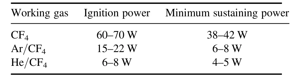
Table 1.Approximate operating ranges of the microwave fluorocarbon plasma jets.
The discharge images of microwave fluorocarbon APPJs are shown in figure 2.In figure 2(a),a ruler is photographed to measure the sizes of the APPJs.The CF4,Ar/CF4and He/CF4plasma jets are shown in figures 2(b)-(d)respectively.All the APPJs present green color and their input power is 120 W.For a clearer view,the exposure times are 100 ms,0.125 ms and 1 ms for the CF4,Ar/CF4and He/CF4plasma jets,while the ISOs are 500,100 and 100 respectively.
A partition structure,which is similar to the flame,is observed in the pure CF4microwave plasma jet.The inner flame with bright light is near the needle tip.It is indicated that the intense excitation and ionization processes occur in the inner flame region.The outer flame is around the inner flame and propagates forward towards the downstream of the gas flow.According to the weak light intensity of the outer flame,the discharge intensity of the outer flame is obviously weaker than that of the inner flame.
The Ar/CF4plasma jet presents a strip shape and the end becomes larger,which is different from the microwave pure Ar plasma jet in the [16,19].The microwave Ar plasma jet gradually becomes sharp when propagating forward,with large amounts of discharge branches.It is considered that the discharge is restrained by the strong electron affinity of CF4.The discharge branches no longer appear in the Ar/CF4plasma jet.The light intensities of Ar/CF4and CF4plasma jets(referring to the inner flame) are similar in the figure,but the exposure time of the former is 8000 times more than that of the latter.It is inferred that the light intensity of the Ar/CF4plasma jet is significantly higher than that of the CF4plasma jet.The light distribution of the Ar/CF4plasma jet along the direction of gas flow is uniform,indicating good transport characteristics.As for He/CF4,the discharge is mainly concentrated inside the CTLR.There is no plasma plume that can be effectively utilized formed outside the device.Therefore,the He/CF4plasma is not considered in the subsequent studies.
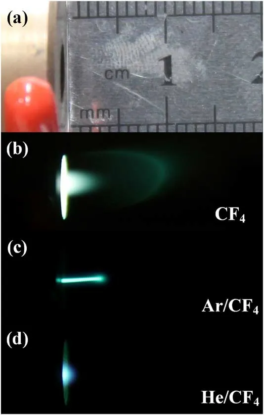
Figure 2.Discharge images of microwave fluorocarbon APPJs.Input power: 120 W.(a)CTLR and ruler;(b) pure CF4,0.3 l min-1,exposure time: 100 ms,ISO: 500;(c) Ar/CF4,2 l min-1,2% CF4,exposure time:0.125 ms,ISO:100;(d)He/CF4,2 l min-1,2% CF4,exposure time: 1 ms,ISO: 100.
Figure 3 shows the lengths of CF4and Ar/CF4plasma jets under different input microwave powers.Both the lengths of the inner flame and the outer flame in the CF4plasma jet are recorded in the figure.With the input power increased from 60 to 160 W,the length of the inner flame is increased from about 1 to 4 mm,while the length of the outer flame is increased from about 4 to 12 mm.The propagation distance of the outer flame with weaker discharge intensity in the CF4plasma jet is longer than that of the inner flame.On the other hand,the length of the Ar/CF4APPJ is at the same level as the inner flame of pure CF4APPJ,but slightly longer than that at the same input power.As the input power increases from 20 to 120 W,the length of Ar/CF4APPJ increases from about 1 to 4 mm.The maximum length of the microwave Ar/CF4APPJ is reached at the input power of 100 W,which is less than that of the microwave Ar APPJ (over 10 mm) in the [16,19].It indirectly reflects that the addition of CF4restrains the development of Ar APPJ.The lengths of the CF4and Ar/CF4plasma jets both increase rapidly at first with the increase of input power,and then the lengths tend to be saturated and may even be slightly shortened.It is related to the complex interaction between the microwave and plasma.
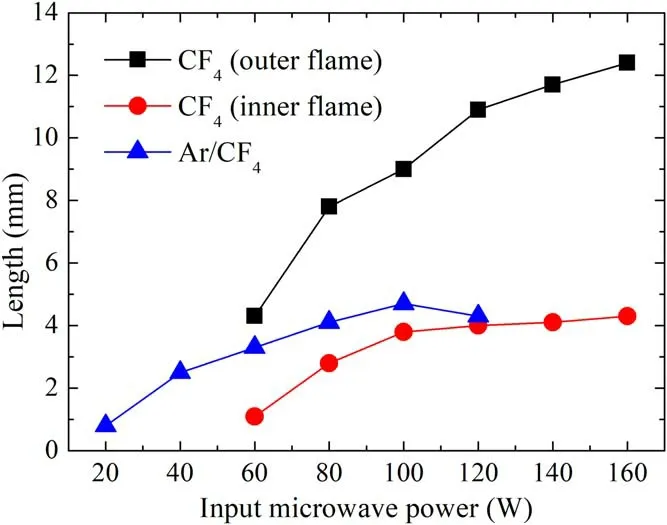
Figure 3.Lengths of microwave CF4 and Ar/CF4 plasma jets versus the input microwave power.
It can also be found that the radii of the CF4and Ar/CF4plasma jets are very different from figure 3.The radius of the CF4plasma jet is relatively large especially for the outer flame,while the radius of the Ar/CF4plasma jet is small.There are two main reasons for the difference.At first,the gas flow rate of the Ar/CF4plasma jet is much higher than that of the CF4plasma jet,which makes the Ar/CF4plasma jet thinner.And then the discharge modes are different in these two gas environments,which is analysed later in the discussion section.
To investigate the ionization processes of the atmospheric microwave fluorocarbon APPJs,the ICCD images of the CF4and Ar/CF4plasma jets in a complete period of modulation pulse are captured.The ICCD is in the kinetics mode with the same trigger signal as the modulation pulse,and the time step for shooting is set to be 0.5 μs.Thus 100 images can be obtained in a period of the 20 kHz modulation pulse,and the typical images are shown in figures 4 and 5.For better visual quality,the exposure time of 50 ns and the input power of 140 W are selected in the case of the CF4plasma jet,while 10 ns and 100 W are selected in the case of the Ar/CF4plasma jet.
The results of the ICCD images are consistent with the camera images in long exposure time.Because the light intensities of the inner flame and outer flame in the microwave CF4plasma jet are very different,the inner flame and outer flame cannot be photographed clearly at the same time.According to the images of the inner flame in figure 4,it is found that the discharge is ignited at about 6.5 μs from the trigger moment since some bright points can be observed in the CTLR port.It is noted that some weak luminescence can be found before 6.5 μs,which is considered background interference.It can be demonstrated with two aspects.At first,the exposure time is relatively long and a large gain is used due to the weak light intensity of CF4plasma,meaning the background interference becomes amplified.The display range of the light intensity in the images is then adjusted for better visual quality.The display upper limit of light intensity is very low,resulting in the amplified background interference being displayed as well.The evidence is that the weak luminescence is not only distributed at the port,but also elsewhere.The discharge intensity increases gradually until the input power disappears at 25 μs (the duty cycle is 0.5 as previously mentioned).Because the ICCD camera has an inherent time delay of about 100 ns,the discharge has already become weak in the image at 25 μs.Subsequently,the discharge is gradually extinguished.The outer flame of the CF4plasma jet is shown in the total image.In order to show the image of the outer flame clearly,the exposure time is set to be 50 μs and the display range of the light intensity is adjusted.The outer flame can be clearly seen in this case,but the inner flame is overexposed.
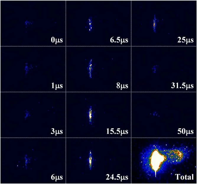
Figure 4.ICCD images of microwave CF4 APPJ.Exposure time:50 ns(50 μs for the total image);input power: 140 W.
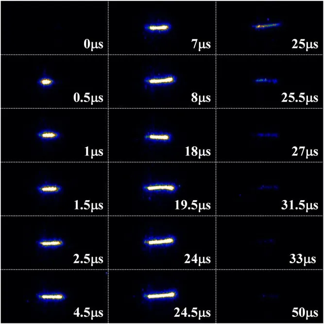
Figure 5.ICCD images of microwave Ar/CF4 APPJ.Exposure time:10 ns;input power: 100 W.
Combining the ICCD and camera images,it is inferred that the ionization mechanisms of the inner flame and outer flame in the CF4plasma jet are very different.The inner flame near the tip is generated by the locally enhanced microwave electric field.However,the mechanism of the outer flame is not clear.The electric field strength at the location of the outer flame is not enough to maintain the discharge.The light intensity of the outer flame increases along the direction of gas flow,which is the direction of electric field strength weakening.Therefore,the outer flame is not generated by the applied electric field.Due to the weak light intensity of the outer flame,the photoionization is also excluded.It is considered that the possible mechanism may be Penning ionization.
For the Ar/CF4plasma jet in figure 5,the discharge is ignited at 0.5 μs,which is earlier than that of the CF4plasma jet.The length of the Ar/CF4plasma jet reaches the level close to the maximum for the first time at 8 μs.Afterwards,the length is slightly shortened and then increased to the maximum again,fluctuating with a certain range(7-24.5 μs).It is indicated that the streamer head is quenched by CF4molecules and then reignited by the electric field of microwave and space charges when it propagates close to the limit position.This process is repeated many times.
The ionization mechanism of the Ar/CF4plasma jet is similar to the microwave pure Ar plasma jet.The discharge initialises near the tip and propagates in the form of a streamer.The ionization enhancement effect can usually be observed in the Ar plasma jet,which occurs at the rising and falling edges of the modulation pulse [19].The rapidly changing electric field increases the electron energy and enhances the ionization,which is shown as the increase of plasma size and light intensity.In the case of the Ar/CF4plasma jet,a large number of electrons are absorbed by CF4molecules due to the strong electron affinity,which weakens the ionization process.The streamer head stops propagating earlier than the Ar plasma jet,shortening the jet length and affecting the formation of the sharp end.The energetic electrons generated at the pulse edge are insufficient to enhance ionization.As a result,no obvious ionization enhancement is found from the ICCD images of the Ar/CF4plasma jet.
3.2.Optical emission spectra
The OES of the microwave CF4and Ar/CF4plasma jets are collected to analyse the composition of the excited reactive species,as shown in figures 6 and 7.In order to explain the distribution of reactive species,both the locations at the CTLR port(location 1)and the end of the plasma jet(location 2)are used to collect the spectra.The discharge is intense at location 1,where the reactive species are usually the most abundant.The OES at location 1 is helpful in the comprehensive understanding of the reactive species.Location 2 is the place where the plasma interacts with the target object in practical applications.The OES at location 2 is beneficial in the understanding of the reactive species actually involved in the surface modification.The lens of the spectrometer is placed perpendicular to the gas flow direction,and the distance between the lens and the plasma jet is 20 mm.
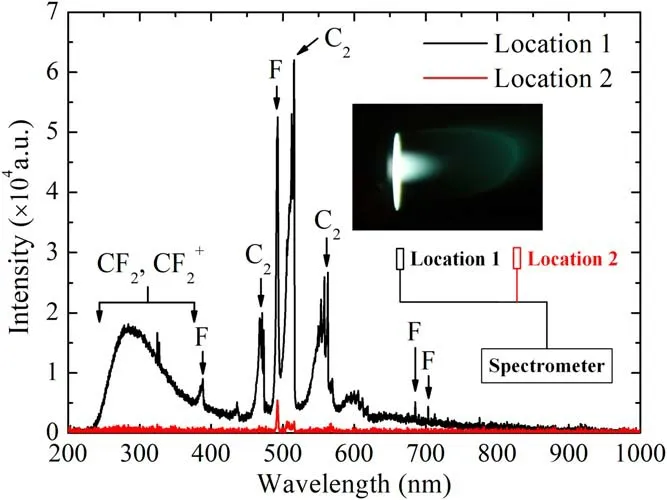
Figure 6.OES of microwave CF4 plasma jets at the CTLR port(location 1) and the APPJ end (location 2).Accumulation time: 2 s;input power: 120 W.
According to [22-27],it can be found that the excited reactive species of the microwave fluorocarbon plasma jet mainly include F atoms,CF2radicals,ions,C2groups and Ar,atoms from the results.A continuous spectrum is located from about 220 to 380 nm,which is originated from the CF2(A1B1-X1A1) radicals and(4b2-6a1) ions.Several F lines at 388.6,493.3,685.6 and 703.7 nm are found in the spectra.The C2groups are formed in the plasma,leading to three emission bands.Among them,the line with the highest intensity is at 516.5 nm (C2: a3Πu-d3Πg(0,0)).The Ar lines are distributed from 700 to 920 nm.Mainly,six Ar lines,706.7,738.4,750.3,763.5,811.5 and 912.3 nm,are observed.
Due to the weak light intensity of the outer flame in CF4APPJ,a longer accumulation time for the spectrometer is needed to capture the spectrum.It is necessary to ensure that the spectrum of the inner flame is not overexposed at the same time in order to compare the spectral characteristics at different locations.Finally,the accumulation time of 2 s and the input power of 120 W are selected,and the results are shown in figure 6.Consistent with the results of discharge images,the overall emission intensity of the inner flame is significantly higher than that of the outer flame.One continuous spectrum originated from CF2groups,three bands responsible for C2groups and several F lines are observed in the spectrum of the inner flame.However,only one band of C2and one F line can be found in the spectrum of the outer flame.This means that the densities of the reactive species are low in the end of the outer flame.There is no effective transport of the reactive species between the inner and outer flame of the CF4plasma jet,which is disadvantageous for the surface modification of materials.
The spectra collected under the conditions where the input power is 60 W and accumulation time is 5 ms are shown in figure 7.Compared with those of CF4APPJ,the spectra of Ar/CF4APPJ show equal light intensity,but are only collected at half of the input power and 1/400th of the accumulation time.It also means that the overall light intensity of the Ar/CF4plasma jet is much stronger than that of the CF4plasma jet.The Ar/CF4APPJ also contains the CF2and C2groups from the spectra(the continuous spectrum and the three bands).However,the number of F lines decreases and several Ar lines are observed.It is noted that the emission intensities in the CTLR port and the end of the Ar/CF4plasma jet are similar.There is only a small attenuation of the spectral intensity during the discharge propagation,which indicates the high density of the reactive species in the end of the Ar/CF4plasma jet.From this point of view,the Ar/CF4plasma jet is of more benefit to the surface treatment applications than to the CF4plasma jet.
3.3.Electron densities
The electron densities of microwave fluorocarbon APPJs are measured to illustrate the high densities of microwave plasma.The transient ICCD images of the outer flame in the CF4plasma jet are hard to obtain due to its weak light intensity.Therefore,the transient volume of the CF4plasma jet corresponding to the scattering signal cannot be estimated,making the time varying electron density of the CF4plasma jet unavailable.In the case of the Ar/CF4plasma jet,the time varying length,radius and electron density are obtained by the ICCD images with an exposure time of 10 ns,which are shown in figures 8 and 9.
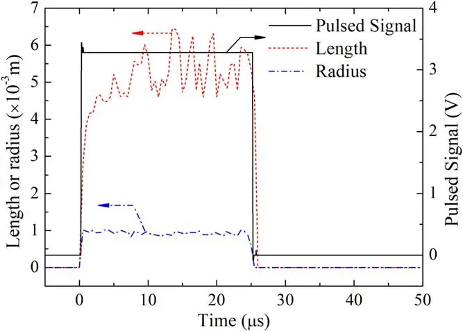
Figure 8.The time-varying length and radius of microwave Ar/CF4 APPJ measured by ICCD images.Input power: 120 W.
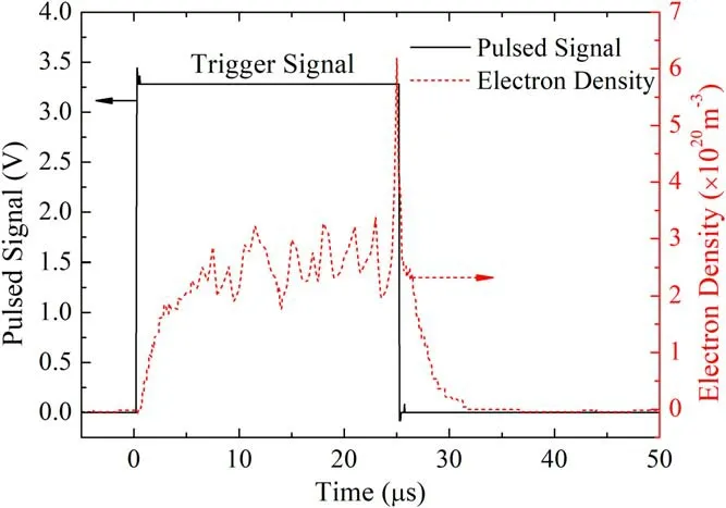
Figure 9.The time-varying electron density of microwave Ar/CF4 APPJ.Input power: 120 W.
According to the shapes of Ar/CF4plasma jets,an equivalent cylinder is used to estimate the volumes.A ruler is also photographed by ICCD to measure the equivalent lengths and radii of Ar/CF4APPJs at different moments in a complete pulse modulation period.The real distance corresponding to each pixel point(denoted by dp)is calculated based on dividing the real distance on the ruler by the corresponding number of pixel points in the image.The size of the plasma jet can be obtained by multiplying the number of pixel points by dpfrom the ICCD image.To reduce the error,the image brightness is increased and the outer edge is selected as the benchmark during the measurement.For the length,the maximum number of pixel points at both ends of the plasma is used.For the radius,the numbers of pixel points at the front,middle and back of the plasma are measured respectively,and the average number is taken into account.The equivalent lengths of Ar/CF4APPJs vary within a certain range after increasing to about 5 mm with time.The equivalent radii of Ar/CF4APPJs are constant at around 1 mm.When the input power disappears,the equivalent length and radius decrease to 0 within several microseconds.Within 0-27 μs,the data in figure 8 are the actual measurement results by ICCD images.At other times,the plasma jets are hard to capture because of the weak light intensities.The lengths and radii are set to be a constant instead of 0.Moreover,the scattering signal is usually not 0 due to the background noise.Therefore,the imaginary lengths and radii are set to prevent numerical divergence,and the data are fitted by a self-made program in the calculation of electron density.
The total electron numbers are obtained from the scattered signal,which can be calculated by the in-phase signal UIand orthogonal signal UQfrom the device.The original data of the UIand UQare given in the supplementary material.The calculation results of electron density versus time are shown in figure 9,and the trigger signal of the modulation pulse is also displayed.The electron density of the Ar/CF4plasma jet increases rapidly at first,and then reaches 2.5×10²⁰m-3and varies within a certain range.The trend originated from that of the equivalent length.At the falling edge of the modulation pulse,the electron density suddenly increases and reaches a maximum of 4.8×10²⁰m-3at 26.5 μs.When the input power disappears,the electron density decreases to 0 within several microseconds.It is inferred that the ionization enhancement still occurs from the electron density at the falling edge.The ionization enhancement is not obvious in the ICCD images because it is weakened by the electron affinity of CF4.Overall,the electron densities of microwave Ar/CF4APPJs have a magnitude of 1020m-3,which is close to the results of(5-8) × 1020m-3in an atmospheric microwave Ar plasma torch [28].Compared with the reported electron density of 1017m-3in dielectric barrier discharge [11,29],the electron density of microwave plasma is significantly higher.
3.4.Gas temperatures
To prevent the thermal damage of the objects,gas temperature is an important parameter for the plasma treatment.In this work,there is an attempt to evaluate the gas temperatures of the CF4and Ar/CF4plasma jets,using an optical fiber thermometer.However,the gas temperature of the CF4plasma jet exceeds the range of the optical fiber thermometer.In order to estimate the gas temperature of the CF4plasma jet,solder wire,with a high melting point of about 603.2-623.2 K,is used to contact the APPJ.Even the outer flame of the CF4APPJ can melt the solder wire in several seconds.It can be inferred that the gas temperature in the outer flame of the CF4plasma jet is at least higher than 603.2 K,and the gas temperature of the inner flame may be even higher.
The gas temperature at the end of the Ar/CF4plasma jet is measured and shown in figure 10.The gas temperature rises rapidly at first and then tends to rise gradually with the increase of input power.When the input power is from 20 to 120 W,the gas temperature rises from about 364.4 to 428.8 K.The gas temperature of the Ar/CF4plasma jet is much lower than that of the CF4plasma jet,which is related to the addition of Ar and the higher gas flow rate.Nevertheless,the gas temperatures of the proposed Ar/CF4APPJ is still too high for some common insulating materials,such as crosslinked polyethylene,epoxy resin,polymethyl methacrylate and so on.
It is necessary to further reduce the gas temperature to obtain a wider range of applications.The operation parameters,like the input microwave power,the gas flow rate and so on,combined with the pulse modulation technology,are necessary to be taken into account.The gas temperatures of the Ar/CF4plasma jet in different duty cycles and gas flow rates are listed in table 2.The gas flow rate is fixed at 2 l min-1when the duty cycle is changed.The duty cycle is fixed at 0.5 when the gas flow rate is changed.In the measurement,the input microwave power is 60 W,while the concentration of CF4is 2%.From the result,it can be found that the higher gas flow rate and lower duty cycle are helpful in reducing the gas temperature.Thus,the gas temperature of the Ar/CF4plasma jet can be controlled in a relatively wide range.
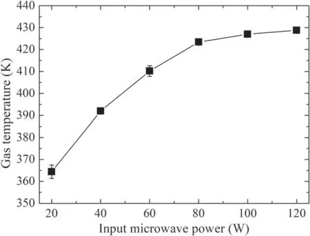
Figure 10.Gas temperatures of microwave Ar/CF4 plasma jets versus the input microwave power.
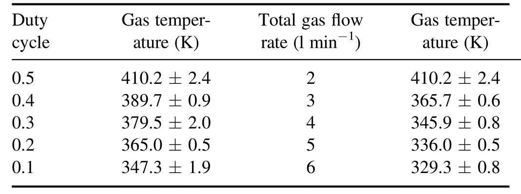
Table 2.Gas temperatures of Ar/CF4 plasma jet in different duty cycles and gas flow rates.The flow rate of working gases is constant at 2 l min-1 when the duty cycle is changed.The duty cycle is fixed at 0.5 when the flow rate of working gases is changed.Input power:60 W;CF4 volume fraction: 2%.
3.5.Discussion
3.5.1.Pulse modulated microwave discharge.The local enhancement effect is an important feature of microwave electric field,which is originated from the interaction between the microwave and the metal electrodes.In CTLR,the generation of locally enhanced electric field can be explained by the theory of surface plasmon polaritons (SPPs) [30].The input microwave propagates along the surface of the inner electrode.The interaction between microwave and the inner electrode forms the surface waves of SPPs around the inner electrode.The SPPs undergo reflection and resonance to form a standing wave,which maximizes the voltage at the tip end of the inner electrode.The electric field at the tip end is enhanced locally and ignites the discharge.The plasma generated by this way usually has a high density,which makes the plasma frequency higher than the microwave frequency.The microwave cannot enter the plasma and continues to propagate along the plasma surface in the form of SPPs.The electric field around the plasma plume is enhanced,driving the plasma propagating forward.However,the applied electric field is only enhanced locally,which is sharply decreased outside the CTLR with the distance.The electric field of the SPPs varies at different locations due to their characteristic wavelength.When the plasma propagates to a location with weak electric field (such as a wave node),its length tends to approach the maximum.In this case,a higher input power is also difficult to effectively enhance the electric field.The length may not necessarily continue to increase unless the input power increases significantly.The pulse modulation technology actually reduces the gas temperature by reducing the input power.However,the ionization enhancement occurs due to the fast-changing electric field at the rising and falling edges of modulated pulse.It means that the ionization efficiency of pulse modulated microwave discharge is higher than that of continuous microwave discharge under the same discharge power.Besides,pulse modulation can be used as an additional regulation method of plasma parameters,which is helpful in obtaining plasma with high density and low temperature.
3.5.2.Atmospheric microwave CF4plasma jet.The CF4has a high breakdown field strength at atmospheric pressure,which is difficult to ionize using dielectric barrier discharge excited by the medium frequency AC high voltage.Due to the local enhancement effect,the microwave electric field is able to ionize CF4molecules and form an atmospheric plasma jet.However,the strong electron affinity of CF4makes it easy to adsorb electrons,restraining the propagation of discharge.As a result,the discharge is concentrated near the inner electrode and the port of CTLR and presents a diffuse mode with a large radius,forming the inner flame.The electric field strength outside the port significantly decreases with the distance.When the electric field strength cannot maintain the ionization,the inner flame is extinguished and the light intensity is significantly weakened.However,the light intensity of the outer flame,which is around the inner flame,increases along the downstream direction of gas flow.Therefore,a dark area is formed between the outer flame and the inner flame.It is considered that the outer flame is generated by the Penning ionization due to three reasons.At first,the other possible processes like electric field ionization or photoionization are excluded.And then,the excited CF4molecules with relatively high energy (12.85 eV) can be generated in the CF4discharge,of which energy is higher than the energy threshold of the most excitation reactions of N2and O2,and the ionization of O2(12.06 eV) according to the database [31].The ionization generated by this way may be relatively weak,which is consistent with the results of the discharge images and OES.Finally,the light intensity of the outer flame increases along the downstream direction of the gas flow.It is consistent with the direction where the concentration of air impurities increases.Because the outer flame is induced by the energetic neutral particles,the diffusion of energetic neutral particles makes the radius of the outer flame larger.Except for the weak discharge intensity,the gas temperatures of CF4APPJs are also too high for surface treatment of materials.Therefore,the current microwave CF4plasma jet is not suitable for practical applications.
3.5.3.Atmospheric microwave He/CF4plasma jet.The microwave He/CF4discharge is concentrated inside the CTLR.There is no effective plasma jet formed outside the device.In the medium frequency dielectric barrier discharge,the He discharge usually propagates towards the high-voltage side.It is also difficult to generate long plasma jets towards the ground electrode outside the device.To increase the length of the He/CF4plasma jet,the powered electrode is usually set in downstream of the gas flow in the case of dielectric barrier discharge[12].The reason why He/CF4cannot form a plasma jet is originated from the discharge characteristics of He.The He discharge usually presents a glow mode,mainly driven by the applied electric field.The electric field strength outside the CTLR is insufficient to maintain the He/CF4discharge.Therefore,the working gases of He/CF4mixtures are difficult to be used in the microwave discharge device of this work.A discharge structure specially designed for the characteristics of helium discharge is needed.
3.5.4.Atmospheric microwave Ar/CF4plasma jet.The Ar/CF4APPJ in this work has the best overall performance.The Ar/CF4plasma jet is formed outside the CTLR by the strong electric field of the space charges in the streamer head.However,the electric field of the space charges is nonuniform,resulting in the small radius of the Ar/CF4plasma jet.The discharge intensity of the Ar/CF4plasma jet is stronger than that of the CF4plasma jet,and the density of the reactive species hardly attenuates at the end of the APPJ.The electron density of the Ar/CF4APPJ is much higher than that of the dielectric barrier glow discharge,which is often utilized in the surface treatment of materials.It is indicated that the content of the reactive fluorocarbon groups in the Ar/CF4plasma jet is also higher.On the one hand,electron collision is the main approach of CF4ionization.On the other hand,the bands of C2groups are observed in the OES.The C2groups are the products of stepwise ionization of CF4,which are hard to observe in the fluorocarbon plasma generated by dielectric barrier discharge [12].The CF4molecules are ionized more thoroughly,indicating more production of fluorocarbon groups.Compared with the CF4APPJ,the Ar/CF4APPJ has lower gas temperatures.The gas temperatures can be further decreased by optimizing the experimental conditions combined with the pulse modulation technology.It should be noted that reducing the gas temperature should not unduly affect the other characteristics of the plasma jet.A comprehensive control strategy will be further studied in the future.To sum up,the Ar/CF4plasma jet is the most promising microwave fluorocarbon plasma source for the surface treatment of insulating materials.
4.Conclusions
In this work,atmospheric microwave fluorocarbon plasma jets are developed using three working gases of pure CF4,Ar/CF4and He/CF4.The discharge images,the OES,the electron densities and the gas temperatures of the microwave fluorocarbon plasmas are studied experimentally.The main conclusions are as follows.
(1) The atmospheric microwave fluorocarbon plasma jets can be generated in the working gases of CF4and Ar/CF4.However,the microwave plasma generated by He/CF4discharge is mainly concentrated inside the CTLR.A plasma jet outside the CTLR is difficult to form in He/CF4.
(2) The microwave electric field is able to ionize the pure CF4at atmospheric pressure and form a plasma jet.The CF4plasma jet is divided into the inner flame and the outer flame.The discharge intensity of the inner flame is much stronger than that of the outer flame,and the reactive species cannot be effectively transported to the outer flame.The gas temperatures of the CF4APPJ are too high for surface fluorination of polymers.
(3) The excited reactive species in the end of the Ar/CF4plasma jet are close to those of the CTLR port.The electron density of the Ar/CF4plasma jet reaches 1020m-3,indicating a high concentration of fluorocarbon groups.The gas temperature at the end of the Ar/CF4plasma jet rises from 364.4 to 428.8 K with the increase of input power from 20 to 120 W.It can be further reduced by decreasing the duty cycle and increasing the flow rate of working gases.Compared with the CF4APPJ,the discharge intensity of the Ar/CF4plasma jet is stronger and the gas temperature of the Ar/CF4plasma jet is even lower.In summary,it is a promising method for generating an atmospheric microwave fluorocarbon plasma jet with higher density and lower gas temperature using Ar/CF4,which has prospects in the surface fluorination of polymers.
Acknowledgments
This work is partly supported by National Natural Science Foundation of China (Nos.52207147 and 52177126),the Anhui Provincial Natural Science Foundation (Nos.2208085QE168 and 2108085ME180) and the Anhui Provincial Natural Science Research Project of Higher Education(No.2022AH050301).
Supplementary material
The original data of the in-phase signal UIand orthogonal signal UQof the microwave Ar/CF4plasma jet proposed in this paper are listed in the supplementary material.The total microwave Rayleigh scattering signal can be obtained by these two signals.The detailed calculation method and process can be found in the reference as mentioned in the text.
猜你喜欢
杂志排行

Plasma Science and Technology的其它文章
- Preparation of highly efficient antibacterial non-woven by facile plasma-induced graft polymerizing of DADMAC
- Multiple chemical warfare agent simulant decontamination by self-driven microplasma
- Wet flashover voltage improvement of the ceramics with dielectric barrier discharge
- Experimental and numerical investigation on the uniformity of nanosecond pulsed dielectric barrier discharge influenced by pulse parameters
- Investigation of phase modulation and propagation-route effect from unmatched large-scale structures for Doppler reflectometry measurement through 2D full-wave modeling
- SOLPS-ITER drift modeling of neon impurity seeded plasmas in EAST with favorable and unfavorable toroidal magnetic field direction