Research on arc root stagnation when small current is interrupted in self-excited circuit breaker
2022-11-17ShidongPENG彭世东JingLI李静YundongCAO曹云东ChongyangHUANG黄翀阳andShuxinLIU刘树鑫
Shidong PENG(彭世东),Jing LI(李静),Yundong CAO(曹云东),Chongyang HUANG(黄翀阳)and Shuxin LIU(刘树鑫)
Key Lab of Special Electric Machine and High Voltage Apparatus(College of Electrical Engineering,Shenyang University of Technology),Shenyang 110870,People’s Republic of China
Abstract The self-excited DC air circuit breaker(SE-DCCB)has been widely used in urban rail transit due to its excellent stability.It can realize forward and reverse interruption,but has difficulty interrupting small currents due to the phenomenon of arc root sticking at the entrance of the arc chamber in the splitting process,which is known as arc root stagnation.A coupling model of the self-excited magnetic field and magnetohydrodynamics is established for the SE-DCCB with the traditional structure.The magnetic field,temperature and airflow distribution in the arc chamber are investigated with an interrupting current of 150 A.The simulation results show that the direction and magnitude of the magnetic blowout force are the dominant factors in the arc root stagnation.The local high temperature of the arc chamber due to arc root stagnation increases the obstruction effect of the airflow vortex on the arc root movement,which significantly increases the arc duration time of small current interruption.Based on the research,the structure of the magnetic conductance plate of the actual product is improved,which can improve the direction and magnitude of the magnetic blowout force at the arc root so as to restrain the development of the airflow vortex effectively and solve the problem of arc root stagnation when the small current is interrupted.The simulation results show that the circuit breaker with improved structure has a better performance for a small current interruption range from 100 A to 350 A.
Keywords:self-excited DC air circuit breaker,small current interruption,magnetic blowout force,arc root stagnation,airflow vortex
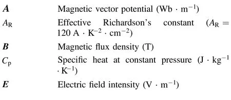
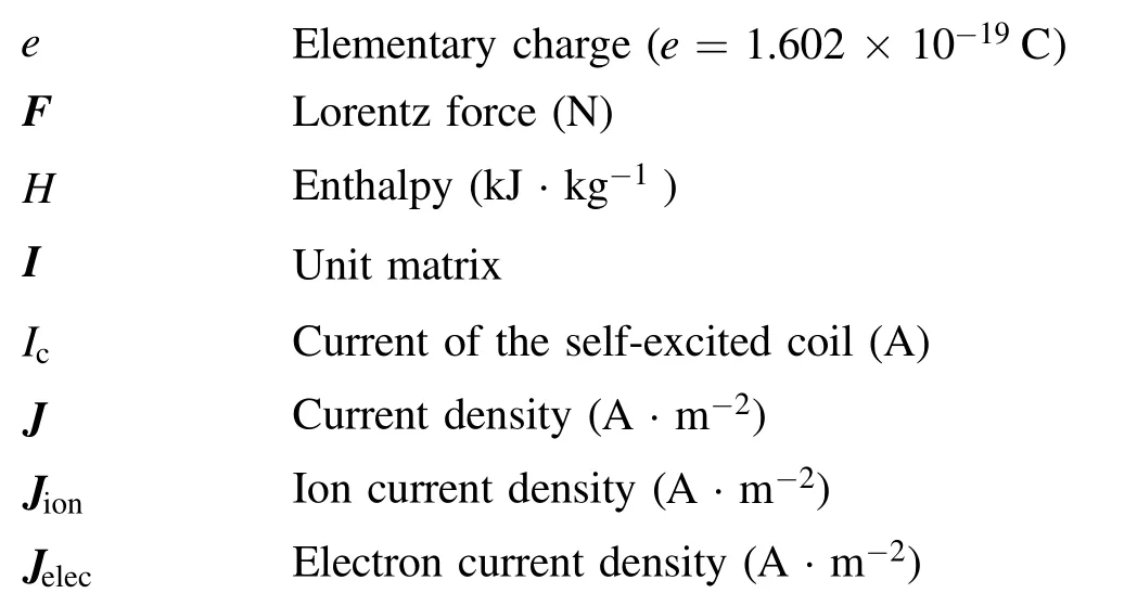
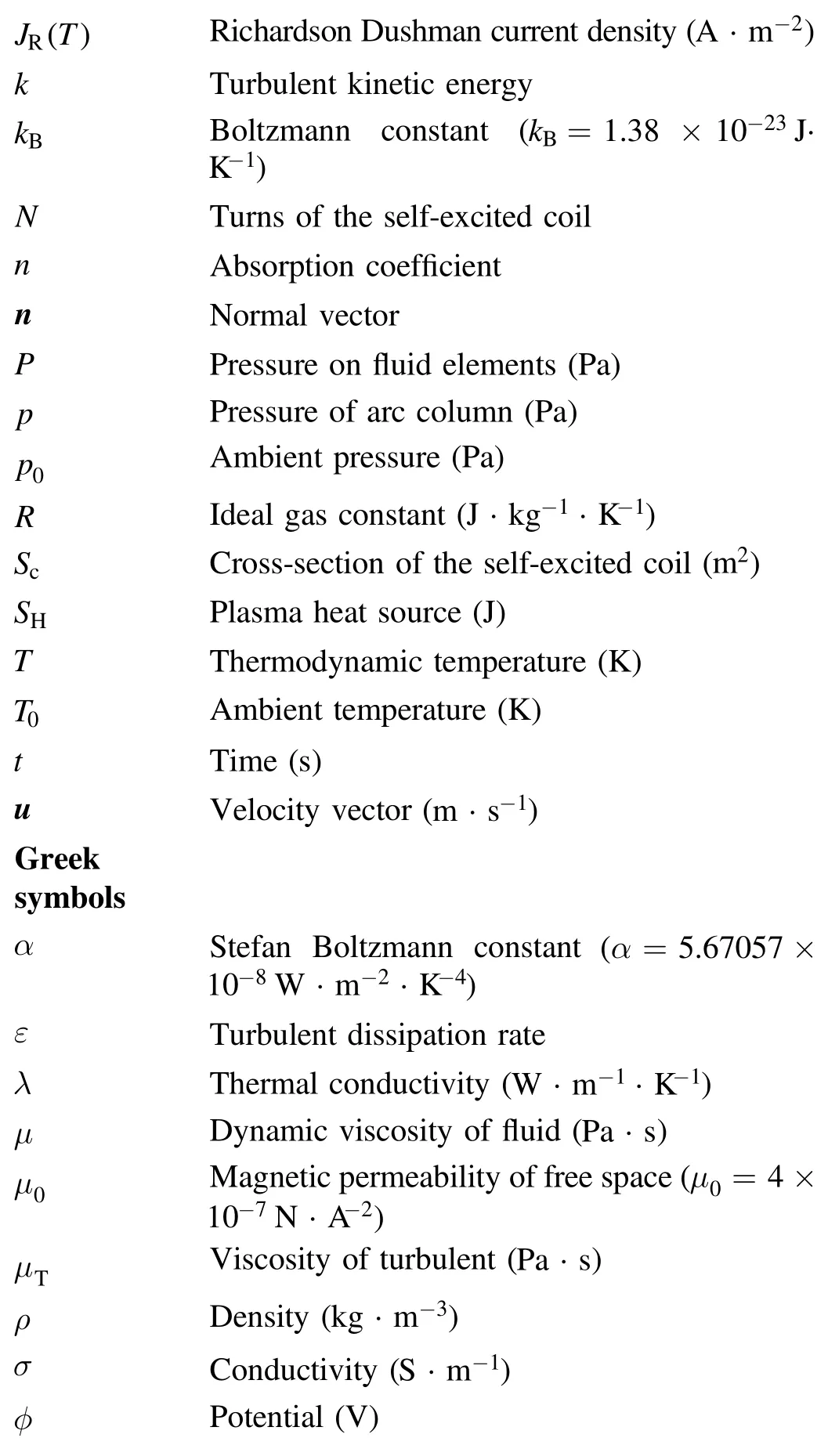
Nomenclature
1.Introduction
Large-capacity self-excited DC air circuit breakers(SE-DCCBs)have excellent stability and are often used in urban rail transit,ship propulsion and other industries that require high stability[1].In this type of circuit breaker,the external magnetic blowout component is usually used to drive the arc into the arc chamber,and then the arc is cut by the splitter plates.In the field of rail transit protection,in order to interrupt the current from or feedback to the catenary when the train works,the self-excited arc blowout component is adopted.In this component,when the contacts of the circuit breaker separate,the self-excited coil is connected with the arc in series,and the arc current is injected into the self-excited coil,which can produce a self-excited magnetic field.When the current reverses,the self-excited magnetic field in the arc chamber also reverses;thus,bi-directional interrupting is possible,which is called non-polarity interrupting[2,3].
The SE-DCCB for rail transit can be divided into two types:one is used on land and the other is used on vehicles.The interrupting class of circuit breaker used on land has reached 1800 V/4000 A,and that used on vehicles has reached 1800 V/1500 A.When the interrupting current approaches the rated current of the SE-DCCB,the arc can get sufficient magnetic blowout force from the self-excited coil and interrupt successfully,while when the working current is much less than the rated current,which often happens in train operation,the current injected into the coil is low,and the arc cannot get sufficient magnetic blowout force,which leads to interruption failure.Increasing the turns of the coil or adding an air blast device seems to resolve the problem of small current interruption faced in SE-DCCB,but increasing the turns will increase the volume of the SE-DCCB,and when adding the air blast device it is difficult to ensure the stability of the device.Optimization of magnetic field distribution and thus improving the arc motion characteristics in SE-DCCB is a feasible method to improve the ability of small current interruption.Most of the existing investigations on interrupting small current are aimed at SF6circuit breakers[4,5],vacuum circuit breakers[6,7]and hybrid circuit breakers[8].The problem with these breakers is the overvoltage generated when the small current is chopped,which can easily lead to restriking.In SE-DCCB,the magnetic field of the coil is taken from the arc current,so when the small current is interrupted,the arc cannot get enough magnetic blowout force to quench it.But at present,there is little research on the small current interruption phenomenon of SE-DCCB.In previous investigations,research on air circuit breakers was based on experimental and theoretical analysis.Researchers usually focused on the stagnation phenomenon at arc formation stage[9,10]and the arc root commutation from the contact to the arc runner[11-14],which only lasts for a few milliseconds.In recent years,with the increase of interrupting voltage and current levels,the arc duration time has become longer,especially when the small current is interrupted in SE-DCCB,whose arc duration time increases to hundreds of milliseconds.Compared with this,the stagnation time of the arc initial stage can be ignored.Therefore,this paper mainly focuses on the stagnation phenomenon of arc root sticking at the arc runner during arc combustion.In studies of the air circuit breaker,more attention has been paid to the later stages of the arc movement[15,16].In the literature[17,18],a simplified arc chamber model was developed to simulate the arc motion,and the mechanism of interaction between the airflow field and the arc motion was derived,where it was considered that the high temperature at the arc root distorted the flow field and affected the arc motion.The high-temperature gas at the arc root gathering at the entrance of the arc chamber can also cause restrike[19].In addition,special phenomena of the arc while entering the arc chamber have also received more and more attention,including the stagnation of the arc root at the entrance of the arc chamber[20],reverse motion of the arc between the splitter plates[21],double airflow vortexes at the arc root[22],and the double arc root phenomenon when the arc is cut by the splitter plates[23],which have an important influence on the arc duration time.The study of the interaction mechanism between the magnetic field and the arc helps to explain the special phenomenon of the arc over the physical view and provide theoretical foundation for the expansion and improvement of the interrupting capacity of the circuit breaker.McBrideet alinvestigated the law of arc root jumping from the contact to the arc runner under the action of the magnetic field[11-13].Schlitzet alestablished a 3D model to study the influence of the self-excited magnetic field of the arc and the external magnetic field on the arc motion,considering gas generation from the gas exhausted material[24,25].Leeet alsimulated the magnetic field of 1.5 kV quickbreak air circuit breaker,trying to find an effective method to improve the magnetic flux density in the arc chamber[26].Huanget alstudied the influence of contact opening speed on the interrupting characteristics under the condition of the magnetic field[27].The motion characteristics of the arc in SEDCCB cannot be reflected veritably if the coupling relationship between the self-excited magnetic field and magnetohydrodynamics(MHD)model is not considered in the investigation.Establishing a coupling model to investigate the characteristics of small current interruption in SE-DCCB has practical application value.
The MHD model is the most widely used model in arc simulation,and requires elaborate mesh division because of the complex multi-physical coupling relationship,which leads to a large number of meshes in the numerical model.The arc duration time of small current interruption is long,so the simulation needs a large amount of computing resources.Most of the previous investigations focus on the interruption characteristics of large current,but few studies focus on small current.The complex coupling relationship between the MHD model and the self-excited magnetic field exists in the SEDCCB,which makes modeling difficult.Most of the existing models simplify the coupling relationship and apply uniform magnetic flux density to the arc chamber[28-30].The coil current of the SE-DCCB is injected by the arc current,and the time-varying process of the arc current will affect the magnetic field distribution in the arc chamber[31].References[32-35]investigated the coupling calculation of the arc and magnetic field,which is mainly focused on the external magnetic field created by the conductor and the MHD model.However,the SE-DCCB generates a self-excited magnetic field through the arc current,which is superimposed on the external magnetic field,and acting together on the arc to drive the arc movement,so the coupling relationship between the magnetic field and the arc is more complex.This work considers not only the external magnetic field generated by the conductor,but also the timevarying magnetic field generated by the blowout coil,which varies with the arc current,and the arc current is fed back to the blowout coil as coil excitation in real time during the simulation.The difficulty in interrupting small current in the SEDCCB is due to the insufficient magnetic blowout force.This work considers both the external magnetic field generated by the conductor and the self-excited magnetic field generated by the blowout coil,and realizes real-time coupling with the MHD model,which can effectively predict the arc behavior when small current is interrupted in the SE-DCCB.
Therefore,based on the above method,the research in this paper mainly consists of the following parts.In section 3.1,the characteristics of small current interruption in the traditional structure are investigated.In section 3.2,an improved structure based on simulation and theoretical analysis is proposed.In section 3.3,the characteristics of small current interruption in the improved structure were compared with that in the traditional one.In section 3.4,the arc root stagnation phenomenon and double airflow vortexes when small current is interrupted in SE-DCCB were investigated.In section 3.5,the arc characteristics when interrupting different current levels in the improved structure were investigated.This investigation provides a feasible numerical simulation method for product R&D,and meanwhile provides theoretical guidance for product design and development.
2.Establishment of model
2.1.Geometric model
According to the actual product,the geometric model of the SE-DCCB with the traditional structure is shown in figure 1(a),The arc chamber is composed of upper and lower magnetic conductance plates,upper and lower magnetic connections,coils and iron cores.The length(xdirection),width(ydirection)and height(zdirection)of the arc chamber are 568 mm,470 mm and 100 mm,respectively,including 60 splitter plates.The electrode separation is 34 mm.The length,width and thickness of the splitter plates are 280 mm,100 mm and 2.5 mm,respectively,and the separation of the splitter plates is 6.5 mm.The magnetic conductance plates and magnetic connections are made of steel with a permeability of 6000 N ·m-2.In the model,there is a circular air outlet whose diameter is 20 mm on both sides of the arc runner[36,37].Figure 1(b)is a simplified model of the middle cross-sectional view of the arc chamber,and the splitter plates and arc runner are made of copper.
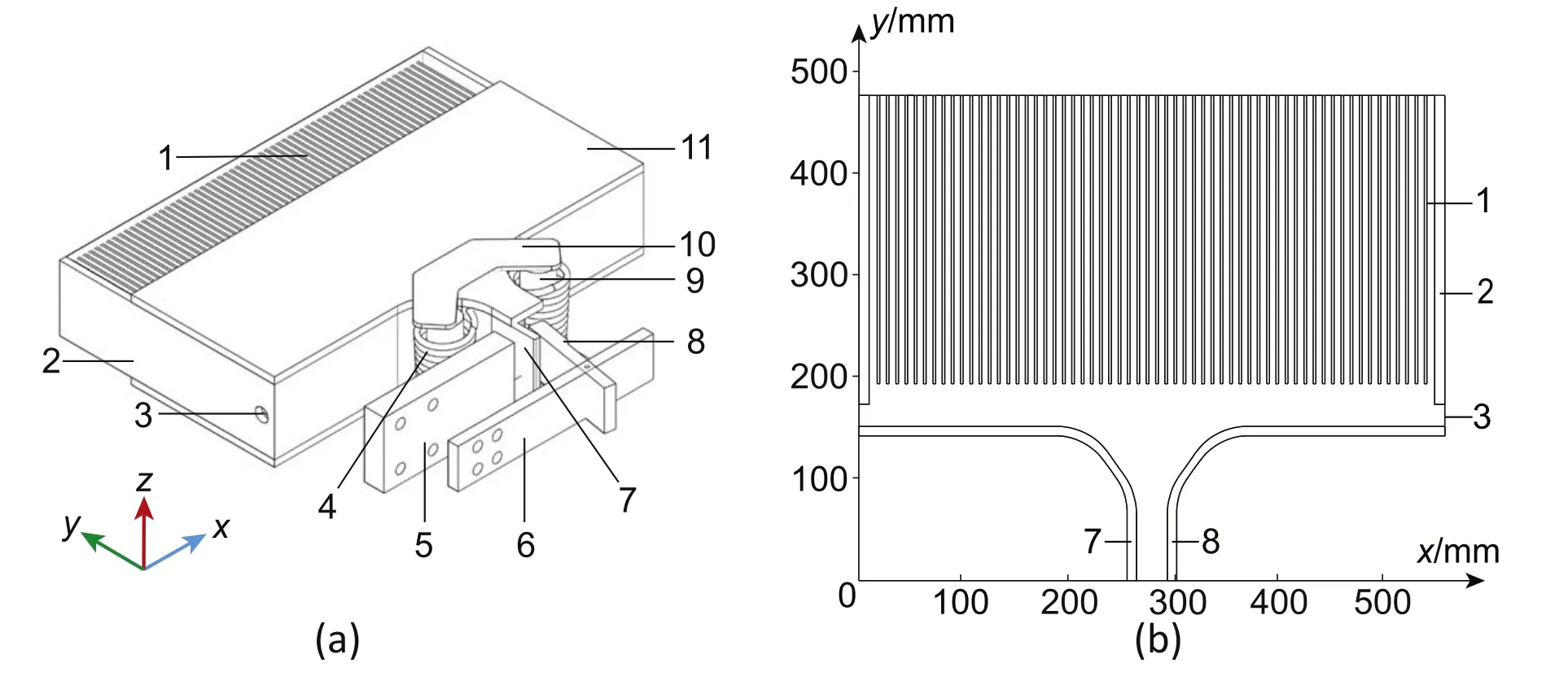
Figure 1.Geometric model of SE-DCCB.(a)Arc chamber with traditional structure,(b)middle cross-sectional view of the arc chamber,1-Splitter plate,2-Arc runner,3-Side air outlet,4-Coil,5-Upper busbar,6-Lower busbar,7-Fixed contact,8-Moving contact,9-Iron core,10-Magnetic conductance connection,11-Integral magnetic conductance plate.
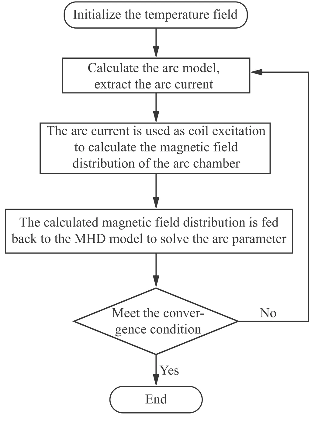
Figure 2.Flowchart of coupling MHD model and self-excited magnetic field.
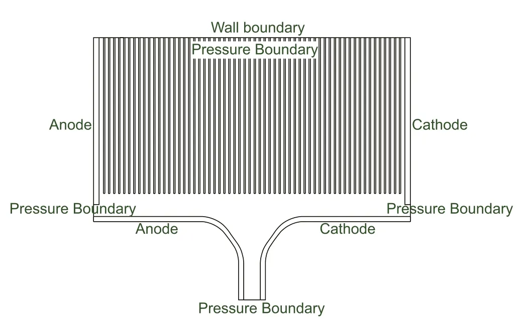
Figure 3.Schematic diagram of boundary condition setting in the model.
2.2.Assumptions
The arc-splitting process of the SE-DCCB involves complex coupling relations between multi-physical fields[38].Therefore,the assumptions should be adopted to reduce the calculation quantity and achieve better convergence within the allowable error range.In this investigation,the arc duration time of the SE-DCCB is greater than 100 ms when interrupting the small current,and the contact usually stops moving when it reaches maximum electrode separation within 10 ms.This study focuses on the dynamic characteristics of the arc from moving along the arc runner to extinguishing.Therefore,the early behavior of the arc,which is related to the contact opening speed and metal bridge,has little effect on the later behavior.The arc energy is low when the small current is interrupted,and so is the arc temperature.For a large arc chamber size,the ablations of contacts and arc runners are not significant;therefore,less metal vapor is produced during arc combustion.Based on the above reasons and previous investigations,which have been proved to ensure the accuracy of calculation[16,28,34],the following hypotheses are proposed in this work.
(1)It is assumed that the arc has been generated between two contacts with fixed distance without considering its opening process.
(2)The influence of erosion caused by the arc is not considered[39,40].
(3)The arc plasma fluid is locally neutral Newtonian fluid and incompressible turbulence flow[41,42].
(4)The effect of metal vapor is ignored here[41].
(5)The arc column has complete ionization[41],and its physical property parameters are only the function of temperature and air pressure[3,28].
2.3.Governing equations and boundary conditions
The MHD model,which describes the arc plasma fluid motion,and the Maxwell equation,which is used to solve the electromagnetic field distribution,are the basic governing equations in this model.The equations are described below.
The magnetic field control equations to calculate the magnetic field distribution in the arc chamber are as follows:
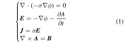
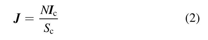
The coil excitation is given by the following equation:
The MHD model,including governing equations of fluid and electromagnetic field equations,is as shown in equations(1)and(3)-(13).
Mass conservation equation:
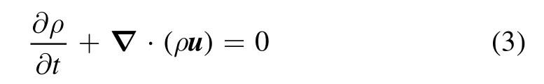
Momentum conservation equations:
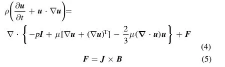
Energy conservation equations:
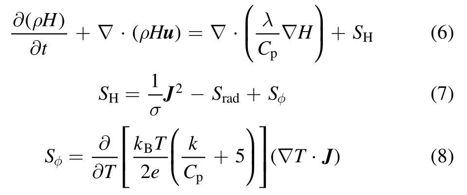
The plasma heat sourceSHincludes three terms;the first term represents Joule heat,the second team represents thermal radiation of the arc,and the third term represents viscous dissipation due to flow,which is the energy carried by the current.
During arc combustion,the thermal radiationSradcontributes to the transfer of energy of the arc in the arc chamber,so it is significant for the calculation of arc energy.The simplified calculation formula ofSradis[43]
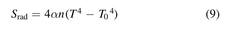
where=/n p p0is the absorption coefficient.
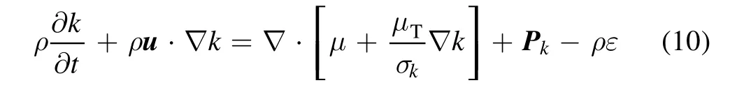
The laminar flow model is commonly used in the modeling of the minitype arc chamber,but in the modeling of the arc chamber with high capacity,due to its large volume,if the turbulence effect is not considered,the calculated results will have a large deviation from the measured results;i.e.generally,the calculated arc motion is faster than the measured results[20].Therefore,in this work,the turbulence effect inside the arc chamber is considered and thek-epsilon turbulence equation is used to model the shear stress transport[3,44].Thek-ε model contains two transport equations forkandε[45].
The transport equation forkis
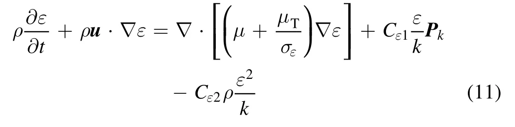
The transport equation forεis
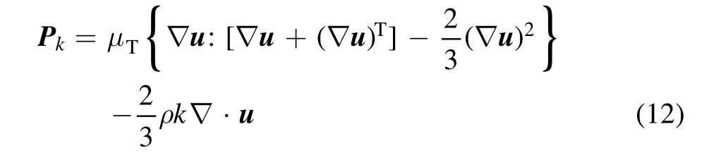
The production term of turbulent kinetic energyPkis
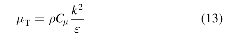
The viscosity of turbulentμTis
Cε1,Cε2,Cμ,σkandσεare five empirical constants in the turbulence models,which depend on the magnitude of the arc current[46,47].As the current involved in this paper is less than or equal to 350 A,the values of these five constants are set toCε1=1.44,Cε2=1.92,Cμ=0.09,σk=1.00andσε=1.30,respectively,according to reference[47].
The coupling between the MHD model and the selfexcited magnetic field generated by the self-excited coil is realized by the method shown in figure 2 in this paper.The density,electrical conductivity,thermal conductivity,specific heat at constant pressure and dynamic viscosity of the arc plasma are considered as the functions of pressure and temperature[48-50].
At the cathode and anode,according to the energy conservation equation of electrons and ions,the thermal boundary conditions of the cathode are as follows:
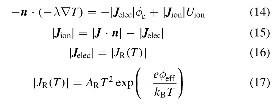
whereUion=7.9 eVis the ionization potential of the arc plasma[51];ϕc=4.65 eV is the surface work function of the cathode material with a copper electrode and air as the working gas[52];∣·∣J nis the surface current density module;andϕeff=2.6 V is the effective work function of the copper electrode[51].
The thermal boundary conditions of the anode are
whereϕa=4.65 eV is the surface work function of the anode material with a copper electrode and air as the working gas[52].
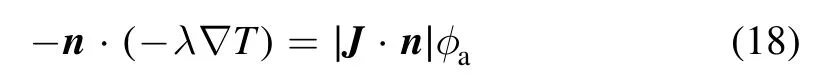
The boundary conditions used in this model are described in figure 3 and table 1.
All the calculations involved in this model are carried out using the finite element method by means of the software COMSOL Multiphysics®V5.6 on the platform of Intel(R)Core(R)CPU I7-11700K@3.60 GHz with 8-core 16-thread parallel computation.The platform memory is 64 G,and the calculation time is no more than 80 h.
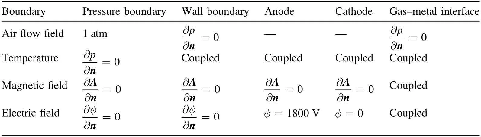
Table 1.Boundary conditions.
3.Simulation results and discussion
3.1.Small current interruption characteristics in traditional structure
The magnetic field[24,53-55]and the airflow field[56,57]are the dominant factors affecting the arc temperature distribution.Figure 4 shows the magnetic field and temperature distribution in the middle cross-section of the traditional structure with an interrupting current of 150 A.For convenient observation,the magnetic field intensity less than 10 mT is not shown in the figure and its values at the arc roots are marked in the figure.In the traditional structure,the arc is cut by the splitter plates at 89.53 ms with an arc current of 118.19 A.The magnetic field intensity in the arc chamber decreases gradually from the center to the periphery.The magnetic field intensities are 22.603 mT and 22.720 mT,respectively,at the anode and cathode arc roots.At 125.7 ms,the arc roots curl up and the magnetic field intensity in the arc chamber decreases.At 163.4 ms,the arc roots on both sides curl up further,and the magnetic field intensity in the arc chamber reduces further with an arc current of 85.38 A.When the arc is cut by the splitter plates,both roots move slowly along the arc runner,which will result in seriously ablation.The high-temperature gas carried by the curled arc root accumulates at the entrance of the arc chamber,which increases the conductivity here as well as the probability of restrike.
Figure 5 shows the arc voltage and current versus time in the traditional structure.Before 50 ms,the arc moves from the contact to the entrance of the arc chamber,and the arc is elongated so the arc voltage rises.At 50-89.53 ms,the arc moves from the entrance of the arc chamber to the splitter plates.At this phase,the rates of arc voltage and current change are the lowest,and the arc is in the process of steady combustion.In order to accelerate the arc extinguishing process,the arc steady combustion time should be shortened as far as possible.After 89.53 ms,the arc is cut by the splitter plates.Although the rates of arc voltage and current change increase,the arc voltage does not reach the power supply voltage within the simulation time,and the interruption is not completed.
Figure 4.The magnetic field and temperature distributions in the middle cross-section of the traditional structure with interrupting current of 150 A.
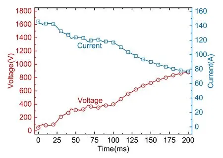
Figure 5.Arc voltage and current versus time in the traditional structure.
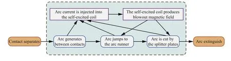
Figure 6.Arc extinguishing principle of SE-DCCB.
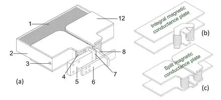
Figure 7.(a)SE-DCCB with improved structure.(b)Magnetic blowout component of traditional structure,(c)magnetic blowout component of improved structure.1-Splitter plate,2-Arc runner,3-Side air outlet,4-Coil,5-Upper busbar,6-Lower busbar,7-Fixed contact,8-Moving contact,12-Split magnetic conductance plate.
3.2.Model of the improved structure
In order to make the SE-DCCB interrupt the small current successfully,combined with the analysis of the magnetic field and arc characteristics in the traditional structure in the previous section,an arc chamber with new magnetic conductance plate according to the arc extinguishing principle of SE-DCCB is designed in this section.A schematic diagram of the arc extinguishing principle of SE-DCCB is given in figure 6.When the contacts separate,the arc is generated between the two contacts,then the coil in series with the arc generates a self-excited magnetic field.The self-excited magnetic field passes through the coil,the magnetic conductance plates and the arc chamber,which constitute a magnetic loop.The self-excited magnetic field is transferred into the arc chamber,and then the arc moves under the influence of the magnetic field.From the analysis in the previous section,when the SE-DCCB interrupts the small current,the arc current injected into the coil is small.The self-excited coil cannot generate sufficient magnetic field to drive the arc to move to the splitter plates.The magnetic field of the arc roots in the traditional structure is small,so it is difficult to make the arc root move along the arc runner quickly.The arc root stagnation not only causes serious partial ablation of the arc runner,but also heats the entrance of the arc chamber for a long time,which increases the probability of restrike to a certain extent[50,53,58].
In order to develop an SE-DCCB capable of interrupting the small current,the duration of the arc root stagnation should be reduced as much as possible,so the magnetic field in the arc chamber is optimized by altering the structure of the magnetic conductance plates in this work.As shown in figure 7,the upper and lower magnetic conductance plates are improved from the integral type(see figures 7(b)and(c)),and the magnetic conductance connections in the traditional structure are eliminated.The magnetic field generated by the coil is strengthened by the iron core and then passes through the front magnetic conductance plates,the arc chamber and the rear magnetic conductance plates to form a magnetic loop.
3.3.Comparison of arc root stagnation phenomenon between two structures of arc chamber
Figure 8 shows the magnetic field and temperature distribution in the middle cross-section of the improved structure with an interrupting small current of 150 A.For convenient observation,the magnetic field intensity less than 10 mT is not shown in the figure and its values at the arc roots are marked in the figure.In the improved structure,the arc is cut by the splitter plates at 82.16 ms,which is earlier than in the traditional structure.During the arc-splitting process,the magnetic field in the arc chamber is larger than that in the traditional structure,and the magnetic field intensities are 25.894 mT and 25.858 mT,respectively,at the anode and cathode arc roots.The larger the magnetic field of the arc roots,the larger the magnetic blowout force of the arc roots,and the faster the movement of the arc roots.At 100-160 ms,the arc roots move to both sides along the arc runner without curling up.At 163.4 ms,the arc current drops to 14.96 A,and the magnetic field intensities are 13.235 mT and 13.172 mT,respectively,at the anode and cathode arc roots.It can be seen that the efficiency of the magnetic field concentrated in the arc chamber with split magnetic conductance plates is much higher,so the magnetic blowout force at the arc roots is larger,and the arc roots can move along the arc runner smoothly.
Figure 9 shows the current density and magnetic blowout force of the anode arc root in the two structures with interrupting current of 150 A.In the traditional structure,the arc column near the arc root bent under the combined influence of magnetic blowout force and airflow field.The arc root is affected by the magnetic blowout force pointing to the bottom left,so the horizontal component is too low to drive the arc root to move fast.Thus,the arc root stagnation phenomenon occurs.Meanwhile,in the improved structure,the bottom left component of the magnetic blowout force at the arc root is small,which makes the arc root move rapidly along the arc runner under the dominant influence of the horizontal component of the magnetic blowout force,and the arc column near the arc root does not bend in a large degree.Along with the arc root moving to the left,the arc cools gradually,so the arc temperature and the conductivity decrease.At 160 ms,the arc near the arc root breaks and the arc tends to be extinguished.
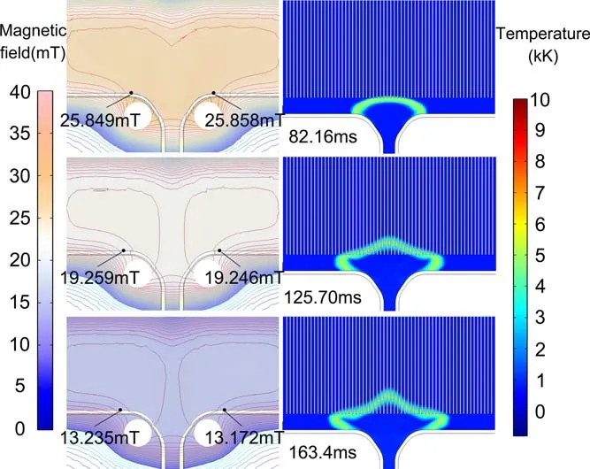
Figure 8.The magnetic field and temperature distributions in the middle cross-section of the improved structure with interrupting current of 150 A.
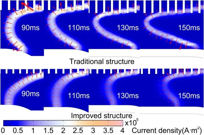
Figure 9.The current density and magnetic blowout force of the anode arc root in the two structures with interrupting currentof 150 A.
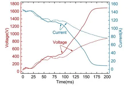
Figure 10.Arc voltage and current versus time in the improved structure compared with the traditional structure.The solid lines represent the improved structure and the dashed lines represent the traditional structure.
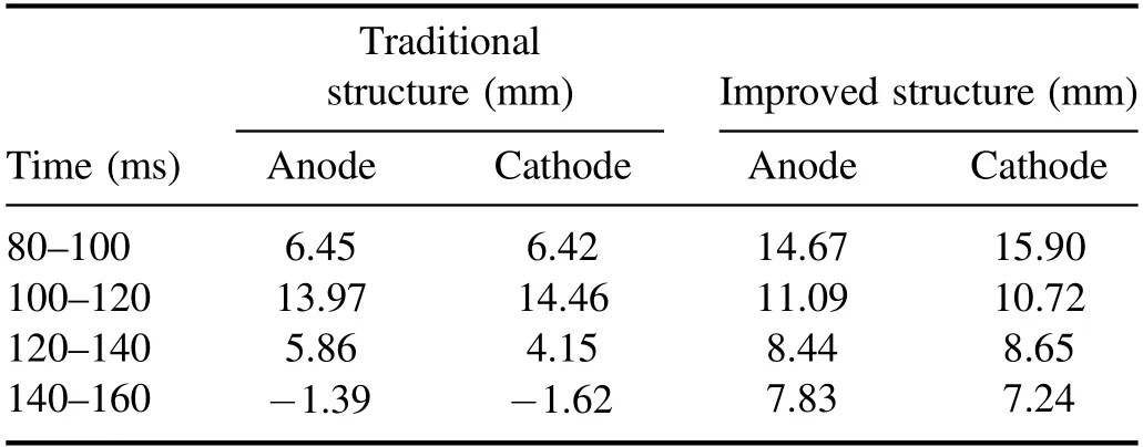
Table 2.The arc root displacement in the two structures with interrupting current of 150 A.
The arc root displacement in the two structures with an interrupting current of 150 A is shown in table 2.In the traditional structure,maximum arc roots displacement happens at 100-120 ms,during which the arc has just been cut by the splitter plates,and the arc column near the arc roots has not been bent in a large radian degree.Then the curvature of the arc column near the arc roots increases and the horizontal component of the magnetic blowout force on the arc roots decreases.At 140-160 ms,under the combined influence of magnetic blowout force and airflow field,the arc roots undergo reverse movement.While in the improved structure,the maximum arc root displacement happens at 80-100 ms.At this phase,the arc has just been cut by the splitter plates,and the arc column near the arc roots does not bend in a large degree.The horizontal magnetic blowout force at the arc roots is large,so the arc roots move fast.Then the arc column near the arc roots becomes more and more curved,and the horizontal component of the magnetic blowout force on the arc roots becomes smaller and smaller.Different from the traditional structure,the arc roots do not show reverse movement at 140-160 ms,but keep moving to both sides at a certain speed.
Figure 10 shows the arc voltage and arc current versus time in the improved structure compared with the traditional structure.It can be seen that the time period between the arc moving from the entrance of the arc chamber and being cut by the splitter plates is 60-82.16 ms,which is significantly shorter than that in the traditional structure.No arc root stagnation occurs throughout the entire splitting process.While the arc is cut by the splitter plates,the arc roots on both sides continue to extend along the arc runner.The arc voltage rises sharply;meanwhile the arc current drops sharply.The arc power decreases and its heating effect in the arc chamber is weakened.When the heat dissipation is greater than the heat generated by the arc,the arc temperature begins to decrease and the conductivity decreases further.At 163.4 ms,the arc voltage approaches the power supply voltage,and the arc is extinguished.
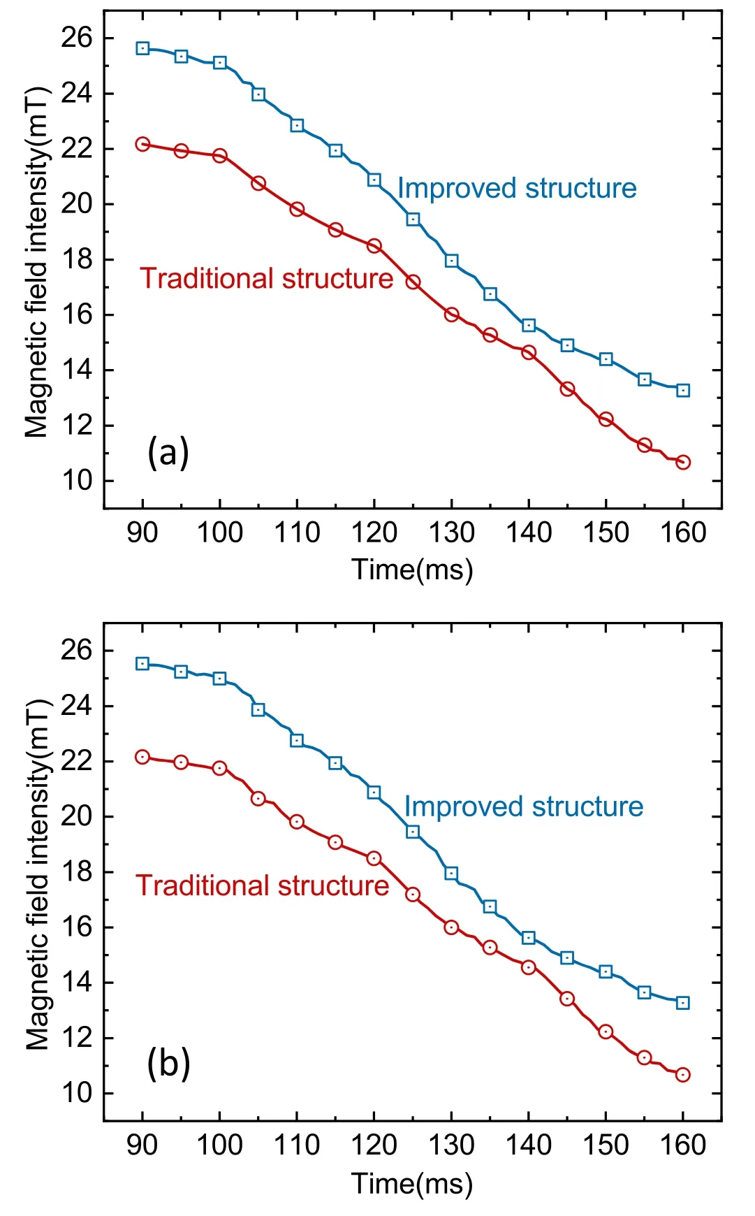
Figure 11.The magnetic field intensity versus time at the arc roots.(a)The magnetic field intensity versus time at the anode arc root,(b)the magnetic field intensity versus time at the cathode arc root.
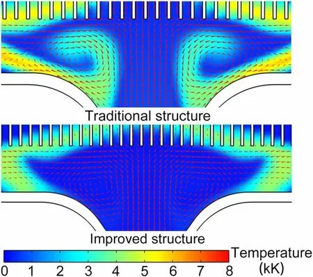
Figure 12.Temperature and airflow velocity distribution at the arc roots in the arc chamber at 150 ms with interrupting current of 150 A.
3.4.Arc root stagnation and curling of small current interruption
From the analysis above,eliminating arc root stagnation is good for small current interruption,and arc root stagnation is often accompanied by arc root curling.Arc root curling will increase the temperature of the entrance of the arc chamber,which makes small current interruption more difficult.The self-excited magnetic field is closely related to arc root stagnation and curling.In-depth analysis of the relationship between the arc root stagnation and the self-excited magnetic field can provide theoretical support to solve the problem of small current interruption in an SE-DCCB.The magnetic field and airflow field at the arc root in the traditional and improved structures are analyzed by contrasting in this section.
Figure 11 shows the magnetic field versus time at the arc roots.It is easy to see that the magnetic field at the anode and cathode arc roots is symmetrical.The magnetic field intensity at the arc roots in the traditional structure is less than that in the improved structure at the same time.After 100 ms,the arc enters the splitter plates completely,and the magnetic field at the anode and cathode arc roots in both structures begins to decline significantly.Combined with figure 10,it can be seen that the change of the magnetic field at the arc roots is synchronized with the change of the arc current,and both of them have the inflexion point at almost the same time.At 90-160 ms,the magnetic field at the arc roots in the improved structure is always above that of the traditional structure,while the arc current curve in the improved structure is always below that in the traditional structure(figure 10).This indicates that the improved structure has a higher efficiency of magnetic field conversion,so the magnetic field in the arc chamber is stronger.Therefore,the magnetic blowout force at the arc roots in the improved structure is larger,which not only accelerates the movement speed of the arc roots but also inhibits the curling of arc roots effectively.
The distribution of the airflow field can explain the curling of the arc roots.Figure 12 shows the distribution of the temperature and airflow field at the arc roots in the two structures at 150 ms.The high-temperature gas at the arc roots curls up under the action of airflow vortexes in the traditional structure,and the magnetic blowout force is not enough to drive the arc roots to move quickly along the arc runner.The long-time arc burning and heating at the entrance of the arc chamber alters the airflow field in the arc chamber.The air vortexes at the entrance of the arc chamber under the action of high-temperature gas are strengthened.At 140-160 ms,the force exerted by the vortexes is greater than the magnetic blowout force at the arc roots,and the arc roots move in the reverse manner(table 2).In the improved structure,the magnetic field at the arc roots is larger,and the arc roots move faster along the arc runner.The arc does not heat the entrance of the arc chamber for a long time,so the airflow vortexes are weakened gradually with the arc roots moving to both sides,and the arc roots do not curl up.
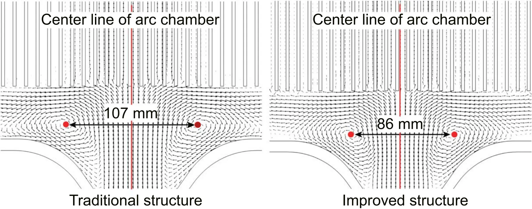
Figure 13.Air flow direction distribution in the arc chamber at 150 ms with interrupting current of 150 A.
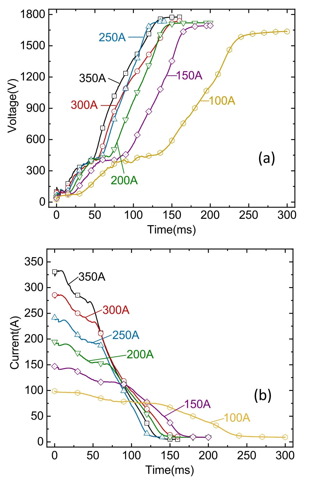
Figure 14.Arc voltage and current versus time in the improved structure with different levels of current.(a)Arc voltage versus time,(b)arc current versus time.
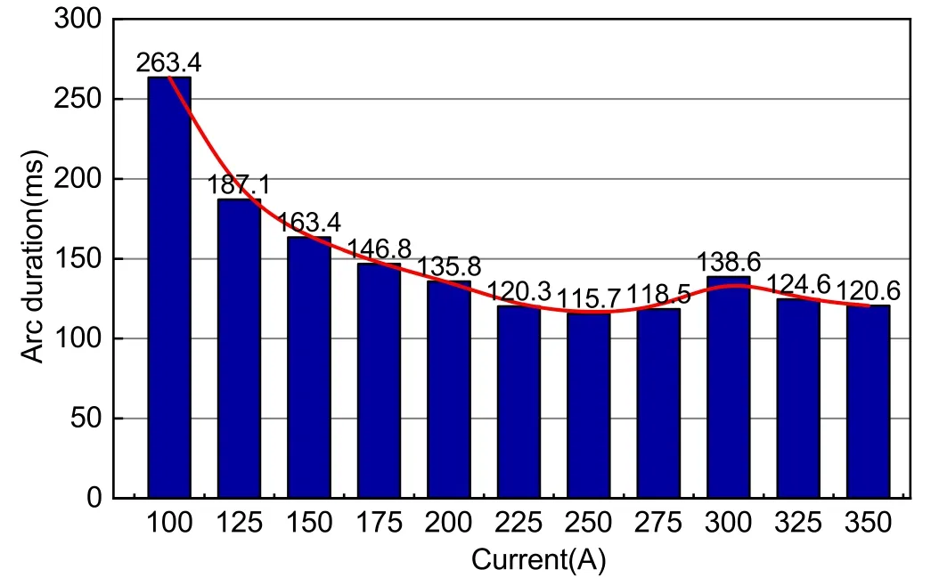
Figure 15.The arc duration time in the improved structure when interrupting different current levels.
The airflow vortexes are the significant factors in relation to the movement of the arc roots.In order to investigate the airflow vortexes and their interaction mechanism with the arc root movement in more depth,the airflow field distributions of the two structures at 150 ms with an interrupting current of 150 A are shown in figure 13.In both structures,the airflow vortexes are symmetrical about the center line of the arc chamber.The left and right sides of the airflow vortex rotation direction are counterclockwise and clockwise,respectively.In the traditional structure,the center distance of the left and right airflow vortexes is 107 mm,while in the improved structure,the distance is 86 mm.In the traditional structure,the action radius of the airflow vortexes is larger.As the arc roots are subject to the action of the vortexes of airflow,the airflow field is opposite to the magnetic blowout force,which is the dominant reason for the reverse movement of the arc roots at 140-160 ms.In the improved structure,the action radius of the airflow vortexes is short,and the reverse airflow field near the arc roots is weak,so the arc roots can move along the arc runner under the combined action of the magnetic blowout force and airflow field smoothly.In the design of such product,the magnetic field in the arc chamber can be optimized by altering the magnetic conductance structure.Thus,the arc movement can be accelerated when the small current is interrupted.
3.5.Different levels of small current interruption characteristics in improved structure
Taking the improved structure as the research object,the simulations of interruption characteristics with the current range of 100-350 A are carried out.The arc voltage and current versus time in the improved structure with different levels of current are shown in figure 14.The arc duration time can be divided into three phases.The first phase is the period when the arc moves from the contact to the entrance of the arc chamber.The rates of arc voltage and current change are rapid in this phase.The second phase is the period when the arc moves from the entrance of the arc chamber to the splitter plates.In this phase,the rates of the arc voltage and current change are low.The third phase is the period when the arc is cut by the splitter plates and then extinguished.In this phase,the rates of arc voltage and current change are the fastest.The duration of the second phase is significantly different when interrupting different levels of current.The duration of the second phase is 20 ms at 350 A and 90 ms at 100 A.With the decrease of the interrupting current,the duration of the second phase increases significantly.The longer the second phase lasts,the more obvious its heating effect on the arc chamber is,which increases the probability of interruption failure.Under the influence of the heating effect,the arc runner and the splitter plates will be ablated.Reducing the arc stagnation time of the second phase is key to shortening the arc duration time and realizing interruption of small current successfully.
Figure 15 shows the arc duration time in the improved structure when interrupting different levels of current.When the current increases from 100 A to 200 A,the arc duration time decreases gradually.When the interrupting current is in the range of 225-350 A,the arc duration time fluctuates around 130 ms.This is because when the current is less than 200 A,the arc duration time mainly depends on the self-excited field generated by the coil.Within this current range,the magnetic field in the arc chamber increases with the increase of the arc current,and the arc duration time decreases.When the current is more than 200 A,the arc energy increases with the increase of the arc current.The heating capacity of the arc in the arc chamber is enhanced,and the high-temperature gas accumulates in the arc chamber.The aggregation of high-temperature gas in the arc chamber weakens the effect of the magnetic field on the arc motion,so the arc duration time is no longer significantly reduced.
4.Conclusion
Taking actual products as the research object,the small current interruption characteristics in a large-capacity SE-DCCB are investigated in this work.The magnetic conductance plate structure is optimized here.The influence factors of the arc root stagnation and the causes of the airflow vortexes are analyzed.The following conclusions can be drawn from the results.
(1)The magnetic blowout force interacts with the airflow field in the traditional structure.The reverse airflow field counteracts the effect of the magnetic blowout force and causes arc root stagnation.The airflow vortexes increase and the arc roots curl up,which increases the probability of restrike.That is the reason why small current interruption is difficult in SE-DCCB.
(2)In the improved structure,the magnetic blowout force at the arc roots is enhanced,and the arc roots move along the arc runner under the combined action of the magnetic blowout force and the airflow field.The temperature at the entrance of the arc chamber decreases gradually,and the airflow vortexes are weakened,so the high-temperature gas no longer gathers in the arc chamber.
(3)The improved structure has a higher utilization rate of magnetic field.It can generate a stronger magnetic field in the arc chamber with the same arc current,because the direction of the magnetic blowout force is optimized.It can be seen that the improved structure has better small current interruption performance.
(4)The improved structure can interrupt small current in the range of 100-350 A successfully.This structure has a phase in which the arc voltage and current change rate is slow when interrupting small current,and the duration of this phase decreases as the interrupting current increases,which can improve the speed of the interrupting small current.
Acknowledgments
This work was supported by National Natural Science Foundation of China(No.51977132),the Key Special Science and Technology Project of Liaoning Province(No.2020JH1/10100012),and the General Program of the Education Department of Liaoning Province(No.LJKZ0126).
ORCID iDs
猜你喜欢
杂志排行
Plasma Science and Technology的其它文章
- An equivalent model of discharge instability in the discharge chamber of Kaufman ion thruster
- Discharge and jet characteristics of gliding arc plasma igniter driven by pressure difference
- Investigation of stimulated growth effect using pulsed cold atmospheric plasma treatment on Ganoderma lucidum
- Comparative study of pulsed breakdown processes and mechanisms in self-triggered four-electrode pre-ionized switches
- Nanosecond laser preheating effect on ablation morphology and plasma emission in collinear dual-pulse laser-induced breakdown spectroscopy
- Interaction of an unwetted liquid Li-based capillary porous system with high-density plasma