Switchable down-,up-and dual-chirped microwave waveform generation with improved time–bandwidth product based on polarization modulation and phase encoding
2022-08-01YuxiaoGuo郭玉箫MuguangWang王目光HongqianMu牟宏谦andGuofangFan范国芳
Yuxiao Guo(郭玉箫), Muguang Wang(王目光), Hongqian Mu(牟宏谦), and Guofang Fan(范国芳)
Institute of Lightwave Technology,Key Laboratory of All Optical Network and Advanced Telecommunication Network,Ministry of Education,Beijing Jiaotong University,Beijing 100044,China
Keywords: microwave photonics,linearly chirped waveform generation,time–bandwidth product
1. Introduction
Linearly chirped microwave waveforms have been widely used in modern radar systems. Due to the superior pulse compression capability of linearly chirped waveform, the detection range and range resolution can be increased greatly.[1,2]As the pulse compression performance is proportional to the time–bandwidth product(TBWP),linearly chirped waveforms with large TBWP are highly preferred in pulse compression radar systems.However,the conventional methods to generate linearly chirped waveforms by using the electrical techniques suffer from low central frequency and narrow bandwidth due to the electronic bottleneck,which may be not suitable for future high precision radar systems. The linearly chirped waveform generated by modern photonic technique is a promising method to solve the problems in electronic systems,due to the advantages of low insertion loss,wide bandwidth,and immunity to electromagnetic interference.[3]
A number of efforts have been made to generate linearly chirped waveform with photonic technique. These methods can be mainly divided into two kinds according to the types of generated signals. The first one is the singlechirped waveform generation, including direct space-to-time mapping,[4,5]frequency-to-time mapping,[6–8]optically injected semiconductor laser,[9,10]Fourier domain mode locked optoelectronic oscillator[11]and heterodyning method.[12–14]One of the application limitations of single-chirped waveform is its knife-edge-type ambiguity function,which reduces the range-Doppler resolution. The dual-chirped waveform that consists of an up-chirped waveform and a down-chirped waveform can be used to improve the range-Doppler resolution. Photonic generation of dual-chirped waveform has been widely studied in recent years. The common methods include integrated optical modulator based methods,[15–19]cascading modulators based methods,[20–23]sweeping laser based methods,[24]and optically injected semiconductor laser based methods.[25,26]All methods mentioned above can only generate one kind of linearly chirped waveform, which cannot meet the requirements of multifunctional radar systems.Luckily, a flexible linearly chirped generator which can generate switchable down-chirped, up-chirped and dual-chirped waveforms has been proposed recently.[27]However,the central frequency and bandwidth of the generated waveform are equal to the frequency of local oscillator(LO)and bandwidth of arbitrary waveform generator(AWG),which indicates the central frequency and bandwidth as well as the TBWP are still limited by the electrical systems.
In this paper, a switchable down-, up-, dual-chirped microwave waveform generation technique is proposed by using a dual-polarization dual-parallel Mach–Zehnder modulator (DP-DPMZM) cascaded with a polarization modulator(PolM).By controlling the phase shifts of the radio frequency(RF)signals applied to the DP-DPMZM followed by a PolM driven by a parabolic signal,the down-,up-,dual-chirped microwave waveform with simultaneous frequency and bandwidth doubling can be generated and switched. Moreover,the bandwidth of the generated waveform can be enhanced by replacing the conventional parabolic signal with a splitting parabolic signal. Also, the time duration can be increased by using the phase-encoding technique.Hence,the TBWP can be increased significantly. Simulation experiments are conducted and the switchable down-,up-,dual-chirped microwave waveforms with TBWP of 8, 160 and 10240 are generated. The TBWP can be enlarged further by splitting parabolic signal into more pieces and using a longer length sequence to encode the phase.
2. Principle
Figure 1(a)shows the structure of the switchable down-,up-and dual-chirped microwave waveform generator. A lightwave emitted from a laser diode(LD) is launched into a DPDPMZM. As shown in Fig. 1(b), the DP-DPMZM is an integrated device which includes two DPMZMs, a 90°polarization rotator and a polarization beam combiner(PBC).The DPMZM consists of two sub-MZMs which operate in pushpull mode and a main MZM.Vb1,Vb2,Vb4andVb5are the direct current (DC) bias voltages of the four sub-MZMs, respectively. Similarly, the DC bias voltages of the two main-MZMs are represented byVb3andVb6. An RF signal from an LO is split into four paths to drive the four sub-MZMs of the DP-DPMZM with each path undergoing different phase shiftθi(i=1,2,3,4). The phase shifts are controlled by using adjustable phase shifters. All the sub-MZMs are biased at minimum transmission point(MITP)and the two main MZMs are biased at quadrature transmission point(QTP)by adjusting the DC biasesVbi. The principal axes of PBC in the DP-DPMZM is aligned with those of the PolM by a polarization controller(PC).In the PolM,the complimentary parabolic phase modulation in the two polarization states is achieved. Next,PC2 is employed to make sure one of the polarization directions of the optical signal from the PolM is 45°relative to one of the principal axes of the polarization beam splitter(PBS).After passing the PBS, the optical signal is transmitted into a balanced photodetector(BPD)for optical to electrical conversion.
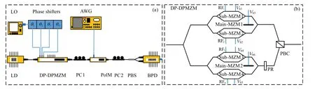
Fig.1. (a)The structure of the generator. (b)The diagram of the DP-DPMZM.
The optical field of the linearly polarized lightwave emitted from the LD can be expressed asE(t)=E0ejω0t, whereE0andω0are the amplitude and angular frequency of the lightwave, respectively. The four driving microwave signals can be written asVicos(ωmt+θi),(i=1,2,3,4),whereVidenotes the amplitude of each RF signal,ωmdenotes the angular frequency, andθidenotes the initial phase of each RF signal,which can be controlled by adjustable phase shifter. Without loss of generality,θ1can be fixed to 0. By controlling the DC biases,all the four sub-MZMs are biased at MITP and the two main-MZMs are biased at QTP.Hence the optical field at the output of the DP-DPMZM is given by
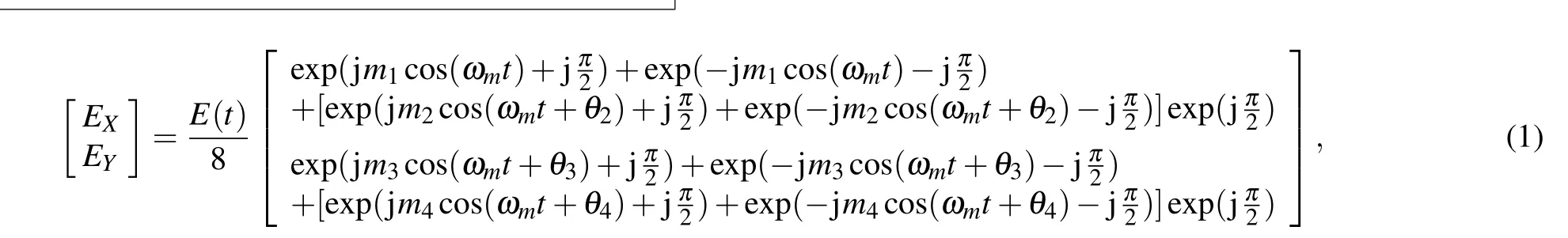
wheremi=πVi/Vπis the modulation index of each sub-MZM andVπis the half-wave voltage of each sub-MZM. Here we assume that the modulation indices of the sub-MZMs are identical,i.e.,m1=m2=m3=m4=m. Under small signal conditions,Eq.(1)can be simplified as
whereJ1(·)is the first kind of Bessel function of the first order. Next,the principal axes of PBC in the DP-DPMZM are aligned with those of the PolM by PC1. A parabolic signal denoted asVss(t)is generated by an AWG and used to drive the PolM.The output of the PolM can be given by
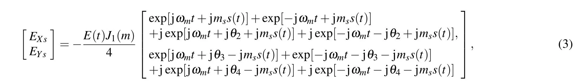
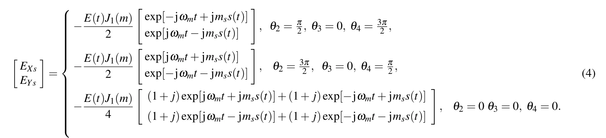
wherems=πVs/VπPolMis the modulation index of the PolM,andVπPolMis the half-wave voltage of the PolM.By controlling the phase shifts of the four driving RF signals applied to the DP-DPMZM,Eq.(3)can be divided into three cases. The detailed expressions are given by
Then the modulated signal is controlled by PC2 to adjust the polarization state ofEXsorEYsat an angle of 45°with respect to one principal axis of the PBS.Thus the optical field at outport 1 and outport 2 of the PBS can be expressed as

Hence the optical current output from the BPD is given by
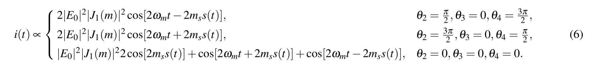
Hereθ3is always set to be 0. Whenθ2=π/2,andθ4=3π/2,the generator operates in down-chirped waveform generation mode and a down-chirped waveform is generated. Whenθ2andθ4are set to be 3π/2 andπ/2,respectively,the generator operates in up-chirped waveform generation mode and an upchirped waveform is generated. When there is no phase shift,the generator operates in dual-chirped waveform generation mode,and a dual-chirped waveform is generated along with a baseband component that cannot be radiated by the antenna.Note that the frequency and bandwidth doubling operation are achieved simultaneously without any filters.
Mathematically, the parabolic signals(t) can be written as
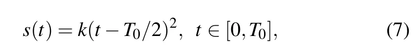
wherek=4/T20is the parabolic coefficient,T0is the temporal duration. According to Eq.(7),when the generator operates in down-chirped waveform generation mode, the instantaneous angular frequency of the generated waveform can be expressed as
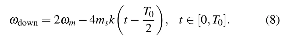
When the generator operates in up-chirped waveform generation mode, the instantaneous angular frequency of the generated waveform can be expressed as
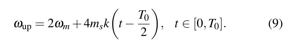
When the generator operates in dual-chirped waveform generation mode,the instantaneous angular frequency of the generated waveform can be expressed as
For all these three cases, the bandwidths and time durations of the generated signals are all 8ms/(πT0)andT0. Hence the TBWP can be calculated as
As can be seen,the TBWP of the generated waveform is proportional to the modulation index of the PolM. However, the limited modulation index of the PolM limits the bandwidth of the generated waveform and results in a low TBWP. To further improve the TBWP, the splitting parabolic signal can be used to replace the conventional parabolic signal to drive the PolM.[28]The splitting parabolic signal is obtained by splitting the conventional parabolic signal intoNpieces within one temporal duration. The splitting parabolic signal can be mathematically expressed as

whereNis the number of the pieces andan(n=1,2,...,N)is the value to make the peak amplitude of each piece equal.It is well-known that the constant item has no influence to the differential operation. Therefore,the bandwidths of the generated chirp waveforms are greatly increased and can be denoted as 4Nms/(πT0). Hence the corresponding TBWP is

Obviously,the TBWP increasesN/2 times compared with the original parabolic phase modulation. Besides the splitting parabolic phase modulation, the TBWP can be further improved by phase-encoding technique.[29]The pseudo-random binary sequence(PRBS)is used to encode the phase,which is given by
whereMis the length of the PRBS,andci=±1 is the value of theith bit. Thus the phase-encoding splitting parabolic function can be expressed as

where⊗represents convolution operation. By usings3(t) to drive the PolM, the time duration of the generated waveform increasesMtimes. Hence the TBWP can be expressed as

As can be seen,the TBWP is further increasedMtimes. Compared with the original parabolic phase modulation,the TBWP increasesMN/2 times in total by using the splitting parabolic signal modulation and phase-encoding technique.
3. Simulation and discussion
Numerical simulation experiments based on the schematic diagram as shown in Fig.1 are conducted to verify the feasibility of the proposed technique.A lightwave with the power of 12 dBm is emitted from an LD with the linewidth of 10 MHz and center wavelength of 1550 nm. Then the lightwave is transmitted into a DP-DPMZM driven by four RF signals which are generated by splitting a RF signal with frequency of 20 GHz into four paths with each path undergoing a phase shift by phase shifter. The half-wave voltage and inserted loss of all the sub-MZMs are 4 V and 5 dB.The extinction ratios of the sub-MZMs are set to be 30 dB.All the sub-MZMs are biased at MITP and the two main MZMs are biased at QTP.The half-wave voltage of the PolM is set to be 3.3 V and the modulation index of PolM is set to beπ,which means the peak voltage of the driving signal is 3.3 V.
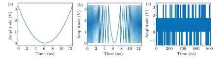
Fig.2. (a)The conventional parabolic signal s(t). (b)The splitting parabolic signal s2(t). The phase-encoding splitting parabolic signal s3(t).
Firstly, the generator is controlled to operate in downchirped waveform generation mode (θ2=π/2 andθ4=3π/2). The driving signal of the PolM is conventional parabolic signals(t)whose profile is shown in Fig.2(a). The time duration is set to be 12.8 ns. Figures 3(a), 3(b)and 3(c)show the generated waveform, frequency-time diagram and corresponding spectrum, respectively. The frequency-time diagram is calculated by using the short-time Fourier transform (STFT). It is used to show the instantaneous frequency of the signal. For the down-chirped waveform, the slope of the frequency-time curve is negative,which means the instantaneous frequency of the generated waveforms is decreasing with time. While for the up-chirped waveform, the slope of the frequency-time curve is positive,which means the instantaneous frequency of the generated waveforms is increasing with time. As can be seen from Fig.3(c),the bandwidth of the generated signal is approximately 0.625 GHz, which means the TBWP is only 8 due to the time duration is 12.8 ns.The autocorrelation is shown in Fig.3(d),from which we can see the full width at half maximum(FWHM)of the compressed pulse is approximately 1.927 ns,corresponding to a pulse compression ratio (PCR) of 6.642. Also, the peak-to-side lobe ratio(PSLR)is 7.70 dB.
The driving signal of PolM is then changed into a splitting parabolic signals2(t) which is shown in Fig. 2(b). The splitting number is set to be 40. Figures 4(a), 4(b), 4(c) and 4(d) show the generated waveform, frequency-time diagram,spectrum and autocorrelation,respectively. It can be seen that a down-chirped waveform with central frequency and bandwidth of 40 GHz and of 12.5 GHz is generated and the time duration is 12.8 ns. Hence the TBWP is 160. From Fig.4(d),the FWHM is approximately 0.0804 ns,so the PCR increases to 159.2. The PSLR of the compressed pulse is 6.77 dB.
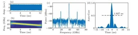
Fig. 3. The generated waveform and corresponding performance when the generator is in down-chirped waveform generation mode and the driving signal is s(t): (a)the temporal waveform,(b)frequency-time diagram,(c)spectrum,(d)autocorrelation.
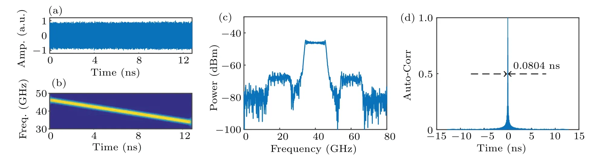
Fig. 4. The generated waveform and corresponding performance when the generator is in down-chirped waveform generation mode and the driving signal is s2(t): (a)the temporal waveform,(b)frequency-time diagram,(c)spectrum,(d)autocorrelation.
To improve the TBWP further,the driving signal of PolM is changed into phase-encoding splitting parabolic signals3(t),which is shown in Fig. 2(c). A 64-bit binary code is used to encode the phase. Figure 5(a)shows the generated waveform.The instantaneous frequency of the signal in the red dashed box of Fig. 5(a) is shown in Fig. 5(b). Figures 5(c) and 5(d)show the corresponding spectrum and autocorrelation,respectively. The time duration is extended to 819.2 ns while the bandwidth is still 12.5 GHz. Therefore, the TBWP increases to 10240. Even though the FWHM of the compressed pulse is still about 0.0804 ns,the PCR is up to 10189.05 thanks to the increasing time duration. The PSLR of the compressed pulse is 6.74 dB. It should be noted that in theory the TBWP can be potentially increased further by splitting the parabolic signal into more pieces and using longer sequence to encode the phase.
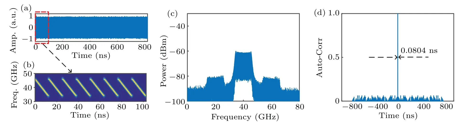
Fig. 5. The generated waveform and corresponding performance when the generator is in down-chirped waveform generation mode and the driving signal is s3(t):(a)the temporal waveform,(b)frequency-time diagram of the signal in red dashed box,(c)spectrum,(d)autocorrelation.

Fig. 6. The generated waveform and corresponding performance when the generator is in up-chirped waveform generation mode and the driving signal is s(t): (a)the temporal waveform,(b)frequency-time diagram,(c)spectrum,(d)autocorrelation.
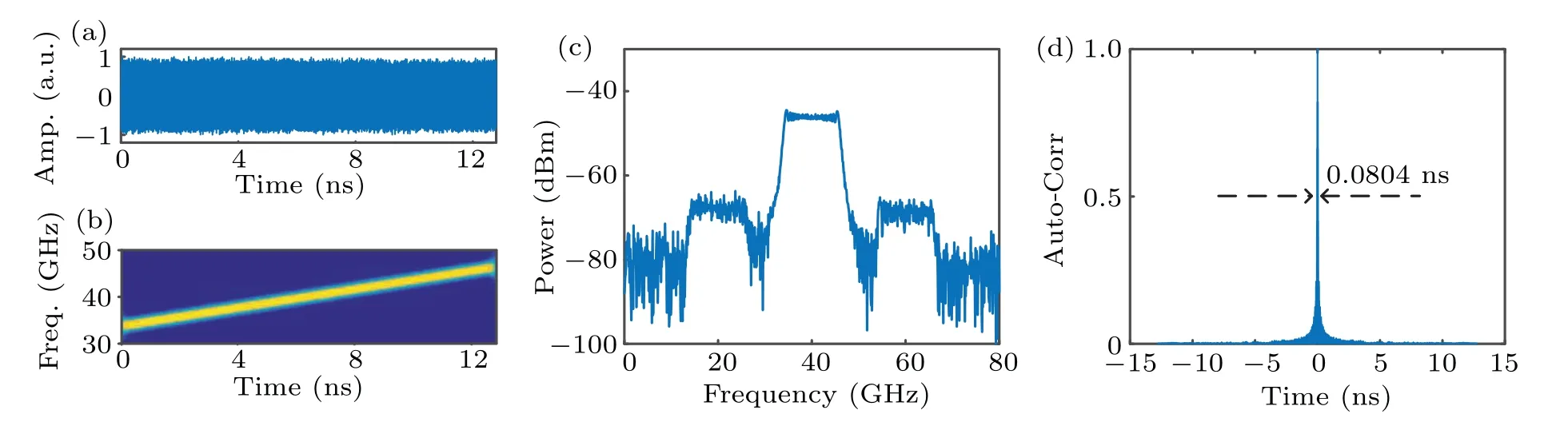
Fig. 7. The generated waveform and corresponding performance when the generator is in up-chirped waveform generation mode and the driving signal is s2(t): (a)the temporal waveform,(b)frequency-time diagram,(c)spectrum,(d)autocorrelation.
Then the phase shifts are changed to control the generator in the up-chirped waveform generation mode (θ2=3π/2 andθ4=π/2). Analogously, the conventional parabolic signals(t) shown in Fig. 2(a) is firstly used to drive the PolM.The generated waveform, instantaneous frequency-time diagram, spectrum and autocorrelation are shown in Figs. 6(a),6(b),6(c)and 6(d).As expected,an up-chirped waveform with a duration and central frequency of 12.8 ns and 40 GHz is obtained. The bandwidth is 0.625 GHz,and hence the TBWP is 8.The FWHM of the compressed pulse is 1.927 ns,so the PCR is also approximately 6.642. The PSLR of the compressed pulse is about 7.66 dB. Then the splitting parabolic signal with 40 pieces shown in Fig. 2(b) is used to drive the PolM.Figures 7(a), 7(b), 7(c) and 7(d) show the generated temporal waveform,frequency-time diagram,spectrum and autocorrelation, respectively. Similar to the down-chirped waveform generation mode with splitting parabolic driving signal,an upchirped waveform with the instantaneous frequency increasing from 33.75 GHz to 46.25 GHz in the duration of 12.8 ns is generated. Therefore, the TBWP is 160. From Fig.7(d), we can see that the FWHM of the compressed pulse is 0.0804 ns, so the PCR is 159.2. The PSLR of the compressed pulse is about 6.74 dB. Next, the phase-encoding splitting parabolic signal shown in Fig.2(c)is employed to improve the TBWP further and the reciprocal results are shown in Fig. 8. Figure 8(a)shows the temporal waveform of the generated signal. As can be seen, the time duration increases to 819.2 ns. Figure 8(b)shows the instantaneous frequency of the waveform in the red dashed box of Fig.8(a). The spectrum of the generated signal is shown in Fig. 8(c), from which we can see the bandwidth is still 12.5 GHz. Hence the TBWP is 10240. The autocorrelation is shown in Fig. 8(d). The FWHM of the compressed pulse is still 0.0804 ns,which indicates the PCR is 10189.05.The PSLR of the compressed pulse is about 6.75 dB.
Finally, we simulate the case when the generator operates in dual-chirped waveform generation mode (θ2=0 andθ4=0). As analyzed above, the conventional parabolic signals(t) shown in Fig. 2(a) is firstly used to drive the PolM.The generated waveform, frequency-time diagram and spectrum are shown in Figs. 9(a), 9(b) and 9(c) respectively. It can be seen that a dual-chirped waveform with central frequency and bandwidth of 40 GHz and 0.625 GHz is generated while a component at baseband is also generated. However,the component at baseband cannot be radiated to free space by the antenna or can be easily filtered out by an electrical high pass filter (HPF). Figure 9(d) shows the waveform after filtered by an HPF. The TBWP of the generated waveform is only 8. Figure 12(a) presents the autocorrelation of the generated dual-chirped waveform when the driving signal of the PolM iss(t). The FWHM of the compressed pulse is only 2.075 ns,corresponding to a little PCR of 6.169. The PSLR of the compressed pulse is about 6.50 dB.
As can be seen in Fig. 9, the bandwidth of the generated dual-chirped waveform is very narrow, only approach to 0.625 GHz. To improve the bandwidth,the splitting parabolic signal shown in Fig. 2(b) is used to drive the PolM. Figures 10(a)–10(c)correspond to the waveform output from the BPD and its frequency-time diagram as well as the spectrum.Figure 10(d) shows the waveform after an HPF. Clearly, a dual-chirped waveform with bandwidth of 12.5 GHz and duration of 12.8 ns is generated, which means the TBWP increases to 160. Figure 12(b) presents the autocorrelation of the generated dual-chirped waveform when the driving signal of the PolM iss2(t). As can be seen, the FWHM decreases to 0.0806 ns, resulting in a PCR of 158.81. The PSLR of the compressed pulse is about 7.80 dB.
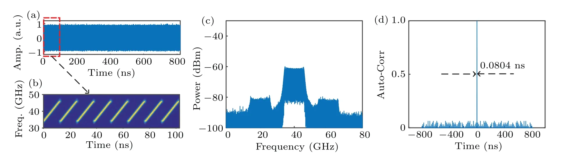
Fig.8.The generated waveform and corresponding performance when the generator is in up-chirped waveform generation mode and the driving signal is s3(t): (a)the temporal waveform,(b)frequency-time diagram of the signal in red dashed box,(c)spectrum,(d)autocorrelation.

Fig. 9. The generated waveform and corresponding performance when the generator is in dual-chirped waveform generation mode and the driving signal is s(t): (a)the temporal waveform,(b)frequency-time diagram,(c)spectrum,(d)the generated waveform after an HPF.
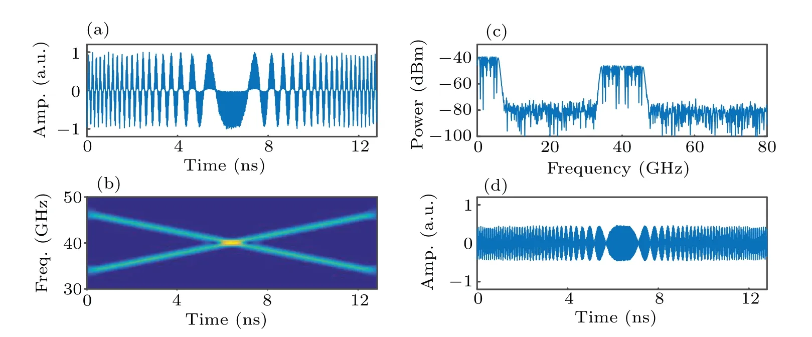
Fig. 10. The generated waveform and corresponding performance when the generator is in dual-chirped waveform generation mode and the driving signal is s2(t): (a)the temporal waveform,(b)frequency-time diagram,(c)spectrum,(d)the generated waveform after an HPF.
At last,the phase-encoding splitting parabolic signals3(t)shown in Fig. 2(c) is employed. Figure 11(a) shows the generated waveform. The frequency-time diagram shown in Fig. 11(b) is the STFT of waveform in the red dashed box of Fig. 11(a). Figure 11(c) shows the spectrum of the generated waveform. A phase-encoding dual-chirped waveform with central frequency of 40 GHz and bandwidth of 12.5 GHz is generated even though a baseband component exists. Figure 11(d)shows the generated dual-chirped waveform after an HPF. The TBWP approaches to 10240 and can be increased further. Figure 12(c) presents the autocorrelation of the generated dual-chirped waveform when the driving signal of the PolM iss3(t). The FWHM is still 0.0806 ns while the temporal duration of the waveform reaches 819.2 ns,leading to a PCR of 10163.77. The PSLR of the compressed pulse is about 7.79 dB.

Fig. 11. The generated waveform and corresponding performance when the generator is in dual-chirped waveform generation mode and the driving signal is s3(t): (a)the temporal waveform,(b)frequency-time diagram of the signal in red dashed box,(c)spectrum,(d)the generated waveform after an HPF.
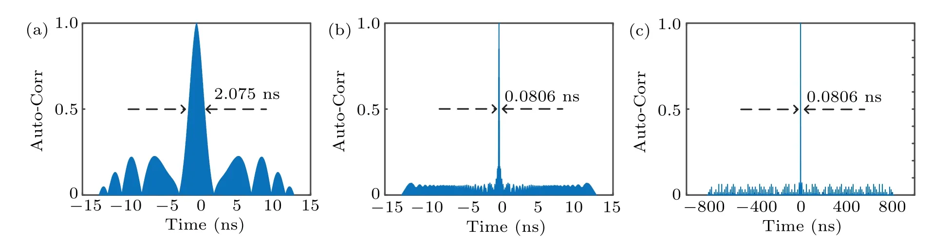
Fig.12. The autocorrelations of the generated dual-chirped waveforms when the driving signal is(a)s(t),(b)s2(t)and(c)s3(t).
It should be noted that although the proposed method can generate the switchable down-, up- and dual-chirped waveform with significantly increased bandwidth by splitting the parabolic signal into some pieces,the maximum splitting number is limited by the sampling rate of the AWG and the maximum bandwidth of the generated waveform is also limited by the bandwidth of the optical devices such as the modulators and photodetectors. In addition, the length of the PRBS which is used to encode the phase is also limited by the memory length of the AWG.Hence,the TBWP can not be enlarged arbitrarily and will be restricted by the sampling rate and memory length of the AWG as well as the bandwidth of the optical devices.
4. Conclusions
A switchable down-, up- and dual-chirped microwave waveform generation technique has been proposed and numerically demonstrated by simply controlling the phase shifts of RF signals applied to the DP-DPMZM.The TBWP can be enhanced by splitting the parabolic signal into more pieces and using the phase-encoding technique. Simulation results indicate our method can generate switchable down-,up-and dualchirped waveform with TBWP of 8, 160 and 10240. In addition, the proposed method features advantages of filter-free structure and high flexibility,which may find promising applications in future multifunctional radar systems.
Acknowledgements
Project supported by the National Natural Science Foundation of China (Grant Nos. U2006217, 61775015, and 62101027)and the Fundamental Research Funds for the Central Universities(Grant Nos.2021JBZ103 and 2021YJS002).
杂志排行

Chinese Physics B的其它文章
- Real non-Hermitian energy spectra without any symmetry
- Propagation and modulational instability of Rossby waves in stratified fluids
- Effect of observation time on source identification of diffusion in complex networks
- Topological phase transition in cavity optomechanical system with periodical modulation
- Practical security analysis of continuous-variable quantum key distribution with an unbalanced heterodyne detector
- Photon blockade in a cavity–atom optomechanical system