Evolution of surfaces and mechanisms of contact electrification between metals and polymers
2022-06-29LinFengWang王林锋YiDong董义MinHaoHu胡旻昊JingTao陶静JinLi李进andZhenDongDai戴振东
Lin-Feng Wang(王林锋), Yi Dong(董义), Min-Hao Hu(胡旻昊),Jing Tao(陶静), Jin Li(李进), and Zhen-Dong Dai(戴振东)
Jiangsu Provincial Key Laboratory of Bionic Functional Materials,College of Mechanical and Electrical Engineering,Nanjing University of Aeronautics and Astronautics,Nanjing 210016,China
Keywords: contact electrification,surface evolution,material structures,material transfer
1. Introduction
Contact electrification(CE)refers to the phenomenon that charge transfer occurs when two surfaces come into contact and are then separated.[1,2]It is also crucial to many engineering applications, like electrophotography, particle separation technologies,etc.[3–5]Recently, triboelectric nanogenerator (TENG) based on contact- or tribo-electrification has attracted tremendous attention. It has opened a new era for micro and nano energy harvesting, self-powered sensing.[6–9]Despite all this, our understanding of CE mechanism is far from enough,[10,11]especially for polymers that are also the most concerned materials in TENG related research,which in turn limits the material design and relevant technology applications.
There has been a certain number of studies of the fundament of CE, and some viewpoints have been raised. For an insulator,[12]it is believed that there are no free electrons that can move between contact surfaces, and only a few nonequilibrium electrons with high energy on the surface can be transferred. Ions can also act as charge transfer medium even for materials without free ions.[13,14]In this case, ions come from the water layer that naturally forms on the surface.[15–17]Besides,the perspective that charge transfer through free radicals is also put forward, but it is still not yet understood in depth.[18,19]Though several theories on CE of polymers have been put forward, consensus has never been reached. The long-standing controversy on it becomes more intense as people penetrate deeper into the charge transfer of polymers. And the CE of polymers is overall still ill-understood, ascribed to their complexity.[20–22]Questions on the fundament of charge transfer and the relationship between CE and polymer structures are still quite open.
The CE is closely related to the states of the two contact surfaces, but does the surface state keeps unchanged in the whole CE process? If not, then how does it change, and how does the change exert an influence on CE charge quantity?It is crucial to understand the CE mechanism, especially for the TENG-based energy harvesting and sensing performance.Compared with the CE mechanism, the evolution of surfaces during CE is relatively less probed into and hence is far from clear. In addition,the TENG devices work under different external loads or frequencies, which may also influence the CE charge quantity and performances of devices.[23,24]Some researchers think that the load affects surface charge quantity by changing the contact area.[25]Some other scholars believe that the load causes the molecular chains to break and the dangling bonds to form, which makes the surface more receptive to electrons.[26,27]Even though some studies are on part of the subjects, the aforementioned issues are overall rarely probed into and are still poorly understood. Therefore,in this work,the CE between metals(Al and Cu)and polymers(polytetrafluoroethylene(PTFE),polyimide(kapton),polyethylene terephthalate (PET)) is systematically studied. The evolution of surfaces during CE is emphasized,the relationship between CE and polymer structures is put forward, and the effects of load and contact frequency on CE process and outputs are investigated,which together with the surface analysis,reveal the mechanism of CE between metals and polymers. The findings advance our understanding of the mechanism of CE between metal and polymers,and provide insights into the performance of TENG under various conditions, which sheds light on the design and optimization of CE-based energy harvest and selfpowered sensing devices.
2. Experiments
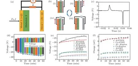
The contact electrification between metals and polymers was systematically studied, and the corresponding schematic is shown in Fig. 1(a) (images of an example are shown in Fig. S1 in supporting information), called the contact mode of tribo-electrification.[28]The CE charge transfers between metal 1 and dielectric 2, and then electrons transfer through the external circuit due to the potential differences between metal 1 and metal 2 caused by the electrostatic induction effect. A homemade device was designed to implement the contact and separation processes between metal and polymer surfaces. The load and frequency of contact could also be adjusted. The contact area was 4 cm×4 cm, the thicknesses of metal and polymer film were 100 μm and 30 μm,respectively.
The criterion for measuring the contact voltage and charge is based on the triboelectric nanogenerator.[29]Under the joint effects of the CE and electrostatic induction, the charge flows back and forth through the external circuit. At this time, the CE charge quantity can be obtained by integrating the external current derived from the measured voltages measured by oscilloscope. Figure 1(b)shows the charge transfer process of two electrodes in a contact and separation process.[28]When the two contact electrodes are in contact (Fig. 1(b)-(i)), an equal-quantity and opposite-sign sign charge is formed on the surfaces of the two materials due to the CE effect. The metal surface loses electrons, while the polymer surface gains electrons. Since the two surfaces with different charges contact each other, there is no potential difference between the two electrodes to drive charge transfer.When the polymer electrode and the metal electrode are separated(Fig.1(b)-(ii)),electrostatic induction causes electrons to transfer from metal 2 to metal 1 to balance the potential.When the separation distance between the two contact electrodes is large enough(Fig.1(b)-(iii)),the charge generated by CE will be transferred completely. When the two contact electrodes gradually approach to each other (Fig. 1(b)-(iv)), the potential difference between the two electrodes decreases,resulting in the reflux of the positive charge. When the two electrodes come together again, there is no potential difference to drive the charge transfer. This is a single circle of CE and charge transfer between two surfaces. Figure 1(c) shows the corresponding measured voltage on resistance during the CE of Al and PTFE,which can be used to estimate the current and contact charge quantity. In order to investigate the mechanism of CE and charge transfer between metal and polymer surfaces,x-ray photoelectron spectroscopy(XPS,Thermo Scientific kalpha+) is used to characterize the surfaces before and after contact.
3. Results and discussion
It is believed that the CE is closely related to the property of material. The CE performances of different materials are compared under the following experimental conditions: the contact load is 2 kg, the contact frequency 4 Hz, the temperature 20°C–25°C, the relative humidity 47%–53%, and the external resistance 7 MΩ. The voltages on the resistances are recorded every five minutes during the experiments until they come to be stable, when CE abilities of the surfaces reach a maximum value. Figure 1(d)shows the voltage of the CE process between Al and PTFE,which increases with contact time and stabilizes after about 60 min. The maximum voltage increases from about-22.5 V at the beginning to-27.5 V(the absolute values are used for comparison). The variation of voltage during CE is believed to be related to surface evolution,especially the creep properties of the polymer.
Figures 1(e) and 1(f) show the variations of measured voltage maximum and the corresponding estimated charge quantity in the process of CE for different materials. It takes time for all the materials to stabilize the CE process, but the surfaces with PTFE take the longest time, and the voltages change most from the beginning to the stable state. The reason is that the PTFE has lower creep resistance than kapton and PET, so the surface property tends to change under load and finally gets to a stable state. When contacting kapton and PET, the Cu surface exhibits a more significant variation of charge quantity than the Al surface. Ascribed to the larger hardness of Cu, the surface asperities force the polymer surface to creep more to some extent,so the variations of voltage and charge quantity of Cu are larger. The voltage and transferred charge quantity vary evidently at three different levels in the CE process, which is mainly determined by the polymer materials. Moreover,the transferred charge quantities are ranked in the following order: PTFE>kapton>PET. The relationship between CE and polymers will be intensively investigated and discussed below. The metal affects the CE as well,but not so much as polymer. Al generates greater charge quantity than Cu,according to the triboelectric series.[30]But there is also an exception in the CE between metals (Al/Cu)and kapton, which is related to the differences in interaction between Al/Cu and kapton surfaces. Compared with Cu,Al is smaller in hardness,and the plastic deformation is larger under load. Therefore,the CE process of Al takes more time to stabilize than that of Cu,which manifests the influence of metals on contact electrification.
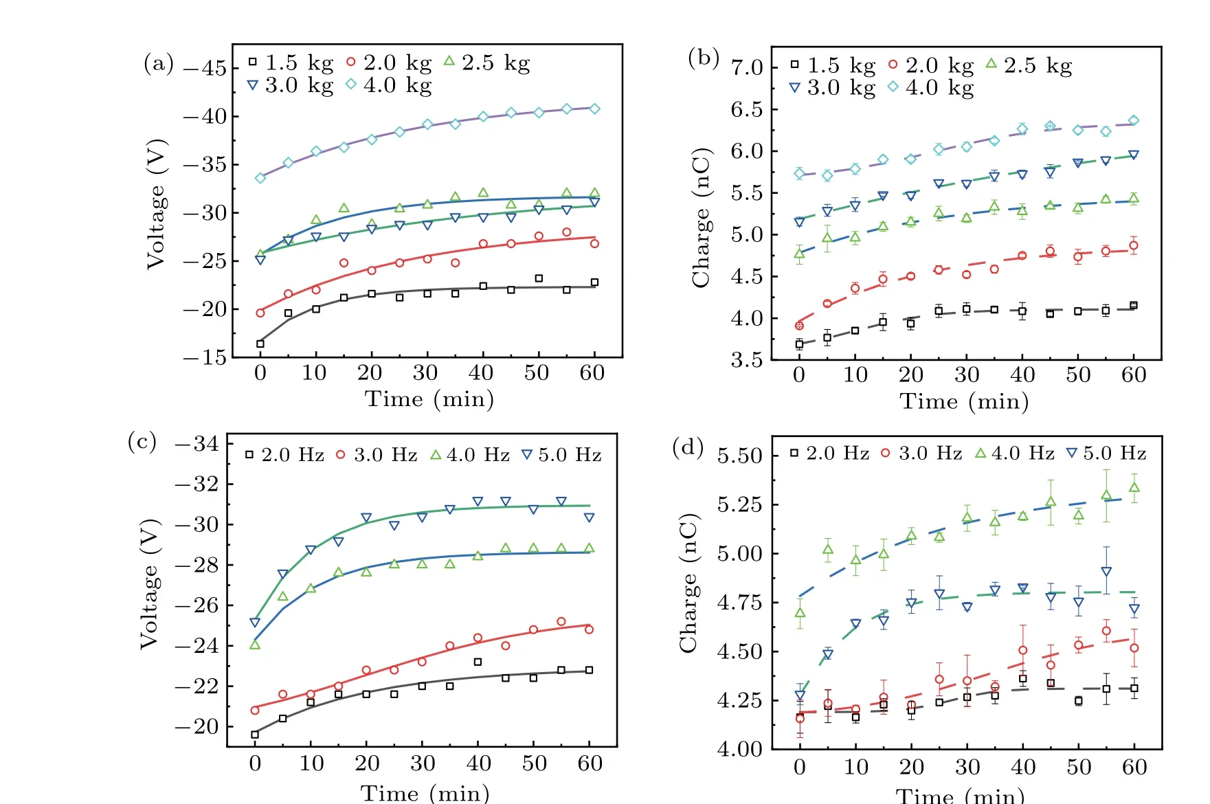
Fig.2. Variations of((a)and(c))voltage and((b)and(d))generated charge during CE process for Al/PTFE under((a)and(b))different loads and((c)and(d))contact frequencies((c)and(d)).
The effect of load on the CE process and the corresponding surface evolution are also studied for different materials. Figures 2(a) and 2(b) show the variations of voltage and charge quantity in the CE process for Al/PTFE under different loads. Voltages and generated charge quantity increase gradually with the contact time, and the difference is that the CE process takes less time to be stable for smaller load than that of larger load. This is mainly because the plastic deformation of Al and the creep of PTFE reach a certain state in a shorter time under a smaller load,and then the actual contact area will not change, and hence the generated charge quantity and voltage stabilize. The voltage depends not only on the quantity of CE charge quantity but also on the speed of contact. As the compression displacement of the buffer layer increases with load,the corresponding contact speed will increase,so the increase of the transfer charge quantity and the contact speed jointly lead the voltage to increase. The voltages and charge quantities of the CE process for other materials shown in Fig.S2 in supporting information exhibit similar variation trends. Overall,the voltage and charge quantity of CE increase with load.It takes more time to get to the stable state for PTFE under larger loads. The creep of kapton has little effect for small loads, and this effect shows up as load increases. Moreover,the CE process of kapton takes less time to stabilize under a larger load,as the creep effect takes place.
The influences of contact frequency on voltage and charge quantity are further studied under the load of 2 kg.Figures 2(c)and 2(d)show the voltage and charge quantity variations of Al-PTFE during the CE process at different contact frequencies.With the increase of contact frequency, the plastic deformation of Al and the creep of PTFE increase the contact area and the quantity of charge. However,when the contact frequency reaches 5 Hz,the CE charge quantity decreases due to the dynamic effect(the charge quantity may be not fully transferred through the external circuit).The voltage at 5 Hz is still higher than those at other frequencies,as the voltage is codetermined by generated charge and contact-separate speeds. The voltage is mainly affected by the speed and hence increases with the contact frequency. In a certain time,the higher the frequency is,the longer the contact time is,and thus the faster it reaches a relatively stable state. Therefore,with the increase of the contact frequency,the CE charge tends to stabilize more quickly.Figure S3 shows the influences of frequencies on the CE process for different materials, from which it can be concluded that the overall voltage and charge quantity of CE increase with frequency. The CE processes of Cu/kapton in Figs.S2(e)and S2(f)at 5 Hz are similar to those of Al-PTFE in Figs.2(c)and 2(d),which are ascribed to the dynamic effect under high frequency.
As mentioned previously,different materials have different CE properties. Figure 3(a) shows the output CE voltages in the stable state for different materials,which indicates that the CE quantities are ranked in the order: PTFE>kapton>PET.As shown in Fig.3(b),the maximum voltages for metal(Al, Cu)/polymer (PTFE, kapton and PET) contact systems are-27.5 V,-23.0 V,-8.6 V,-9.4 V,-4.5 V,and-5.8 V respectively. And the corresponding transferred charge quantities are 4.8 nC,4.7 nC,1.4 nC,1.6 nC,0.63 nC,and 0.51 nC respectively (Fig. 3(c)). Compared with the wide difference induced by polymers, the CE output difference between Al and Cu is significantly small, even smaller than that caused by the evolution of surfaces. The CE property of polymer is closely related to the ability to attract electrons, which is determined partially by the electron affinity or electronegativity of elements. The electronegativity values of H, C, N, O, and F elements are 2.1, 2.5, 3.0, 3.5, and 4.0, respectively.[31]So the CE charge quantity of PTFE is much greater than those of kapton and PET due to the strong electronegativity of Wang Z L and Wang A C[30]studied the CE properties of these three polymers by using liquid metal,which the results in this work accord quite well with. In this work, the groups that primarily participate in the CE process in PTFE, kapton, and PET are CF2, CONCO, and COOR, respectively, which definitely play a crucial role in CE.So it is deemed that the CE efficacies of functional groups in these three polymers(i.e.the abilities for obtaining electrons)are in the order of CF2>CONCO>COOR.
The effects of load and frequency on CE are further investigated based on previous CE process analysis. Figure 4(a)shows time-dependent output voltage at the stable state of Al/PTFE, which indicates the increase of voltage with load.The maximum of voltage and the corresponding charge quantity versus load are shown in Fig.4(b). The voltage maximum values at different loads increase from-23.6 V to-40.2 V as the load increases from 1.5 kg to 4.0 kg, and the CE charge quantity increases from 4.1 nC to 6.3 nC. For the Cu/PTFE contact system, the voltage maximum increases from-19 V to-38.5 V, and the CE charge varies from 4.5 nC to 5.2 nC(Fig.4(c)). The increase of load accelerates the creep of polymers and the plastic deformation of metals,and hence increasing the real contact area between two surfaces. Moreover,the electrons from two surfaces interact and overlap with each other more strongly under a larger load,so more charges transfer after contact . For the CE between Al/Cu and kapton as shown in Fig. S4, the voltage and transferred charge quantity generally increase with load, which is similar to those of Al/PTFE and Cu/PTFE. Overall, the CE voltage and charge quantity generally increase with load, which involves many factors, such as the creep property of polymer, the hardness and deformation of metal. and the influence of pressure on the molecular structure of the polymer.
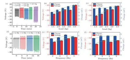
The output voltage is determined by the quantity of CE charge and the speed of contact-separation, but for the same materials, the speed of contact-separation plays a dominant role. Therefore,the output voltage increases with contact frequency (Fig. 4(d)). As shown in Fig. 4(e), the voltage maximum and transferred charge of Al/PTFE generally increase with contact frequency. Besides the speed influence caused by the contact frequency,the increase of CE voltage is caused by the dynamic load, which may be the main reason for the increase of transferred charge quantity. For the Cu/PTFE, the generated charge quantity increases from 4.1 nC to 4.6 nC with contact frequency. Ascribed to the higher hardness and less deformation of Cu than Al, the variations of voltage and charge under different frequencies are smaller for Cu/PTFE(Fig. 4(f)). The voltage even fluctuates due to the dynamic effect, even though it increases with frequency as a whole.The variations of CE voltage and transferred charge quantity of metal/kapton under different contact frequencies are quite similar to those of metal/PTFE (Fig. S5 in supporting information),which demonstrates the aforementioned influences of contact frequency on CE.
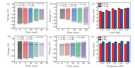
The effects of load and contact frequency on CE are further studied on the surfaces that get to the stable state under different loads or contact frequencies. As shown in Figs.5(a)and 5(b), the Al/PTFE contact systems get to the stable state under loads of 4.0 kg (case 1) and 1.5 kg (case 2), respectively, after which the CE output voltage increases with load(see Fig.S6(a))with no apparent difference between these two conditions. For the transferred charge, the the charge quantity varies from 4.6 nC to 5.7 nC as the load increases after the system has gotten to the stable state under the load of 1.5 kg, while that of the 4.0-kg case increases from 4.9 nC to 5.6 nC, with the charge quantity varying from 1.1 nC to 0.7 nC. As stated previously, the CE process is determined mainly by the creep and deformation of surfaces. Surfaces stabilizing in case 1 creep and deform more than those in case 2. So the transferred charge quantity in case 1 is generally larger than that of case 2 for smaller loads due to the larger real contact area caused by deformation under a larger load.However, the less creeping surfaces in case 2 are more sensitive to load,and hence the transferred charge varying more.Like the effect of load, the output voltage increases as well with the contact frequency for Al/PTFE systems stabilizing under the frequency of 5 Hz(case 3,Fig.5(d))and 2 Hz(case 4,Fig.5(e)).Higher frequency indicates a larger dynamic load for CE, so the maximum of voltage increases with frequency(Fig.S5(b)). The transferred charge quantities seem to maintain at the same level for both cases, rather than to increase with frequency (Fig. 5(f)). Generally, the transferred charge quantities at different frequencies in case 3 are smaller than those of case 4. The surfaces in case 3 stabilize at a higher frequency of 5 Hz, indicating a larger dynamic load that will cause a greater creep effect on the surface,which finally leads to smaller CE transferred charge quantity.
The surface is further characterized by using XPS to investigate the evolution of the surface and reveal the mechanism of charge transfer. Figure 6 shows the XPS results of the Al and Cu surfaces before and after contacting PTFE for 60 min, which indicates the dramatic variations of the peak value for different elements. On the Al surface, the Al 2p and O 1s values drop a lot after contacting the PTFE, while the value of C 1s increases greatly. The analysis of the proportion of elements also indicate Al element decreases from 30.76% to 17.25% , and O element from 46.24% to 27.87%,but C element increases from 23%to 54.88%after contacting the PTFE. Compared with the dramatic decrease of Al 2p on the Al surface, the decrease of Cu 2p on the Cu surface after contacting the PTFE is much small. The O 1s peak value increases,which may indicate the oxidation of the surface. Still,the increase of C 1s can be observed. The variations of proportion of elements before and after contacting the PTFE also demonstrate the changes on the Cu surface (Figs. 6(e) and 6(f)). Tiny changes are also observed on the PTFE surfaces before and after contacting Al or Cu surface(Fig.S7). However,it is not so significant as those after contacting Al or Cu surface, and no unmistakable Al or Cu signal is detected on PTFE surfaces. Therefore,there must be material transfer between the two surfaces during CE besides electron transfer.Moreover, electrons transfer from Al or Cu to the PTFE surface, which changes the surface state of the two contact surfaces. Then the two surfaces interact more actively and consequently cause material to transfer from PTFE to Al or Cu surface, which may inversely enhance the charge transfer at the interface.
Further XPS analysis of metal (Al and Cu) surfaces before and after contacting kapton and PET shows that the increase of element C on the metal surfaces is a common phenomenon(Figs.S8 and S9). The increase in the content of C must result from the breaking of molecular chains on the polymer surface and the transfer of materials at the contact interface in the CE process. The broken chemical bonds can act as the acceptor of electrons during contacting the metal, which is one of the reasons for gradually increasing the transferred charge quantity in the CE process. In brief,there are both material transfer and electron transfer in the process of CE,during which both of the mechanisms will have effects on each other.In the process of CE for polymer, the chemical bond breaks,leading the material to transfer to the metal surface, resulting in the increase of the relative content of C on the metal surface.While the electrons on the metal material surface transfer to the polymer surface. The polymer degradation and evolution of surfaces can slow kinetically in the time frame of the experiment, but the observations in these experiments indicate that the further interfacial degradation can have an influence on the lifetimes of devices where this phenomenon may be utilized.
4. Conclusions
In summary, the CE process is systematically studied,which shows that the voltage and the transferred charge quantity increase gradually with the contact time until they reach a relatively stable state. The variation of charge quantity in the CE process is related to the creep properties of the polymer and the deformation of metal surfaces. A surface consisting of polymer with stronger creep resistance can get to the stable state more quickly. Therefore,the CE performances of different polymer materials vary greatly. The variations of voltage and the generated charge quantity are ranked in the following order: PTFE>kapton>PET. The CE charge charge is related to the electronegativity of constituent elements and the functional groups in the polymer.
Regardless of the change of load or frequency, the CE voltage is determined mainly by the speed of contactseparation. Therefore,the increase of load and frequency will increase the voltage. In general, the CE charge between the metal and the polymer increases with the increase of the load,and the time taken to stabilize is longer for larger loads. With the increase of contact frequency,the CE charge quantity will get to a stable state faster due to the longer time of contact in a certain time,and the contact charge quantity will be larger. As the surface reaches the stable state of the CE process,the CE charge quantity will also increase with load, but the variation is obviously less due to the evolution of surfaces. Contrastingly,the contact frequency has no effect on the CE charge in this condition, though the increase of the frequency will augmenting the maximum of voltage.
The material transfer is observed in CE besides the electron transfer. Electrons transfer from metal to polymer surfaces, which change the surface state of the two contact surfaces. Then the two surfaces interact more actively and consequently cause material transfers from polymer to metal surface, which may inversely enhance the charge transfer at the interface. The study is conducive to our understanding of the fundaments of contact electrification between metal and polymers,and provides insights into the performance of TENG under various conditions,which sheds light on the design and optimization of CE-based energy harvest and self-powered sensing devices.
Acknowledgement
Project supported by the National Natural Science Foundation of China(Grant Nos.52075249,51505217,51435008,and 51705247).
猜你喜欢
杂志排行
Chinese Physics B的其它文章
- Ergodic stationary distribution of a stochastic rumor propagation model with general incidence function
- Most probable transition paths in eutrophicated lake ecosystem under Gaussian white noise and periodic force
- Local sum uncertainty relations for angular momentum operators of bipartite permutation symmetric systems
- Quantum algorithm for neighborhood preserving embedding
- Vortex chains induced by anisotropic spin–orbit coupling and magnetic field in spin-2 Bose–Einstein condensates
- Short-wave infrared continuous-variable quantum key distribution over satellite-to-submarine channels