How to realize an ultrafast electron diffraction experiment with a terahertz pump: A theoretical study
2022-05-16DanWang王丹XuanWang王瑄GuoqianLiao廖国前ZheZhang张喆andYutongLi李玉同
Dan Wang(王丹) Xuan Wang(王瑄) Guoqian Liao(廖国前)Zhe Zhang(张喆) and Yutong Li(李玉同)
1Beijing National Laboratory for Condensed Matter Physics,Institute of Physics,Chinese Academy of Sciences,Beijing 100190,China
2School of Physical Sciences,University of Chinese Academy of Sciences,Beijing 100049,China
3Songshan Lake Materials Laboratory,Dongguan 523808,China
4Collaborative Innovation Center of IFSA,Shanghai Jiao Tong University,Shanghai 200240,China
Keywords: terahertz pump,ultrafast electron diffraction,terahertz-electron interaction
1. Introduction
The rapid development of strong terahertz sources[1—10]opens up new opportunities for controlling and manipulating materials. Particularly, since the spectra of terahertz covers various low-energy excitations such as phonons in lattice,[11]rotations in molecular or hydration bonds in biological systems,[12]there is a great hope that with its electric field now exceeding 1 MV/cm,strong terahertz sources can directly perturb the nuclei degrees of freedom and even induce a structural phase transition,[13,14]free from the mediation of electronic excitations induced by infrared or visible light. Then,the subsequent structural dynamics can be monitored by a typical pump—probe experiment.Among various available probes that can extract the transient response of nuclei, diffraction methods such as ultrafast electron and x-ray diffraction techniques stand out, because they can follow the subtle changes of bond length or lattice constant together with the changes of structural symmetry through samples’ diffraction fingerprints with femtosecond temporal resolution.[15]So far, several terahertz-pump-x-ray-probe studies have been carried out which gain new insights of lattice dynamics.[14,16,17]However,the terahertz-pump-electron-probe studies on this topic are largely missing,[18]although terahertz sources have already been utilized to accelerate[19—28]or manipulate[19,22,23,29—38]electrons with many potential applications.
The main obstacle for combining UED with terahertz sources lies in the fact that the electromagnetic field of the terahertz pump interacts strongly on the electron probe. Thus,if the terahertz pump and electron probe encounter each other before reaching the sample, the electron probe will be deflected preventing it from probing the structural dynamics afterwards. Figure 1 shows such deflection issue schematically.Suppose the incident angle of the electron probe in UED is initially set-up according to Bragg’s law

to form diffraction patterns without terahertz-pumping. Here,dis the lattice constant,θis the diffraction angle,andλ0is the de Broglie wavelength of electrons. Then any pump-induced change indwill lead to a change inθcausing a relative shift in the position of the diffraction peak as Δd/d=Δθ/θaccording to Eq.(1). Meanwhile,the intensity of the diffraction peak may also alter either due to Δθ,[39]or due to other lattice dynamics such as lattice heating.[40]These fine structural changes can be resolved from the subtle differences of diffraction peaks between with and without pumping recorded by UED.However,if the electron probe encounters the terahertz pump before probing the sample as shown in Fig. 1(a), the pre-set incident angle (without pumping) is altered. Accordingly,the diffraction patterns are also altered or even disappear containing no information about lattice dynamics yet. As we will show in details later,such artifact varies dynamically with the probe’s time-delay according to the terahertz-pump,almost impossible to be corrected actively in a pump-probe experiment.And therefore,it must be carefully considered and eliminated when designing a terahertz-pump-electron-probe experiment. On the other hand,if such deflection happens after the sample is probed by the electrons as shown in Fig. 1(b), the diffraction patterns will still shift as a whole,yet the structural information has been recorded. Then, it could be recovered,in principle,even with improved temporal resolution since the terahertz can work as a streak camera.[22,30—33,35,41]
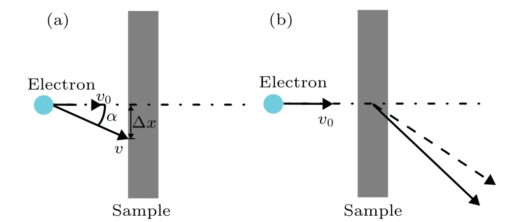
Fig. 1. The electron probe encounters the terahertz pump (a) before the sample, which affects the probe’s pre-set incident angle, and (b) after the sample,which does not.
In this article, we studied the terahertz-induced deflection effect on the electron probe of UED as shown in Fig.1(a)in details. We considered two colinear UED set-ups, namely the observe set-up and reversal set-up, in which the electron probe travels in the same direction as and in the opposite direction to the terahertz-pump,respectively. We found that for 100-keV electrons,no matter the sample is highly reflected or transmitted,significant deflection effect lasts so long that it is very difficult to carry out a pump—probe experiment with the observe set-up. To tackle this issue, we proposed two practical schemes by reshaping the terahertz waveform and by designing a noncolinear set-up. On the other hand, for highly reflected sample, a pump—probe experiment with the reversal set-up is largely not affected by such deflection effect, although the diffraction pattern will be shifted dynamically. It inspires us to use a metal-mesh as the sample holder to screen the terahertz pump for the reversal set-up. We also repeat all the above simulations for 3-MeV electrons. In general,the deflection effect for 3-MeV electrons is much smaller than for 100-keV electrons. With some minor adjustment, a pump—probe experiment can be realized in this case. We hope our study could arise people’s attention to the terahertz—electron interaction,and boost the multidisciplinary researches in both terahertz and UED societies.
2. Methods
Taking into account both the electric and magnetic effects of the terahertz field, the resultant force that acts on a single electron can be written as

in whiche=1.60×10⁻¹⁹C is elementary charge,vrepresents velocity vector of the electron,EandBrepresent electric and magnetic terahertz field vectors,respectively.The acceleration of electron can be calculated as
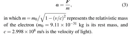
We considered two possible UED set-ups for terahertzpump—electron—probe experiment. In the obverse case as shown in Fig.2(a),the terahertz pump is focused on the sample by an off-axis parabolic mirror (OAP) with a horizontal hole through which the electron beam travels in the same direction as the terahertz pump.On the other hand,in the reverse case as shown in Fig.2(b),the terahertz pump and the electron probe travel collinearly in the opposite direction. The sample is assumed to be perpendicular to the electron beam.
Fig.2. Experimental layout. (a)The obverse set-up, in which the electron moves in the same direction with focused terahertz pulse. (b)The reversal set-up,in which the electron moves in the opposite direction to the focused terahertz pulse.
where “±” takes “+” in the obverse case and “-” in the reverse case. In Eq.(4),Erepresents the terahertz electric field


Fig.3. The terahertz spectrum and waveform for a pump centered at fTHz =0.2 THz with fFWHM =π2/(16ln2)fTHz in panel(a)and in panel(b),respectively,and with fFWHM= fTHz/2 in panels(c)and(d),respectively.
If we substitutet′=(±z/c)-t,then the terahertz waveform used in our simulation can be written as

Since the terahertz beam size(several millimeters even at the focus)is much larger than the electron beam(several hundred microns), we use a single electron initially at (0, 0,-∞) att=-∞to characterize an electron pulse with finite transverse size. SinceEis set alongxaxis in our simulation(Ey=Ez=Bx=Bz=0),the electron accelerationa(x,y,z,t)can be derived according to Eqs.(2)and(3)as
In our simulation the integration is achieved through step by step computing

Table 1. Parameters used in the simulation.
3. Results
3.1. The obverse case
We first consider the case when the terahertz pump completely transmits through the sample(T=100%). The corresponding evolution of deflection angleαand deflection distance Δxas a function of delay-timet0of a 100-keV electron probe is shown in Fig. 4(a). Depending on where the pump and probe encounter each other, their interaction can be divided into three regions as shown in Fig. 4(b). It can be seen that when the two beams overlap close to the sample (region I in Figs. 4(a) and 4(b)), electrons are strongly streaked. The overall time scale of this region is roughly the period of the terahertz pump. Also, in this region, only part of the terahertz waveform contributes onαand Δx, while the other part encounters electrons after the sample, which has no effect onαand Δx. Since the waveform of the terahertz beam starts with a quarter period of negative electric field followed by a half period of positive and another quarter period of negative field,αfirst increases, then decreases and increases again, accordingly. The streaking speed in the quasi-linear range (between the maximum and minimum ofα)is about-3.69×10⁻⁵rad/fs. Meanwhile,Δxalso changes several tenth micrometers. In region II, the two beams meet between the OAP and sample,so that the electron receives the interaction from the whole period of terahertz pulse. Since the terahertz beam is not focused transversely yet,the change ofαstarts to decrease quickly. And between 100 ps and 130 ps,the absolute change ofαis about 2.7157×10⁻⁴rad with an averaged streaking speed about 9.05×10⁻⁹rad/fs. On the other hand, Δxdoes not reduce likeαin this region, because the less focused terahertz beam the probe encounters, the longer distance it must travel to the sample. So, the reduced change inαis balanced by the increased travel distance. Finally, in region III,the two beams meet each other close to OAP,where only a portion of unfocused terahertz waveform encounters the probe. And therefore, a “wrinkle” appears in bothαand Δxjust like in region I,but with opposite variation trend,because the OAP cuts the wavefront with negative electric field first.
Next, we consider the case when the terahertz pump is completely reflected by the sample(T=0%). And the corresponding evolution ofαand Δxis shown in Fig. 4(c). Since the electric field of the reflection beam points to the opposite direction of the original beam (see Fig. 4(d)), the deflection effect is partially cancelled. Also,because the reflection beam focuses tighter than the original beam when encounters the electrons,the deflection effect from the former is larger,leading to a positive value ofαand negative value of Δxin both regions I and II.In region III,electrons mainly encounter the original terahertz beam cut by OAP.So,a wrinkle appears inαand Δxcurves similar as the case of region III in Fig.4(a). In regions IV and V when the delay-time is long,electrons only meet the reflection beam, so the general variation trends of bothαand Δxcurves are just opposite to the ones in regions II and III in Fig.4(a), respectively. Comparing withT=100%case,the reflection of terahertz beam makes the amplitude ofαand Δxless but nonnegligible deflection effect lasts for longer time-scale.
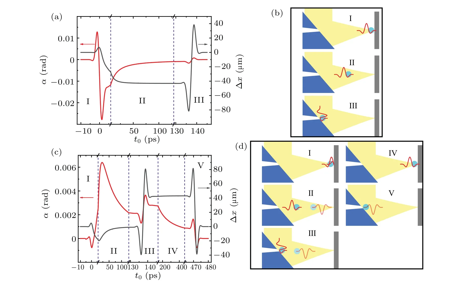
Fig.4. The deflection angle α and deflection distance Δx as a function of the delay-time t of 100-keV electrons in the obverse case when the sample transmittance T is(a)100%and(c)0%. The red solid line represents α,while the gray solid line represents Δx. (b)and(d): schematic diagrams for regions marked in panels(a)and(c).
The continuous change inαand Δxmakes the above observe set-up unfavorable for a pump—probe experiment to study the transient structural dynamics in time domain. According to the two-beam dynamical diffraction theory under the assumption of no absorption, the intensity of Bragg peak can be described as[39,42]

whereIrepresents the Bragg peak intensity,dsis the thickness of the sample,ξgis the extinction distance, andsis the excitation error that characterizes the deviation from the exact Bragg condition.[39]Since the electron probe always has certain transverse deviation,so the overall intensity of the Bragg peak should be considered as an integration through a range ofscovered by the deviation angle of the electron probe.Considering the initial energy spread of the photoelectrons is about 0.5 eV, the transverse deviation angle of the final 100-keV electron beam is about 0.002 rad, and this number decreases to about 0.001 rad for MeV electron beam because its longitudinal speed is doubled.
To quantitatively determine how the intensity of Bragg peaks changes according toαis beyond the scope of this paper(see the appendix for more details),so here we use a simple criterion:if the change ofαis comparable to the deviation angle of the electron probe(in this case,0.002 rad),the intensity of the Bragg peaks are assumed to be attenuated to a degree that it couldn’t reflect the real lattice structural dynamics any longer. Judged by this criterion,region I in both Figs.4(a)and 4(c)cannot be used for a pump—probe experiment becauseαchanges drastically. However, region I is usually not counted in a pump—probe experiment, because the terahertz pump on the sample is not completed yet. Accordingly, the minimum delay-time of the electron probe should be at least one pulse width of the terahertz pump, roughly the same time scale of region I.And such streaking effect could be used for checking the alignment and synchronization between the electron and terahertz beam. Moving into region II, it can be seen that its early stage still could not be used for such experiments until about 50 ps, when the changing rate ofαbecomes much smaller. Even at this stage, the overall change ofαbetween 50 ps and 130 ps is still about 0.002 rad,comparable to the deviation angle of the electron beam. So,unless one can further divide this time range into several small sections and re-align the electron beam one section by one section, it is still difficult for a pump—probe experiment. All the other regions in Figs.4(a)and 4(c)are also hard to be used for a pump—probe experiment due to the existence of the wrinkles inαand Δxcurves. So, we may conclude that for the observe set-up, a pump—probe experiment could only be carried out whent0is longer than 150 ps forT=10%case,more than 10 periods of terahertz oscillation,and even longer forT=0%case when it reaches about 500 ps.
To reduce the deflection from the terahertz pump in the observe set-up,here we propose two experimental schemes.
The first one is to adjust the waveform of the terahertz field to make the contribution from the positive and negative fields cancel each other. For example,if we reduce the bandwidth of the terahertz beam and make the wave package contain several circles of oscillations, then the deflection from it will be significantly reduced. Figures 5(a)and 5(b) show the evolution ofαand Δxcaused by a terahertz beam that has roughly two circles of oscillations as shown in Fig. 3(d). It can be seen that for bothT=100%andT=0%cases,region II can be used for pump—probe experiment in which the amplitude ofαis much smaller than the deviation angle of the 100-keV electron beam. Another approach to obtain multi-cycle terahertz waveforms is to use higher frequency terahertz pulse.As shown in Fig.5(c),the higher frequency the terahertz pump has,the less it deflects the probe. For example,with the same electric field strength,the magnitude ofαis reduced by a factor of 592 forfTHz=10 THz compared tofTHz=0.2 THz. Another possible method to achieve the same goal is to change the carrier-envelope offset phase(CEP)of the terahertz pump to balance the positive and negative field strengths. For example,if the carrier-envelope offset phase of the terahertz pump shown in Fig.3(b)is shifted aboutπ/4,then the magnitude of positive and negative fields will be close to each other leading to a cancelation inαcurve. Now terahertz sources with different carrier-envelope offset phases and frequencies are available through different generation methods.[43—45]
Fig.5. The deflection angle α and deflection distance Δx as a function of delay-time t0 for 100-keV electrons in obverse case when the waveform of terahertz field shown in Fig.3(d)is used with(a)T =100%and(b)T =0%. (c)The maximum of α and Δx as a function of fTHz with the waveform of terahertz field shown in Fig.3(b)and T =100%.

Fig.6. Noncolinear scheme in the obverse case: (a)the experiment layout with(b)a highlight of the sample location. The corresponding deflection angle α and deflection distance Δx as a function of delay-time t0 for 100-keV electrons in obverse case with(c)T =100%and(d)T =0%. (e)Schematic diagram for a tilted sample. (f)The corresponding α and Δx as a function of t0 for 100-keV electrons in the tilting sample scheme with T =0%and γ =π/4.
To further increase the time window for pump—probe experiment,we come up with a noncolinear scheme(Fig.6(a)),in which the OAP is tilted towards the sample so that the pump and probe travels noncolinearly. In this respect,the spacial overlap of the two beams is only achieved very close to the sample location (mm scale), and therefore, the deflection from the pump attenuated very quickly after about 10 ps. Figures 6(c) and 6(d) show the evolution ofαand Δxin such noncolinear scheme forT=100%andT=0%,respectively.In the simulation,the tilting angle of terahertz beam according to electron beam (γ) is set to beπ/4, while other parameters are the same as used in Fig. 4. It can be seen thatαreturns to zero about 10 ps and 20 ps forT=100%andT=0%,respectively. Also,the maximal amplitude of Δxis only several micrometers. Comparing Fig.6 with Fig.4,the advantage of noncollinear scheme on collinear one is clearly seen.
One potential issue for such scheme is that the projection of the electric field on thezdirection will accelerate or decelerate electrons dynamically so that both the central energy and the energy spread of the probe will change as a function oft0.However, if we only use the time domain whenαis close to zero, then, such effect is negligible. Another issue for such scheme is that it will introduce the velocity and the geometrical mismatch[46]that worsen the overall temporal resolution as shown in Fig.6(b),because now the sample is not pumped and probed simultaneously alongxaxis. The overall temporal resolution could be estimated by[46]

whereτpumpandτproberepresent the longitudinal durations of the terahertz pulse and electron beam,respectively.τjitterrepresents the timing jitter between the pump and the probe. Andτmisis the temporal smear due to the velocity and the geometric mismatch[46]as we just mentioned,which can be estimated by

whereleis electron beam size,respectively.Assumingτpump=1 ps,τprobe=200 fs,τjitter=0 ps,ds=100 nm,le=100 μm,and even usingγ=π/2,we getτtotal=3.1 ps,not significantly lengthened if comparing with the time scale of region I. But asγincreases, the pumping area also increases as 1/cos(γ)which decreases the pumping fluence,another factor one must weight when designing the experiment.
We also considered the possibility to tilt the sample(see Fig. 6(e)) rather than the pump. The difference between this scheme and the noncolinear scheme is that the former only reduces the spacial overlapping between the reflected pump beam and the probe. Since the original pump beam also deflects the electron probe significantly,this scheme does not extend the usable time window too much. Figure 6(f)shows the simulation result for this case withγ=π/4 andT=100%. It can be seen that in the first 20 ps(roughly region I in Fig.4),the deflection effect does reduce significantly if compared with the noncolinear scheme. However, it lasts for a longer time scale similar as the region II in Fig. 4(a) due to the contribution from the original pump beam. Also,the overall temporal resolution is reduced by the velocity and the geometric mismatch that can be estimated by

As a result, it is not an effective approach for 100-keV electrons, But, as we will show later, it is very helpful for UED with 3-MeV electrons.
3.2. The reversal case
In the reversal case (Fig. 2(b)), the electron and the terahertz pulses travel in the opposite direction (γ=π) so that they only meet each other once. Figure 7(a)shows the evolution curves ofαand ΔxforT=100%,and figure 7(c)shows the two curves forT=0% and 1%, respectively. Here, we ignored the tinyτmis(less than 1 fs) in the simulation. ForT=100%, the interaction between pump and probe is similar to the situation described in Fig. 4(a) for the initial two regions,and both two curves also look very similar in the two cases. On the other hand,forT=0%,bothαand Δxare not affected by the terahertz beam because the pump and probe encounter each other after the sample and it does not affect the pre-set diffraction angle and probed position. ForT=1%,the deflection is just 1% ofT=100% case confirming that only the transmitted beam affectsα.

Fig.7. The deflection angle α and deflection distance Δx as a function of delay-time t0 for 100-keV electrons in reversal case with(a)T =100%and(c)T =0%(horizontal lines)and 1%(solid curves). (b)and(d)Schematic diagrams for regions marked in panels(a)and(c). (e)Schematic diagram that shows how to screen the terahertz pump by a mesh in the reversal case.
Compared with the obverse set-up, the reversal set-up withT=0% seems to be more situatable for a pump—probe experiment. To enhance the reflection of terahertz beam in this case, we proposed to use metal grid to hold the sample as shown in Fig. 7(e). So long as the wavelength of the terahertz beam is much larger than the pitch size of the mesh,terahertz wave will be screened out to achieveT=0%. In fact,these metal grids are widely used for transmission electron microscopy.The drawback for the reversal set-up is that OAP can block the diffracted electron beam. To solve this problem,one may apply the noncolinear scheme (see Fig. 6(a)) but with a negative titling angle.
3.3. Using higher energy electrons
According to Eqs. (6) and (7), bothvx(t) andqx(t) decreases asvincreases due to the relativistic effect, thus bothαand Δxdecreases around one order in magnitude for 3-MeV electrons if compared with 100-keV ones as shown in Fig. 8(also see Figs.4 and 7 for comparison). ForT=100%of the obverse set-up,the evolution ofαcurve mimics the waveform of terahertz beam(see Fig.3(b)),which is different from all the curves for 100-keV electrons. This is becausevnow is very close to the speed of light so that the electron interacts with terahertz mostly in pace. On the contrary, for lower energy(100 keV for example) electrons, terahertz beam surpasses electrons from behind so that a large portion of its waveform deflects electrons.At a first glance,this seems like a disadvantage because it prevents the contributions from the negative and positive field in one terahertz circle to cancel each other.However, such disadvantage is compensated by the cancelation between the forces from the electric and magnetic field,as the latter one increases withvto a comparable magnitude to the former (see Eq. (6)). So, comparing theαcurve in Fig. 8(a) with Fig. 4(a), its magnitude is largely reduced by a factor of 16. Also, as shown in Fig. 8(d), the maximum ofαdecreases when the energy of electron increases. Since the velocity of MeV electrons are close to the speed of light,αvery quickly decreases to zero around one period of terahertz,because longer than this time-delay,the terahertz beam is always ahead of electrons and they do not encounter each other any longer, another advantage for using MeV electrons in a terahertz—pump—electron—probe experiment. ForT=0%in obverse set-up, considerable amount ofα(in the order of 0.01 rad) persists to several tenth picoseconds due to the reflection of the terahertz pump(in this case,the forces from the electric and magnetic field add up) which impedes a pump—probe experiment. One possible method to solve this issue is to tilt the sample instead of terahertz pump to reduce the deflection from the reflected terahertz pump only.But it will sacrifice certain temporal resolution due to the geometrical mismatch(see Eq.(12)).
In the reversal case,bothαand Δxcurves resemble those for 100-keV electrons(see Figs.7(a)and 7(c))but with almost one order smaller in magnitude,which make 3-MeV electrons better than 100-keV electrons for such a pump—probe experiment. But it still faces the blocking issue of diffracted electrons by the OAP,which could be improved by using the noncolinear pumping scheme(see Fig.7(a)).
So far, we only consider the deflection effect of the terahertz pump on the intensity of Bragg peaks. In many UED experiments, the transient change in lattice constants is also monitored from the position shift of the Bragg peaks as a function of time,characterized by the relative peak position change Δθ/θ. Then,it is more proper to useα/θto characterize the deflection effect on Bragg peak positions. Figure 8(d) shows how the maximum ofα/θchanges as a function of electron energy in the obverse case. And we can see that the deflection effect on Bragg peak positions starts to decrease rapidly when the energy of electrons enters MeV range,making MeV UED a better choice for such study,although the much smaller Bragg angles in MeV UEDs may bring other challenges in resolving Bragg peaks.

Fig.8. The deflection angle α and deflection distance Δx as a function of delay-time t0 for 3-MeV electrons in obverse case with(a)T =100%and(b)T =0%and in reversal case with(c)T =100%and 1%. (d)The maximum of α and deflection angle divided by diffraction angle α/θ for electrons with different energies for sample with d=5 °A and T =100%in the obversed case.
3.4. The deflection from terahertz-induced non-propagating field
Up to now, we only considered a very ideal case, where the sample is assumed to be perfectly flat and is perpendicular to the incident electron beam, so that the influence of the sample on terahertz beam is simplified by the reflection and negligible absorption. But in the real situation, the dielectric constant, the geometry, and the local structure of the sample and the sample mount can strongly attenuate the localEandBfields. If such near-field is evanescent (immediately disappears after the terahertz pump and roughly the same timescale as region I), we will show that its effect on the UED experiment is not so important. First,we argue that the effective interaction length alongzaxis between such evanescent near-field and electrons is much less than the wavelength of the pump beam. This argument comes from several superresolution techniques such as near-field scanning optical microscopy, where a change in the local field in the order of one tenth of the pump’s wavelength can be resolved. On the other hand, the effective interaction length between electrons and terahertz beam is around the Rayleigh length (in the order of the terahertz wavelength under the condition that the F-number of the OAP is around 1),within which the terahertz beam is tightly focused. As a result, unless the near-field is strongly enhanced such as in a terahertz resonator (then, it is not evanescent), its deflection effect is negligible if compared with that from the original and reflected beam. We think this is probably the case for a typical TEM sample,where the length scale of its roughness or the wrinkles on it are both much smaller than the terahertz wavelength, causing random scattering of light only. It is also true for our proposal where we use a metal grid as the sample holder as shown in Fig.7(e),where the terahertz wave is completely screened(reflected).
However, if such terahertz-induced field is not evanescent, such as the dipole field due to the plasma,[47]the resonant field in a split-ring[48]and so on,the amplitude of such local field can be very large and its effective interaction length on electrons can be also significantly extended. As a result,their deflection effect dominates. In fact, ultrafast electron has already been used as a probe to map such transient field in several cases.[48—51]But such sample conditions should be avoided when designing a UED experiment.
Finally,we want to give only a qualitative analysis on how such enhanced local field affects 3-MeV UED,for the cancellation betweenEandBis only important for such high energy electrons. We assume that the field does not propagate in pace with the electrons. Otherwise, the deflection effect will enhance a factor of one hundred without the cancellation betweenEandB. Now, the interaction between terahertz pulse and electron is very similar as for the low energy electron cases but the deflection force reduces a factor of 5.74 due to the relativistic mass of 3-MeV electrons. Given the field strength same as the terahertz pump and an effective interaction length of the Rayleigh length,from Figs.4(a)and 4(c),the maximal change ofαcan be estimated to be about 0.001 rad. This is also consistent with Fig.8(b),where the maximal change ofαis doubled to 0.002 rad,becauseEandBare added in the reflected terahertz beam. Based on these estimations,if the field can be localized in the length scale of at least one order less than the Rayleigh length,it will not affect the diffraction patterns significantly. However,if the strength of the local field is enhanced,then it must be confined further to reduce the effective interaction length on electrons.
4. Conclusions
In this article, we theoretically studied the terahertzinduced deflection effect on the electron probe of UED and how it affects the incident angle and the probe location on the sample. In general, when the electron energy reaches MeV range,the terahertz-induced deflection becomes small enough to realize a pump—probe experiment. However, for electron probe with its energy around 100 keV or less,such experiment is much harder to design,although this energy range is widely used in electron microscopy, and is more suitable for some fragile samples like 2D materials. Particularly,in the observe set-up, both original pump beam and its reflection from the sample deflects the electron probe significantly, while in the reverse set-up, only the original beam contributes. We introduced several schemes to tackle this issue. This first scheme is to reshape the waveform of the terahertz pump, so that the deflection from its positive and negative portion may cancel each other. Since the available tools to manipulate the optical parameters of a terahertz pulse such as its frequency,bandwidth and CEP are still sparce,the applicability of this scheme mostly depends on how the terahertz pump is generated. The other scheme is to use a noncolinear pump—probe set-up to reduce the spacial overlap between the pump and probe. As a result,the time-window suitable for a pump—probe experiment extends significantly. However,due to the velocity and the geometric mismatch,the overall temporal resolution and the energy stability of the electron probe is worsened, and the field amplitude of the terahertz pump is reduced. For the reverse set-up, we proposed to use a metal grid as the sample holder to screen the terahertz pump in order to eliminate the transmitted pump. We hope our study could arise people’s attention to the terahertz—electron interaction, and blend the merits of terahertz and UED techniques.
Acknowledgements
Project supported by the National Natural Science Foundation of China (Grant Nos. 11774409, 11827807, and 92050106). This work is supported by the Synergic Extreme Condition User Facility.
Appendix A
In this appendix,we would like to show howαaffects the intensity of Bragg peaks.The reason we use absolute angle instead of relative angle is that we mainly consider the intensity change of the Bragg peak due to the change of,which depends on the product ofξgands. Let us assume that the UED is initially perfectly aligned to obtain maximal diffraction intensity withξgs=0. Then, according to Eq.(9), the diffraction intensity will drop significantly whenξgs~1 due toα.

Here,ξgcan be expressed as[42]and for the sameg(the same plane index),F(θ) ∝f(θ),where
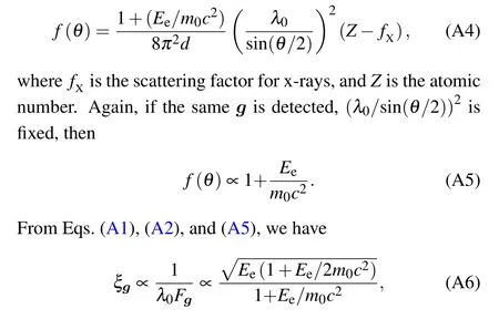
which is plotted as a function of electron energy as shown in Fig. A1. It can be seen thatξgincreases about a factor of 1.8 when the electron energy increases from 100 keV to MeV.This means that the diffraction intensity for MeV UED drops larger than 100-keV UED,given the sames. However,it does not depend onθ.Then, from Eqs. (A6) and (A8), we may conclude thatξgsonly depends onα.

Fig.A1. The ξg as a function of electron energy Ee.
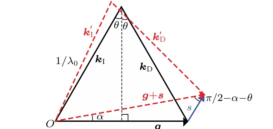
Fig. A2. Schematic diagrams for the relation between s and α. kI is the wave vector of the incidence electron, and kD is the wave vector of the diffracted electron. k′I and k′D represent the wave vectors deflected by α due to the terahertz pump.

In this article,we used a simple criterion:if the change ofαis comparable to the deviation angle of the electron probe,the intensity of the Bragg peaks is assumed to be attenuated to a degree that it could not reflect the real lattice structural dynamics any longer. The deviation angle for different ultrafast electron sources depends on many factors, which is hard to quantify. To make a fair comparison, here, we just simply assume that the initial energy spread of the photoelectrons(0.5 eV)is fixed. Since the velocity of MeV electrons is twice of 100-keV ones, the resultant deviation angle for MeV electrons is only half of 100 keV which balanced the factor of 1.8 inξg. So, our compassion between UEDs with different energy electrons based on this simple criterion is justified.
猜你喜欢
杂志排行

Chinese Physics B的其它文章
- A nonlocal Boussinesq equation: Multiple-soliton solutions and symmetry analysis
- Correlation and trust mechanism-based rumor propagation model in complex social networks
- Gauss quadrature based finite temperature Lanczos method
- Experimental realization of quantum controlled teleportation of arbitrary two-qubit state via a five-qubit entangled state
- Self-error-rejecting multipartite entanglement purification for electron systems assisted by quantum-dot spins in optical microcavities
- Pseudospin symmetric solutions of the Dirac equation with the modified Rosen–Morse potential using Nikiforov–Uvarov method and supersymmetric quantum mechanics approach