High-fidelity resonant tunneling passage in three-waveguide system
2022-02-24RuiQiongMa马瑞琼JianShi时坚LinLiu刘琳MengLiang梁猛ZuoLiangDuan段作梁WeiGao高伟andJunDong董军
Rui-Qiong Ma(马瑞琼), Jian Shi(时坚), Lin Liu(刘琳), Meng Liang(梁猛),Zuo-Liang Duan(段作梁), Wei Gao(高伟), and Jun Dong(董军)
School of Electronic Engineering,Xi’an University of Posts and Telecommunications,Xi’an 710121,China
An N-stage three-waveguide system is proposed to improve the robustness and the fidelity of the resonant tunneling passage.The analytic solutions to the tunneling dynamics at the output are derived.When the number of subsystems increases, tunneling efficiency approaches to 100% in a large range and resonant tunneling is robust against variations in the phase mismatch and peak tunneling rate.
Keywords: amplitude control,resonant tunneling passage,robustness
1.Introduction
High population efficiency and inherent robustness are important for some quantum gates used in quantum information processing(QIP).For a reliable QIP,the population transfer error needs to be reduced below 10−4in order to achieve very high fidelity.
Adiabatic passage(AP)is a popular technique for manipulating the state of a quantum system.It was used first in nuclear magnetic resonance technique.[1]Then,various AP techniques have been presented, such as Stark-chirped rapid adiabatic passage,[2,3]superadiabatic passage,[4]and stimulated Raman adiabatic passage(STIRAP),[5–7]to name a few.Generally, the population transfer efficiencies of all AP schemes are close to(but less than)unity.The fidelity of 90%–95% suffices the most traditional applications.However,such a fidelity is insufficient for QIP.Therefore several optimized schemes,including Davis–Dykhne–Pechukas(DDP)method,[8–10]parallel adiabatic passage(PLAP)technique,[11,12]piecewise adiabatic passage(PAP)technique,[13,14]shortcuts to adiabaticity(STA),[15,16]non-Hermitian shortcut to adiabatic passage,[17]composite adiabatic passage(CAP),[18,19]composite STIRAP scheme,[20,21]etc.,have been proposed to improve the fidelity and robustness of AP.
Similarities between adiabatic passage in atomic system and molecular system, and the tunneling dynamics in waveguides systems have attracted a great deal of attention in theoretical and experimental studies.[22]The optimized schemes for quantum systems are robust against small variations in experimental parameters and hence some schemes have been used to design the waveguide coupler.For example, to improve the tunneling efficiency of waveguides systems, STIRAP scheme,[5]DDP technique,[23]STA scheme,[24–26]and non-Hermitian shortcut to AP scheme[27]are extended to the designing of waveguides couplers.It is noted that the optimized techniques mentioned above are all adiabatic.During the population transfer passage,the system follows one or two adiabatic states.[28–30]In this paper,the tunneling dynamics in each subsystem is based on non-eigenstate,and the tunneling passage is nonadiabatic.[31]
The STIRAP scheme was used to design the waveguide couplers with high tunneling efficiency.[5]No matter whether the amplitudes and widths of the tunneling rates or the distance between two peak tunneling rates changes, the nonadiabatic tunneling exists and the fidelity of the STIRAP is near the benchmark 10−4of QIP.[23]Then non-Hermitian shortcut to AP scheme,an optimization scheme based on STIRAP,introduces a non-Hermitian term to cancel nonadiabatic tunneling.The fidelity of AP is increased, and tunneling distance is shortened.Like the scenario in the STIRAP technique, the adiabatic condition also requires a large tunneling rate area and hence the length of coupler is not shortened.However,the channel width is constant,which makes it easy to fabricate.[27]The DDP optimized technique suppresses the tunneling point by choosing an appropriate tunneling rate distribution.Although the fidelity is further improved,the length of coupler is still long.[23]The STA technique,based on transitionless quantum driving algorithm,introduces an unfeasible relative phase and has been exploited to shorten the length of waveguides coupler.[25]The total length of coupler is about 1/6 of the one designed by traditional schemes,however the disadvantage of STA scheme is that the channel width changes continuously along the coupler, hence such a structure is difficult for practical implementations and stays mainly in the stage of theoretical research.[24–26]We use the amplitude control method,unlike the phase control scheme,to improve the tunneling efficiency and fidelity of the resonant tunneling passage.By adjusting the ratio between the tunneling rate amplitudes of each three-waveguide subsystem, the fidelity of the resonant passage is reduced below the benchmark 10−4without changing the channel width.This structure is easy to fabricate and can be exploited to design robust quantum gates.For instance,the diffused structure with the same channel width has been demonstrated in theory and experiment.[32,33]The STA technique and the STIRAP technique have been used to design single-qubit gates, such as Not- and Hadamard gates.[23,34]Owing to the robustness of the resonant tunneling passage,a train ofN-stage three-waveguide systems has the potential to design a high-fidelity Hadamard gate, which is one of the fundamental gates in QIP.
Traditional PAP technique usually needs additional phases.Shapiroet al.have developed a particular PAP scheme without considering the additional phases.They used a series of femtosecond pulses turned suddenly on and off repeatedly to execute a robust adiabatic passage.The amplitudes of the femtosecond pulses coincide with those of the counterintuitive pulses in the STIRAP.[13]Rangelov and Vitanov have extended this technique to a three-state quantum system.They used a series ofNpairs of coincident pulses to fulfill complete population transfer,and the envelope of coincident pump and Stokes pulses also match the counterintuitive pulses used in the STIRAP.[35]Inspired by these two schemes,we design anN-stage three-waveguide couplers with the same channel width to improve the fidelity of resonant tunneling transfer.The rest of this paper is organized as follows.In Section 2 the propagator for a single three-waveguide subsystem is presented.In Section 3 are shown the analytic solutions to beam power at the output and the maximum transient beam power trapped in central waveguide for anN-stage three-waveguide system.In Section 4 the fractional tunneling passage is discussed.In Section 5 are presented the similarities and differences between this resonant scheme and the STIRAP and also analyzed the fidelity and robustness of the resonant passage.
2.Single three-waveguide subsystem
The light amplitudesCi(z)(i=L,C,R)of a single threewaveguide subsystem are governed by the corresponding STIRAP-like equation[29,32]

where C(z)=[CL(z),CC(z),CR(z)]Tare the amplitudes of the fundamental modes,L,C,and R are the subscripts that represent the left, middle, and right waveguide, respectively.The Hamiltonian of a single waveguide subsystem takes the form
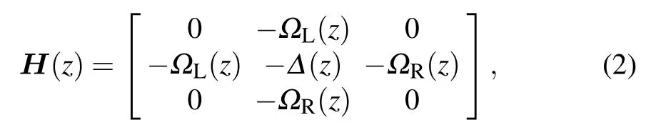
where Δ(z)=βC−βn,(n=L,R)is the phase mismatch,βL,βC,and βRare the propagation constants of three channels.In a single three-waveguide subsystem,the tunneling rates ΩL(z)and ΩR(z)sharing the identical distance functionf(z)change with the distance between waveguides L ↔C and R ↔C,and expressed as
On the dark–bright basis, the STIRAP-like equation (1) is solved analytically and simply.[36]The corresponding propagator for the nonadiabatic tunneling passage in a single threewaveguide system reads[31]

where the mixing angle is defined by θ =arctan(ΩL/ΩR)=AL/AR, andA=is the root mean square (RMS) tunneling rate area.In the area integral,zidenotes the initial position.Using the propagator (4), we can obtain the exact analytic solution to the tunneling dynamics for a three-waveguide system.
A single three-waveguide system discussed in Section 5 includes three 8-mm-long coplanar waveguides as shown in Fig.1(a).We choose the Gaussian distributions ΩL(z) =and ΩR(z) =,where θ1=π/8 and Ω0=√=2 mm is the tunneling rate width,zc=4 mm is the central position of waveguides coupler.In Fig.1(a),

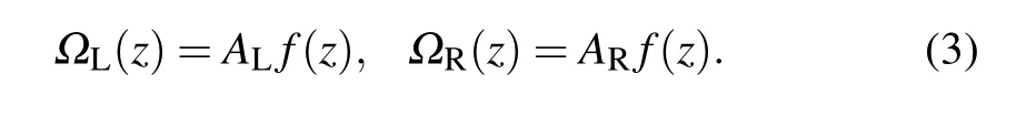
are the distances between two outer waveguides and the central waveguide, respectively.[31]Ω′=1.789 mm−1, γ =0.7759 µm−1, anda0= 9 µm are determined experimentally.[32]The refractive index profilenw(x,y) of each channel fabricated by ion exchange technique[37]is expressed as follows(see Fig.1(b)):
whereDx=4.6µm andDy=4.1µm are the diffusion lengths alongxandydirections respectively,2w=5µm is the channel width,ns= 1.522 is the substrate refractive index, and Δn=0.014 is the peak index change.These waveguide structure parameters are selected according to Ref.[32].

Fig.1.(a)Coupler structure and(b)refractive index distribution nw(x,y)of each channel for single three-waveguide system.
3.Complete tunneling transfer in a threewaveguide system
In anN-stage three-waveguide system (Nis the number of three-waveguide subsystems), each subsystem has mixing angle θiand RMS tunneling rate areaAi.In analogy with the beam propagation in cascaded slab system,[38]the total propagator reads Next we consider the two cases.

Case 1C(zi)=[1,0,0]T,light is introduced from waveguide L,the beam power evolves in three waveguides in which the corresponding power expressions are given by

Case 2C(zi)=[0,0,1]T,light is introduced from waveguide R, the beam power expressions Scorresponding to the three channels are presented as follows:

For each of three waveguide subsystems, the tunneling rate takes the same form

where the two parameters Ω0andBare the same as those used in Section 2.The central positionzciand the mixing angle θifor each of three waveguide subsystems are variable parameters.Particularly, the parameter θiis responsible for beam splitting ratio.
3.1.An example: two-stage three-waveguide system
ForN-stage waveguides system,we first consider the simplest coupler systemN=2.Using Eqs.(7)and(8),we obtain the exact solutions to the whole tunneling dynamics for the two cases.
Case 1
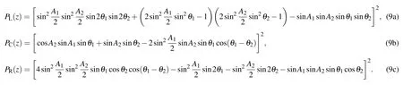
Case 2

where

θ1=π/8,θ2=3π/8,zc1=4 mm,andzc2=12 mm.
The exact analytic solutions Eqs.(9) and (10) for the whole tunneling dynamics are shown in Fig.2.The maximum beam power in central waveguide decreases when light is injected into waveguide L (Fig.2(b)), this suppression is due to the destructive interference of the consecutive coherent tunneling.As opposed to the previous case,the maximum beam power in central waveguide increases when light is injected into the waveguide R(Fig.2(c)),This enhancement results from the constructive interference.
For anN-stage waveguide system (N≥3), the analytic solutions to the whole tunneling dynamics are more cumbersome than those to Eqs.(9) and (10), but the exact analytic solutions to the beam power at the output port and the maximum beam power in central channel have simple forms.

Fig.2.(a)Tunneling rates of two-stage three-waveguide system for complete tunneling transfer scheme and((b),(c))evolutions of beam power trapped in waveguides L,C,and R versus propagation distance z.
3.2.Exact analytic solution to beam power at output ports
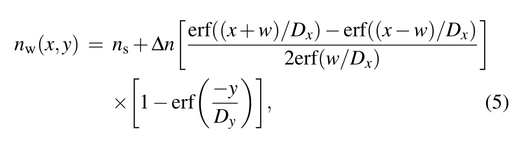
For a single three-waveguide subsystem,the beam power in channelCvanishes at the output whenAi=π.[31]If we consider anN-stage three-waveguide system and substituteAi=π into Eqs.(4) and (6)–(8), the analytic solutions to the final beam power at the output port read as follows.
For Case 1

For Case 2

where 2n+1 and 2n∈N.The values of mixing angle θifor different three-waveguide subsystems cannot be the same,because the identical angle only increases the total length of the coupler while the tunneling passage in a three-waveguide system is only a simple repetition of the tunneling passage in a subsystem.Solving Eqs.(11) and (12) in the two cases,we find that there are many schemes to choose the mixing angle θi, the simplest angle relation takes the form θi=(2i−1)π/4N, where (i=1,2,3,...,N).For Case 1, the final beam power at the output portsPL-fnial=PCfnial=0 andPR-fnial=1,and for Case 2,PL-fnial=1,PC-fnial=PRfnial=0.
Equation (11c) is identical to Eq.(12a), indicating that complete tunneling transfer is also achieved in the Case 2.Tunneling efficiency reaches 100%, provided tunneling rate area for each of three waveguide subsystemsAi= π.In a three-state Λ atomic system, the Case 2 should be avoided,because intermediate-state excited in the Case 2 is a radiative state.Decay from the atomic system through intermediatestate results in the transfer loss and the decrease of the efficiency of population transfer.This is a serious defect for preparing coherent quantum state.In a three-waveguide system, beam power also flows into waveguide C in the Case 2,but it will not leak from waveguide C,and the tunneling efficiency still reaches 100%.Therefore the Case 2 can still be used to prepare some useful optical quantum states.
3.3.Exact analytic solution to maximum beam power in central channel
The angle relation θi=(2i−1)π/4Nproduces the different values of maximum beam power in central waveguide in different cases as shown in Fig.2.To obtain analytic solution for maximum beam power in the middle of the coupler,first, we analyze a two-stage waveguide system, and then extend the results to anN-stage system.From Fig.2, we find that the maximum value ofPC(z) is small when light is injected into waveguide L.On the contrary,the maximum value ofPC(z)increases if light is injected into waveguide R.Light power in the central waveguide reaches the maxima at the positionszc1=4 mm andzc2=12 mm.To obtain the exact analytic solution to beam power in central waveguide, the simplest scheme is to chooseA1=π/2 andA2=0.According to Fig.3, we obtain the maximal value=sin2(π/8)for Case 1 and=cos2(π/8) for Case 2.For theNstage waveguides system, the maximum beam power values are readily obtained from Eqs.(4)and(6)–(8)as follows.
For Case 1

For Case 2

For the Case 1,equation(13)demonstrates that the maximum beam power in the central waveguide decreases as 1/N2when the number of three-waveguide subsystems,N, turns larger.For the Case 2,whereas,equation(14)indicates that the maximum beam power in central waveguide approaches to unity whenNtends to infinity.These results are in accordance with those of Fig.2.

Fig.3.Tunneling rate area of each subsystem in a two-stage waveguides system versus propagation distance z,where Ai(z)=(i=1,2).
4.Fractional tunneling transfer in a threewaveguide system
Arbitrary fractional tunneling ratio between two outer channels is controlled by changing the mixing angle θi.When θi=(2i−1)π/8N, the analytic solutions (11a), (11c), (12a),and (12c) indicate that final beam power=1/2 for Cases 1 and 2,the equal tunneling transfer is achieved and this device can be used as a beam splitter.For Case 1,the analytic solution to maximum beam power in central waveguide reads=sin2(π/8N).AsNtends to approach to infinity,≈(π/8N)2.For equal tunneling scheme,we find that the maximum value of the beam power in central channel is a quarter of the one for the complete tunneling scheme.
5.Discussion
In waveguide optics, the STA technique introduces an unfeasible relative phase.[25]To satisfy this phase condition,the width of waveguide needs to be changed continuously.It is difficult to connect different couplers due to the different waveguide widths.However, the present scheme controls the amplitude ratio of the tunneling rate for each of the three waveguide subsystems.The distance between two adjacent waveguides determines the tunneling rate.The total tunneling rate distribution is governed by the curvature radius of the curved waveguide.It is easier to control a fixed curvature radius than the variable width of each channel.The present scheme is feasible in practical application.
The main differences between the STIRAP and the resonant tunneling passage in the three-waveguide system are discussed as follows.First, the STIRAP in a waveguide system uses counterintuitive tunneling rate distribution.When light is injected into waveguide L, the ΩRprecedes ΩL.Stimulated Raman passage is adiabatic due to the appropriate counterintuitive tunneling rate.In the present technique, two tunneling rates share the same modulation functionf(z), only the amplitudes (ARandAL) of two tunneling rates are different.Such tunneling rates leads the beam power to depend on the tunneling rate areaAas shown in Eqs.(4)and(6)–(8), therefore the tunneling passage is resonant.Second, the STIRAP is based on dark state which is the eigenstate of Hamiltonian of waveguides system.However, the tunneling transfer discussed in this paper depends on the non-eigenstate analyzed in Ref.[31].In quantum mechanics, if a system evolves on its eigenstates,such an evolution is adiabatic.Hence the tunneling passage in each of three waveguide subsystems is nonadiabatic.Third, in the STIRAP, beam power tunnels into waveguide R if light is injected into waveguide L,only a tiny amount of energy remains in waveguide C.Here,the resonant tunneling passage occurs with the aid of waveguide C.When light is injected into waveguide L, equation (13) shows the maximum beam powerin channel C decreases asNturns bigger, whenN→∞,→0.When light is introduced from waveguide R,equation(14)indicates the maximum beam powerin waveguide C increases asNincreases,whenN→∞,→1.The beam power tunnels into the target channel through waveguide C.In the resonant scheme, waveguide C is an important auxiliary channel and there is no energy loss in channel C.However,in the STIRAP scheme,tiny beam power stays in channel C,this energy loss which is due to the nonadiabatic tunneling reduces the tunneling efficiency.By carefully choosing the counterintuitive tunneling rate,the energy loss can be reduced.
The final beam power depends only on RMS tunneling rate area according to Eqs.(4) and (6)–(8), therefore different tunneling rate distributions are also practicable.Before designing anN-stage waveguides system, first,we need to carefully determine the total length of onestage three-waveguide subsystem.To achieve 100% tunneling efficiency, only one condition need to be met, namely the integralAi==π, whereziandzfare the positions of input port and output port, respectively.We analyze the length of a single waveguides subsystem designed under two tunneling rate schemes: one is Gaussian shape ΩL(z)=,ΩR(z)=and the other is hyperbolicsecant shape ΩL(z) = (1/B)sinθisech[(z−zc)/B], ΩR(z) =(1/B)cosθisech[(z−zc)/B].For a single three-waveguide subsystem, we choose initial positionzi= 0 mm, final positionzf= 8 mm, the central positionzc= 4 mm, and the parameterB=1 mm that dominates the widths of tunneling rates.The numerical integration for Gaussian shape readsA1= 3.14159, therefore total length 8 mm can satisfy the area conditionA1= π and the tunneling efficiency reaches 100%.Whereas, using the same calculation parameters, the result of the numerical integration for hyperbolic-secant shape isA1=3.06834.Compared with the standard value π,the relative error is about 2.33%.For the hyperbolic-secant shape,if we choosezc=14 mm,zf=28 mm,the RMS tunneling rate areaA1=3.14159,then the area conditionA1=π is met until the total length reaches 28 mm.Under the same width parameter B, the length of coupler designed by hyperbolic-secant shape is longer than the one designed by Gaussian shape.Different tunneling rates lead to different device lengths,and we need to carefully determine the length of coupler in order to guarantee 100% tunneling efficiency.Theoretically,the longer length leads to the better integral area and hence the higher tunneling efficiency,but we need to choose an optimal length from the perspective of device integration.
The envelope functions of the tunneling rates for complete tunneling transfer take the formAL= Ω0sinθiandAR=Ω0cosθi, where the mixing angle θi=(2i−1)π/4N,(i=1,2,...,N).In the limitN≫1,the variation of adjacent angle Δθ =θi+1−θiis so small that θibecomes nearly continuous, the initial angle θ1=π/4N→0 and the final angle θN=(2N−1)π/4N→π/2.When light is injected initially into waveguide L, the resonant tunneling passage resembles the optimized STIRAP in the three-waveguide system.[23]The analyses are described as follows.First, the STIRAP in a waveguide system is realized by using counterintuitive tunneling rate distributions, here, the envelope functionAR(z)dominates overAL(z) at the early stage whileAL(z) dominates in the end, these two envelope functions correspond to counterintuitive tunneling rates as shown in Figs.4(a) and 4(b).Second, the maximum beam power in central waveguide decreases with the increase of the number of the subsystems.“More subsystems” means that the total coupling area is very large and corresponds to the global adiabatic condition in STIRAP.[5]Figures 4(c)and 4(d)indicate that the resonant tunneling transferring from waveguide L to R is similar to adiabatic passage due to the envelope modulation functions.For the equal tunneling passage, more waveguide subsystems reduce the maximum beam power in central channel as shown in Figs.4(e)and 4(f).

Fig.4.((a), (b)) Tunneling rates and ((c), (d)) evolutions of beam power trapped in waveguides L, C, and R versus propagation distance z for Nstage waveguide system.Left column: N=6,right column: N=9.Light is injected into left channel.Second row: complete tunneling transfer.Third row: equal tunneling transfer.
We note that the analytic solutions to Eqs.(11) and (12)are satisfied only under the conditionAi=π.Figure 5 shows the curves of final beam powerPRtrapped in waveguide Rversusphase mismatch Δβ and peak tunneling rate Ω0for someN-stage three-waveguide systems (N= 1, 3, 15, and 30).Light is injected into waveguide L.The first row of Fig.5 shows the curve ofPRversusphase mismatch and tunneling rate.ForN=1,PRreaches a maximum value only at the peak tunneling rate Ω0=√(B=1 mm)as shown by Eq.(11).ForN=15 andN=30, the corresponding values ofPRtend to unity in a large region.To indicate the benchmark value 10−4,the values ofPRrange from 0.9990 to 1.The second row shows the curve ofPRversusphase mismatch when Ω0=√.The third row displays the curve ofPRversustunneling rate when phase mismatch Δβ =0.

Fig.5.Curves of final beam power PR of N-stage three-waveguide system versus phase mismatch Δβ and peak tunneling rate Ω0.

Fig.6.Fidelity 1−PR of N-stage three-waveguide system versus peak tunneling rate Ω0 when phase mismatch Δβ =0.Horizontal dotted line indicates the benchmark level 10−4 in√ QIP.Resonant tunneling passage occurs at the horizontal coordinate Ω0=,where B=1 mm.
The present scheme is a resonant technique, therefore we discuss the fidelity and robustness near the resonant point Ω0=√.Figure 6 shows the fidelity of anN-stage threewaveguide systemversuspeak tunneling rate.The fidelity is defined as 1 −PR.The results show that the fidelity is improved asNincreases.At the resonant tunneling point Ω0=√, the analytic solution (11) indicatesPR=1 when light is injected into waveguide L, hence 1 −PR= 0 and log10(1−PR) →−∞.Theoretically, as the peak tunneling rate approaches to the resonant point Ω0=√, the fidelity on a logarithmic scale should tend to negative infinity.In Figs.6 and 7, because the step size of numerical calculation is 0.0001,the fidelity on a logarithmic scale only tends to −8 whenN=30.Near the resonant point Ω0=√, figure 6 indicates that the fidelity can be kept below the benchmark level 10−4asNincreases and the resonant passage is robust against variation of peak tunneling rate in the region from Ω0=1.5 to Ω0=2.The peak tunneling rate depends on the incident wavelength and the distance between two adjacent waveguides,and the variation of temperature changes this distance, therefore the resonant passage is robust with respect to variations of wavelength and temperature.
Figure 7 indicates that whenN= 30 the fidelity is reduced below 10−4in the region from β = −0.4 mm−1to β =0.4 mm−1.It indicates that the resonant passage is robust against variation in the phase mismatch.The phase mismatch is dependent on the waveguide width and hence the ambient temperature.Figures 6 and 7 show that the resonant tunneling passage is robust against variations of temperature and incident wavelength asNincreases.For a single threewaveguide systemN=1, the fidelity is below 10−4only at the point Ω0=due to the resonant tunneling transfer.AsNincreases,the envelope of the tunneling rate coincides with the counterintuitive distribution used in STIRAP and the total tunneling rate area becomes larger,the resonant passage in anN-stage three-waveguide system is similar to that in the STIRAP,therefore fidelity and robustness are both improved in a large region.

Fig.7.Fidelity 1−PR versus phase mismatch Δβ when peak tunneling rate Ω0 ≈1.7725.

and assumingV(x,y,z)=≈ns−n(x,y,z)for the triple-well potential,we realize the equal light splitting with a 15-stage three-waveguide system as shown in Fig.8,where= λ/2π, λ = 980 nm is the incident wavelength.We designn(x,y,z) =nw(x+aiL(z),y)+nw(x,y)+nw(x−aiR(z),y) for the refractive index distribution, with subscriptidenoting thei-stage waveguide subsystem.The distances

for each of three waveguide subsystems vary with propagation distancez.For equal tunneling transfer θi=(2i−1)π/8N,other calculation parametersns,a0, γ,B,nw(x,y), and Ω′have been introduced in Section 2.The |ψ|2predicted by a numerical solution of Eq.(15) describes the light transfer in anN-stage three-waveguide system.The simulated results are in good agreement with the exact analytic solutions from Eq.(11).
For a 15-stage three-waveguide system, Ω1=1.967 mm−1and Ω2=1.578 m−1are the boundaries of the high-fidelity region as shown in Fig.6.The(Ω1−Ω0)/Ω0×100%≈11% and(Ω0−Ω2)/Ω0×100%≈11% are the maximum permissible errors between the boundary and the peak tunneling rate.When fabricating this three-waveguide structure, 0.24-µm deviation between the centers of two adjacent waveguides is allowed.This is beneficial to coupler fabrication.Considering Fig.6 and the length of waveguides coupler,N=15 is recommended for practical application.
The classical light field evolving in a 15-stage threewaveguide system is shown in Fig.8.Whereas, this coupler can also come into effect at a single-photon level.For the equal tunneling passage, when a single-photon is introduced into waveguide L (R), it encodes a logical 0 (1).At the output of the waveguide system,the initial state|L〉is transformed into a coherent superposition state (|L〉−|R〉)/2 = (|0〉−|1〉)/2 which corresponds to the Hadamard gate.

Fig.8.Beam intensity evolution|ψ(x,0,z)|2 in a 15-stage three-waveguide system for equal tunneling transfer,with white solid lines denoting waveguides L,C,and R.
6.Conclusions and perspectives
Arbitrary splitting ratio of beam power between two outer waveguides is realized by anN-stage three-waveguide system.In each three-waveguide subsystem,the tunneling transfer is a resonant passage.In the limitN≫1,the envelopes of tunneling rates coincide with the counterintuitive scheme used in the STIRAP, the resonant tunneling passage resembles the STIRAP.The scheme discussed in this paper connects the resonant tunneling passage with the STIRAP.In atomic physics, resonant excitation is dependent on exact pulse areas, and its robustness is sensitive to the variation of amplitude and duration of the laser field.However,the results show that the resonant tunneling passage in anN-stage three-waveguide system is robust with respect to variation of peak tunneling rate and phase mismatch,and hence the temperature and incident wavelength.The robustness and fidelity of the resonant tunneling passage can be improved by increasing the number of three-waveguide subsystems.Compared with the phase control technique, the present technique is an amplitude control method.By using the structure parameters designed in Ref.[31], this threewaveguide system can be easily realized.Owing to the high fidelity and robustness, the scheme introduced in this paper has the potential in designing one- and two-photon quantum gates.[34,40]
Acknowledgement
Project supported by the Natural Science Basic Research Plan in Shaanxi Province,China(Grant No.2018JM6064).
猜你喜欢
杂志排行

Chinese Physics B的其它文章
- High sensitivity plasmonic temperature sensor based on a side-polished photonic crystal fiber
- Digital synthesis of programmable photonic integrated circuits
- Non-Rayleigh photon statistics of superbunching pseudothermal light
- Refractive index sensing of double Fano resonance excited by nano-cube array coupled with multilayer all-dielectric film
- A novel polarization converter based on the band-stop frequency selective surface
- Effects of pulse energy ratios on plasma characteristics of dual-pulse fiber-optic laser-induced breakdown spectroscopy