Research on active arc-ignition technology as a possible residual-energy-release strategy in electromagnetic rail launch
2021-08-05XiyuanCAI蔡喜元SaiTAN谭赛JunyongLU鲁军勇XiaoZHANG张晓andYunGUO郭赟
Xiyuan CAI (蔡喜元), Sai TAN (谭赛), Junyong LU (鲁军勇),Xiao ZHANG (张晓) and Yun GUO (郭赟)
National Key Laboratory of Science and Technology on Vessel Integrated Power System,Naval University of Engineering, Wuhan 430033, People’s Republic of China
Abstract In order to solve the problem of the original residual energy release strategy being unsuitable for high-energy and fast-firing electromagnetic rail launch, this work has explored the applicability of active arc-ignition technology(AAT).The results obtained from the comparison of launching experiments show that AAT has no influence on the acceleration of the armature and is capable of quickly releasing the residual energy.Based on the theory of magnetohydrodynamics, this work has also made numerical simulation of the muzzle arc, analyzed the influence of AAT on the muzzle arc flow field, electromagnetic (EM) field and temperature field, and evaluated the performance of AAT according to the projectile initial disturbance, the EM impact on guidance devices and the rail ablation.The results show that AAT is now one of the most practicable strategies for residual energy release.
Keywords: muzzle arc, initial disturbance, guidance device, arc ablation, backflow
1.Introduction
During the electromagnetic rail launch (EMRL), the energy remaining in the launch system is more than a quarter or even a half of the exit kinetic energy after the armature leaves the bore[1], and it needs to be released.However, the energy level of EMRL is continuously increased to 32 MJ, even 64 MJ, and the speed of continuous firing is up to six shots per minute[2,3].How does one release the residual energy but not affect the launch safety? Firing accuracy and service life of the launcher is one of the key points in the design of high energy level and fast firing rate electromagnetic (EM) rail launchers.
The main criteria for judging whether a residual energy release strategy is good or not are as follows: (1) the release speed of residual energy; (2) the impact of residual energy release on the acceleration of the projectile in the chamber;(3)the impact on the initial disturbance of the projectile; (4) the electromagnetic impact on the guidance devices; and(5) the ablation of the rails.
At present, one of the strategies for releasing residual energy is the arc suppression technology [4–7].When the projectile is accelerated in bore, the arc suppression impedance has a shunt effect on the rail current [7], thus reducing the driving force of the projectile.Because of the high energy Joule heat, the arc suppression device must meet the high requirements for temperature resistance and recovery ability.Another strategy is the passive arc-ignition technology [8].This method does not affect the acceleration of the projectile due to the fact that the arc can quickly release a large amount of residual energy and the air medium has strong capacity of recovery, but it has a seriously ablative effect on the rails,thereby affecting the service life of the launcher.The above strategies are not suitable for high-energy and fast continuous-firing EM rail launchers.
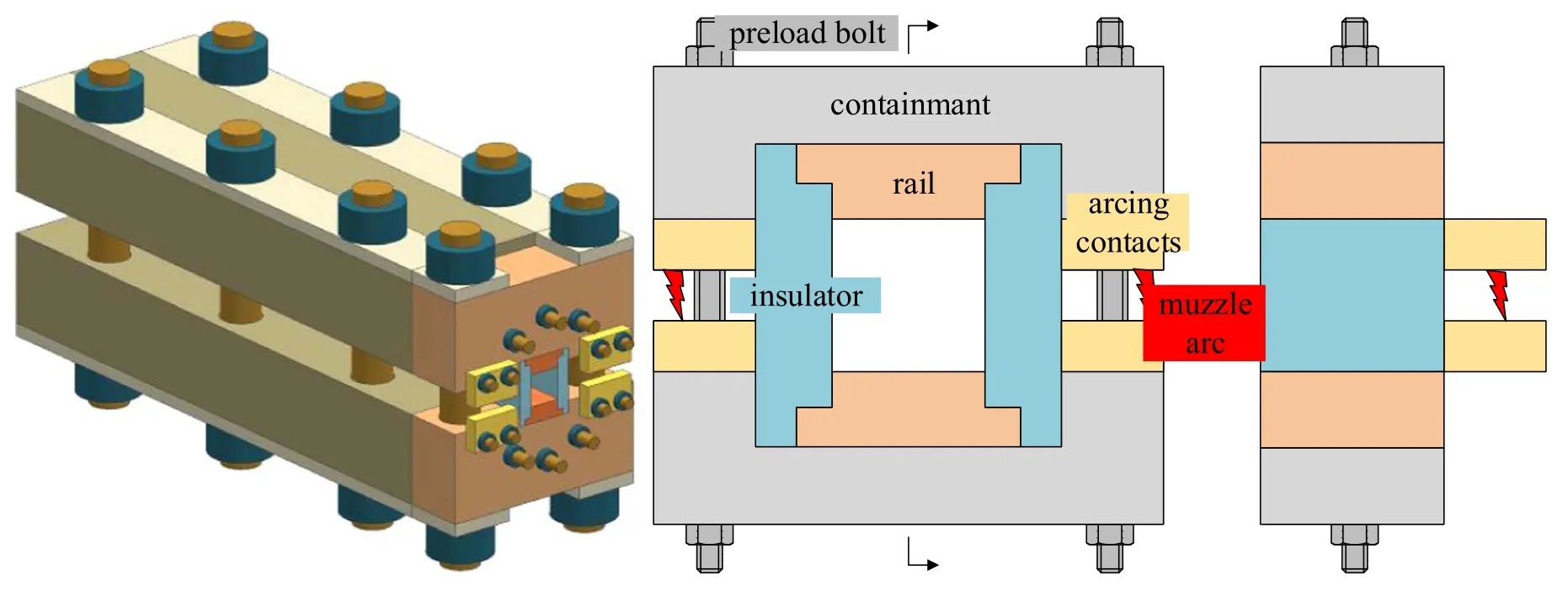
Figure 1.Schematic diagram of the launcher and the AID.
Active arc-ignition technology (AAT) is a new one for residual energy release.The arc-ignition device (AID) connected in parallel with the rails at the muzzle end releases the residual energy in the form of arc.The metal vapor generated by friction and wear of the aluminum armature in the bore enters the arcing gap and reduces the breakdown strength.Shortly after the armature leaves the bore, the muzzle overvoltage breaks through the gap between the arcing contacts,so that the arc between the armature and the rails will rapidly transfer to the AID.AAT is not used for suppressing the arc—a medium for rapid energy release,but for introducing it into the low-cost and replaceable AID.
The influence of AAT on the rate of residual energy release and the acceleration of the projectile remains to be examined.What is worth noting is that the influence of AAT on the initial disturbance of the projectile mainly depends on the distribution of the pressure and the velocity of the muzzle arc, the electromagnetic impact caused by AAT on guidance device is determined by the distribution of the EM field, and the ablation caused by AAT to the trajectory is related to the temperature and airflow velocity.Therefore,it is necessary to study the influence of AAT on the launching process as well as the flow field, EM field and temperature field of the muzzle arc.
In EMRL experiment, the observation of muzzle arc tends to be affected by the radiation of thermal plasma,especially the characteristics of arc flow field are difficult to obtain.Weimeret al[9] used an EM rail launcher with an emission energy level of 12 MJ and a peak current of 1.5 MA as an object of experiment.It is found that a stream of highintensity light, smoke, flame front and luminescent particles flows from the muzzle back to the chamber,with the backflow temperature in the range of 2400–4000 K, and the alkali metals, AlO and CuO existing in the gas.
The increase of the computing capability by computer leads to the continuous progress in the numerical simulation of arc plasma.Using the magnetohydrodynamics (MHD)model of arc, it is possible to give a good description of the characteristics of the distribution of arc temperature field,EM field and flow field [10].Gaoet al[11] conducted a simulation study on the muzzle arc, but the muzzle arc root in their model only exists between the rails, and the current is only about 200 A, which is much lower than the magnitude of current 100 kA of the EMRL when AAT is adopted.This case is quite different from the muzzle arc produced in the use of AAT.The muzzle arc behavior needs to be further studied.
This paper has described the current characteristics of the EM rail launcher in experiment when AAT is adopted and not, investigated the influence of AAT on the release rate of residual energy and the acceleration of the projectile and simulated the muzzle arc.According to the characteristics of muzzle arc, an MHD model has been established, and the finite volume method is adopted for solution.The model can be used to analyze the flow field, EM field and temperature field of the muzzle arc, and to evaluate the influence of AAT on the initial disturbance of the projectile, the EM impact of the guidance device and the rail ablation.
2.Experiment
An EM rail launcher with the caliber of 30 mm×30 mm and an AID,as shown in figure 1,has been designed.The AID is mainly composed of two pairs of arcing contacts and two copper connection boards, and the arcing contacts are connected with the rails via the connection board.After the armature leaves the bore, the current will be transferred from the rails to the arcing contacts, and the arc between the armature and the rails will be switched to the arcing gap.Two groups of comparative launching experiments are carried out respectively with and without the AID.Rogowski coils are used to measure the currents of the breech and the arcing contacts.
Figure 2 shows the currents of the breech, the AID and the armature during the launching.It can be seen that the breech current is the same when the AID is used or not.The discharge characteristics of the power supply are not affected.Before the armature leaves the bore,there is no current in the device.Attout, the total current in the device rapidly rises from zero to the magnitude of the breech current.Aftertout,both the currents are basically the same.This shows that(1)in the acceleration process of the armature,the AID which is in a dormant state, does not affect the driving force of the armature; (2) at the moment of the armature leaving the bore, the device is quickly activated and receives all the current in the rail to ensure the safe disconnection between the armature and the rails;and(3)after the armature comes out of the bore,the device continues to work to finish releasing the residual energy in a short time.
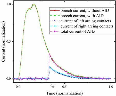
Figure 2.Current curves in experiment.
3.Calculation model
3.1.Hypotheses
As the physical and chemical processes in the muzzle arc of an EM rail launcher are too complex for simulation calculation, it is necessary to simplify the physical process by introducing some reasonable hypotheses.The specific hypotheses are as follows:
• The arc plasma is considered to be in the local thermodynamic equilibrium (LTE) state.
• Ignoring the interaction between the arc and the electrode as well as the electrode sheath,considering the air area at the muzzle as the calculation domain.
3.2.Governing equations
MHD basic equations include mass conservation,momentum conservation,energy conservation,electric field and magnetic field equations.All these equations are unified in the steady form of the Patankar equation:

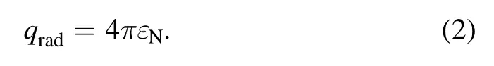
where Φ is the variable to be solved,ΓΦis the diffusion term,andSΦis the source term.The variables and parameters of the MHD equations are listed in table 1.Among them,P,Hand V are respectively the plasma pressure, specific enthalpy and velocity vector;u,vandware the velocity components inx,yandzdirections, respectively;Ax,AyandAzare the magnetic vector potential components;Jx,JyandJzare the current density components;Bx,By,Bzare the magnetic field strength components; ρ,Cp, λ, μ and σ are respectively the plasma density, specific heat at constant pressure, thermal conductivity and viscosity;kbis Boltzmann constant,eis the electron charge, μ0is the permeability;qradis the radiation source term, which is related to the radiation model.
The net emission coefficient εNis used to describe the radiation heat loss of plasma per unit volume, which is regarded as the source term of energy conservation equation,namely
The realizablek-ε model is used to describe the turbulent flow state of muzzle arc.The related parameters and expressions can be obtained from [12] and [13].
The temperature and the pressure near the wall are the highest and the gradient is large.Therefore,the enhanced wall function method is used for treatment.
3.3.Geometry and mesh
The geometry and calculation domain is shown in figure 3.According to the symmetry, a quarter of the air area is taken for the calculation model, in which the in-bore length is 1000 mm,and the radius and length of the air area outside the bore are both 1000 mm.The bolts are neglected.The cuboid is the arcing contact and L-type geometry is half of the armature.According to the features of the geometrical model,the computational domain is divided by the multi-block structural mesh.In order to increase the convergence of the calculation model and the calculation accuracy, the core area is super-refined.According to the requirements of the selected turbulence model and the adjacent-wall method on they+value, repeated trial calculations as well as grid adjustment are conducted and finally they+ value is about 1.They+value is within five,near the insulator wall in the breech end.Considering that the Reynolds number is small and far away from the muzzle end in this place,they+value is considered to be acceptable.The grids with the quality of 0.85–0.90 and 0.90–0.95 account for 0.032% and 6.379% respectively, and the quality of the other grids is above 0.95.The orthogonality of the mesh is greater than 36 degrees,and finally the number of grids is up to 10 million.
3.4.Plasma properties
The aluminum vapor tends to affect the physical properties of plasma medium in the AID.In this paper, the proportion of aluminum and air in the muzzle arc medium are assumed to be 10% and 90%, respectively.Murphy and others [14–19]offered the data,such as thermodynamic properties,transport coefficients and net emission coefficients of Al-air plasma,in the temperature range of 300–50000 K and in the pressure range of 0.01–20 MPa.Plasma properties are related to temperature and pressure.The binary three-point interpolation is adopted to obtain the physical parameters of plasma under the condition of specific temperature and pressure.

Table 1.MHD basic equations.
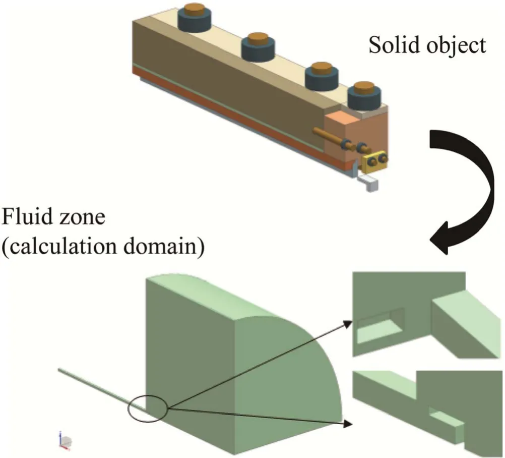
Figure 3.Calculation domain.
3.5.Boundary conditions
Simonyan’s and Kats’studies[20]show that,under the action of plasma, the maximum temperature on the surface of the electrode is close to the boiling point of electrode material.Based on that, the surface temperature of the rail, armature and arcing contact is set as the corresponding material boiling point (2500 K).In experiment, the insulation material was found to be hardly ablated, so it could be treated as the adiabatic wall [21].The outlet pressure is 101.325 kPa and the temperature is 300 K.
After the armature leaves the bore,the arcing contacts on the single side each share half of the rail current.The current is distributed on the interface between the arcing contact and the arcing gap.The current is distributed parabolically.The potential of the armature surface is set to be zero.The potential and magnetic vector components of the outlet are zero,and the magnetic field on the wall is calculated by Biot–Savart law.
4.Results and analysis
The equations mentioned above are solved by the adapted commercial code Fluent, which is based on the finite volume method.For convenience, the forward direction of the armature is defined as thexaxis, and the launcher end is the plane ofx=0.The horizontal direction is set asyaxis, and the symmetry of left and right is the plane ofy=0.The vertical direction is the forward direction of thezaxis.

Figure 4.Airflow rate distribution of the muzzle area.
4.1.Flow field distribution
Figure 4 shows the flow rate distribution at the muzzle area with and without AAT.When AAT is not adopted, the airflow outside the chamber rushes to the end of the rails and dashes upon the wall,thereby forming a complex turbulence.A part of airflow is emitted in the forward direction of the armature, and another part flows back to the inner chamber.The high-velocity region of the muzzle arc plasma is near the end of the rails, and the velocity is up to 8400 m s−1.When AAT is adopted, the airflow above the arc contacts will flow to the arcing gap.It will emit after it is offset in the arcing gap and the airflow moving to the plane ofy=0 will flow out along the vertical center of the launcher.The high velocity region of the muzzle arc plasma is in the arcing gap, and its magnitude will decrease to 5700 m s−1.The velocity of the airflow near the armature and rail end will drop down to 300 m s−1.
Figure 5 shows the distribution of pressure in the muzzle area with and without AAT.When AAT is not used, the maximum pressure is 282 kPa and the pressure difference is 214 kPa,which appear near the muzzle end of the rails.When AAT is adopted,the maximum pressure and pressure gradient in the muzzle area will be shown in the arcing gap.The maximum pressure is 245 kPa and the pressure difference is 161 kPa.Furthermore, the pressure at the armature and rail end is uniform, being very close to the atmosphere.
Airflow is the main reason that the initial disturbance of the projectile is affected by the muzzle arc.The use of AAT can lead to a decrease in the airflow velocity, turbulence,pressure and pressure difference in the muzzle area,especially around the armature, which will be beneficial to the stability of the projectile and reduce its initial disturbance, thereby improving the firing accuracy.
4.2.EM field distribution
Figures 6 and 7 show the distributions of EM field with and without AAT.When AAT is not applied,the EM field of the muzzle arc is mainly concentrated near the armature and rail end,with the peak current density up to 300 MA m−2and the magnitude of the magnetic field up to 0.67 T.When AAT is used,the muzzle arc is transferred to the AID.The maximum current density of the arcing gap is 230 MA m−2and the peak magnetic field is 0.41 T.The current near the armature is greatly reduced to about 0.2 MA m−2, and the magnetic field drops down to about 0.03 T.
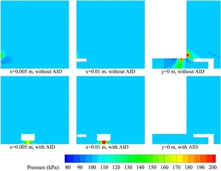
Figure 5.Pressure distribution of the muzzle area.
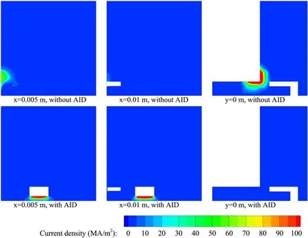
Figure 6.Current distribution of the muzzle area.
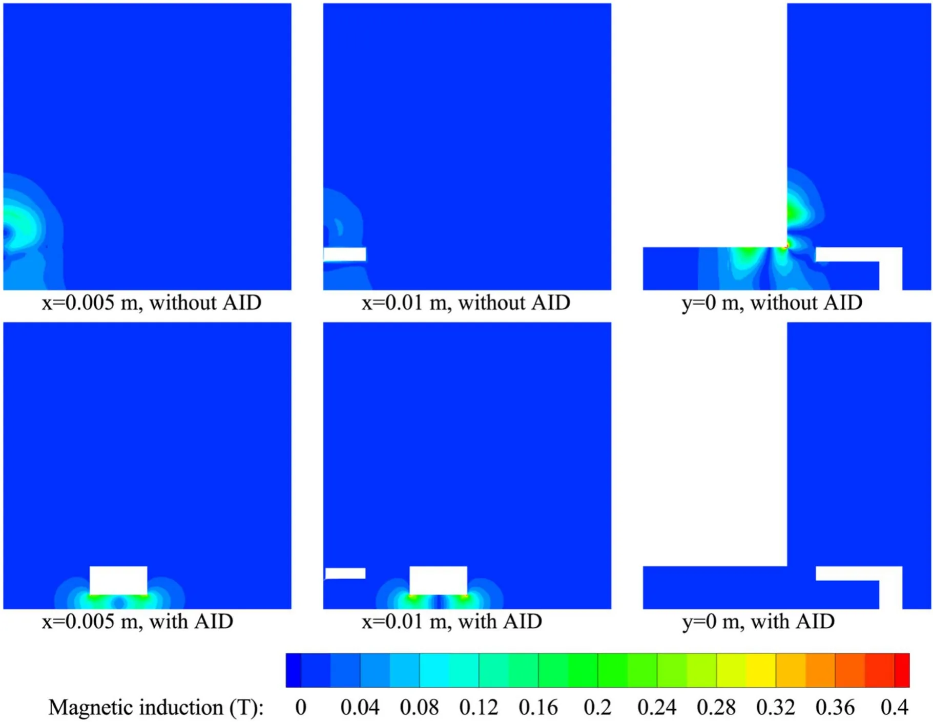
Figure 7.Magnetic distribution of the muzzle area.
The AID has the ability to shunt the current, transfer the muzzle arc.When AAT is not adopted, the current flows directly from one rail to the other, and the current is more concentrated.But if it is applied, each of the two pairs of arcing contacts will share only a half of the residual current.As a result, the arc current on the single side will be greatly reduced.In addition, the arcing contacts are distributed on both sides of the rail,so the muzzle arc is enlarged.The AID expands the muzzle arc from two aspects of current and space,and reduces the EM field in the muzzle area,especially near the armature.Therefore, the application of AAT can reduce the EM impact on the internal guidance device of the projectile to prevent it from losing its vitality.
4.3.Temperature distribution
Figure 8 shows the distribution of temperature in the muzzle area with and without AAT.When AAT is not used, the muzzle arc concentrates between the armature and the rails,with less expansion in the direction perpendicular to the armature movement.In the direction of the armature movement, the muzzle arc covers the armature when expanding forward and forms a backflow in the bore when expanding backwards, with its maximum temperature being 28000 K.When AAT is applied, the muzzle arc is concentrated in the arcing gap.Its maximum temperature is 25000 K, while the temperature of the backflow at the end of the rails and in the chamber is greatly reduced to 6000 K or so.
The application of AAT can alleviate the ablation of the rails in the muzzle end.When subjected to the high-temperature arc plasma, the rail surface will undergo evaporation erosion and droplet splashing, which lead to a loss of materials.Because of the arc transfer of the AID,the arc column is shifted from between the rails to the arcing gap.Besides, the shunting effect of the AID can reduce the current and the temperature of single-sided arc, so the heat flux to the rail surface will be greatly reduced.According to the analysis in section 4.1, the adoption of AAT makes it possible to reduce the airflow velocity around the rails,and to weaken the impact of the thermal flow on the rail surface as well.Thus, the alleviation of the rail ablation will help prolong the service life of the device.
5.Conclusions
Because the original strategy of residual energy release is not suitable for high-energy and rapid EMRL, this paper proposed a new approach named AAT and investigated its performance.Through experiments and numerical calculations,AAT is proved to be applicable for dealing with the residual energy release, the acceleration of the armature, the initial disturbance of the projectile, the EM impact on the guidance devices, and the ablation of rail materials.
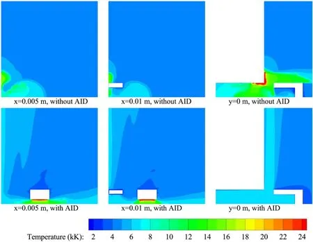
Figure 8.Temperature distribution of the muzzle area.
AAT has the following characteristics: when the armature accelerates in the bore, AID is in a dormant state; when the armature leaves the bore, the device quickly transfers the current, without affecting the power discharge and the armature acceleration.What is more, the residual energy can be released shortly after the armature leaves the bore.
AAT has the ability to transfer the muzzle arc.It reduces the airflow velocity and pressure in the area around the rail end and armature, distributes the pressure more uniformly,weakens the EM field,and decreases the temperature greatly.As a result,it is possible to decrease the initial disturbance of the projectile,weaken the EM impact on the guidance device inside the projectile and alleviate the rail ablation, thereby improving the performance and firing accuracy of the launcher and prolonging the service life of the rail.In short,AAT is now one of the most practicable strategies of releasing the residual energy for high-energy, and rapid EMRL.
Acknowledgments
This work was supported in part by National Natural Science Foundation of China (Nos.51522706, 51877214 and 51607187) and in part by the National Basic Research Program of China (973 Program) (No.613262).
杂志排行

Plasma Science and Technology的其它文章
- Two-point model analysis of SOL plasma in EAST
- Line identification of boron and nitrogen emissions in extreme- and vacuumultraviolet wavelength ranges in the impurity powder dropping experiments of the Large Helical Device and its application to spectroscopic diagnostics
- Landau damping of twisted waves in Cairns distribution with anisotropic temperature
- Effects of magnetic field on electron power absorption in helicon fluid simulation
- Dependence of plasma structure and propagation on microwave amplitude and frequency during breakdown of atmospheric pressure air
- Machine learning application to predict the electron temperature on the J-TEXT tokamak