镍基金属有机框架及其衍生物在电催化析氧反应中的研究进展
2021-07-10徐冰妍张应皮业灿邵琪黄小青
徐冰妍,张应,皮业灿,邵琪,黄小青,*
1 厦门大学化学化工学院,福建 厦门 361005
2 苏州大学材料与化学化工学部,江苏 苏州 215123
1 Introduction
With the rapid development of modern society, energy and environmental issues are becoming more and more prominent.To address these pressing challenges, it is highly essential to develop efficient and clean renewable energy to replace the traditional fossil fuels1–3. As one of the most ideal and cleanest energy carriers, hydrogen has attracted extensive attentions of researchers. Electrochemical water splitting is considered as a promising technology for massive hydrogen production of the future, which can be combined with various sustainable energy resources, such as solar energy, tide energy and wind energy4.Water splitting can be presented as two half reactions: hydrogen evolution reaction (HER) at the cathode and oxygen evolution reaction (OER) at the anode. Among them, OER is considered to be the main bottleneck of water splitting due to its complex multi electron/proton transfer steps with slow kinetic process5.Currently, noble metal such as IrO2, Ir/C and RuO2are considered as the most active OER catalysts, while their scarcity and high cost have greatly restricted their wide application. In addition to reducing the load of noble metals, it is an ideal solution to replace precious metals with transition metals. In alkaline environments, compounds of transition metals (Fe, Co,Ni) have been extensively studied due to their variable oxidation states and the existence of 3delectrons, and have achieved good catalytic activity in OER6,7.
In recent years, metal organic frameworks (MOFs), also known as porous coordination polymers, have attracted more and more attention in the field of electrocatalysis due to their unique porous structure, highly dispersed metal composition and superhigh specific surface areas8,9. Among them, articles on nickel-based MOFs (Ni-MOFs) and their derivatives in OER have doubled every year since 2016. Its advantages can be divided into the following points: (1) When Ni-MOFs are directly used as catalysts, there are abundant open channels in its structure. And nickel active sites with good redox property are evenly distributed (even exposed) in the framework10. (2) When different metal components were introduced into Ni-MOFs,especially the other iron group elements (Fe and Co), a synergistic effect was formed to improve the catalytic performance11–14. (3) There are abundant organic ligands in Ni-MOFs, which can form carbon-based skeleton by high temperature reduction8. And the metal also helps to promote the graphitization of carbon matrix, so as to improve the conductivity, prevent the aggregation and corrosion of transition metals, and increase the overall support strength15. (4) In addition, Ni-MOF, as a precursor, can be oxidized, phosphated or vulcanized to obtain Ni-MOFs derivatives with various components16. In particular, the unique structure and morphology of Ni-MOFs can remain unchanged after posttreatment.
Here, we first briefly introduce the mechanism of OER and some important parameters for evaluating the activity of OER catalyst. And the structures of several typical Ni-MOFs (MOF-74, MILs, PBAs and ZIFs) as well as their preparation methods are also introduced. Then, the latest progress of the design,synthesis and application of Ni-MOFs and their derivatives for OER catalysis are reviewed. Finally, the present challenges,future prospects and opportunities are also discussed.
2 Mechanism and measurement criteria of OER
2.1 OER mechanism
As shown in the Table 1, OER is a four-electron reaction with a variety of reaction intermediates (i.e., OH*, O* and OOH*).Due to the slow reaction kinetics, OER has become to the major obstacle for improving the efficiency of water splitting.
According to the above formula, whether in acidic electrolyte or alkaline electrolyte, the intermediates including OH*, O* and OOH* formed in the multi-step mixed reaction of OER are related to the bonding strength of R―O formed between the catalyst surface active sites and oxygen. Sabatieret al.proposed that the binding energy of reaction intermediates on the catalyst surface should not be too strong or too weak, and the moderate binding energy would be conducive to the adsorption and desorption of intermediates, so as to obtain higher activity of the catalyst17. Because it is difficult to directly measure each of the adsorption energy, Rossmeislet al.proposed that the adsorption energy of O* could be used to evaluate the electrochemical oxygen evolution activity of the catalyst18. OH* and OOH* tend to have the same adsorption sites, and the adsorption energies of OH* and OOH* are related to each other. For most materials,ΔGOOH*− ΔGOH*has a fixed value of 3.2 eV. Due to this scaling relationship, OER activity can be determined by comparing the difference between the adsorption energies of O* and OH*(ΔGO*− ΔGOH*). When the adsorption energy of the catalyst to the intermediate O* is too strong, the formation of OOH* will be limited, and the formation of OOH* from O* becomes the decisive step. Accordingly, the formation of OOH* becomes the critical step when the adsorption energy of the catalyst to the intermediate O* is too weak. Therefore, it is important to control the adsorption energy of O* to optimize the catalytic performance.
So far, there are many mechanism studies of nickel-based electrocatalysts due to their attractive OER performance. It has been known for a long time that during the charging process, β-NiOOH is formed first, and then γ-NiOOH is formed after overcharge19. Both β-NiOOH and γ-NiOOH are considered as active OER phase. Which is more active is always debated20,21.Duanet al.suggested that NiO6in Ni-MOF was oxidized toNiO6/NiOOH as the active center in the OER process, which promoted the oxidation of OH−to O222.

Table 1 Mechanism of OER reaction in acidic and alkaline electrolytes.
NiOOH + OH−⇌ NiO(OH)2+ e−
NiO(OH)2+ 2OH−⇌ NiOO2+ 2H2O + 2e−
NiOO2+ OH−→ NiOOH + O2+ e−
Overall: 4OH−⇌ 2H2O + O2+ 4e−
In this experiment, they thought the fast third step was the rapid rate-determining step (RDS), which drove the reversible reaction of the first two steps.
However, most of the researches attributed the RDS to the first three steps of the four-step reaction of OER. For example,according to the Li’s model23, the RDSs of β-NiOOH (0) and pure γ-NiOOH (101) are the first step that forms OH* with an overpotential of 0.46 V and the third step with an overpotential of 0.52 V, respectively. A small amount of Fe was doped into βor γ-Ni(OH)2and formed Fe doped β-NiOOH, while a large amount of Fe doping can lead to the formation of NiFe2O4. The RDS of NiFe2O4is the first proton release with an overpotential of 0.42 V, and the RDS of Fe-doped β-NiOOH is the second step and the corresponding overpotential is only 0.26 V. Therefore,the strategies to improve catalytic performance of Ni-based materials, such as varying different dopants like Fe, can lower the barrier of the different proton release24,25. In addition, Bellet al.found an undefined phase when they identify the active phase of nickel electrodes byin situRoman spectroscopy26. The oxidation reactions on the surface of the nickel electrode appeared to be more complex than the simple α-Ni(OH)2/γ-NiOOH and β-Ni(OH)2/β-NiOOH reactions. For the diversity of Ni-MOFs and their derivatives, far more complex models are needed to fully explain the mechanism.
2.2 Measurement criteria of OER
In the experiment, the evaluation criteria are: onset potential,overpotential, Tafel slope, electrochemical impedance spectroscopy (EIS), chronoamperometry or chronopotentiometry test, cyclic voltammetry (CV) stability,electrochemical active surface area (ECSA) and turn over frequency (TOF),etc27,28.
(1) Overpotential
In the process of water electrolysis, in order to overcome the kinetic obstacle of the reaction, the applied potential (E) is generally much higher than the equilibrium potential. The difference between the two is the overpotential of the electrocatalyst. Generally, the overpotential values corresponding to specific current density of 10 and 100 mA·cm−2(calculated asη10andη100) are mainly used to evaluate the activity of the catalyst. When the overpotential of the catalyst in the reaction process is smaller, the catalytic performance of the material is better. The thermodynamic potential value of OER is 1.23 V, and the overpotential is the difference value between the actual voltage (vs.RHE) and 1.23 V.
(2) Tafel slope
Tafel slope reflects the kinetic properties of the catalyst and is closely related to the rate of electrocatalytic reaction. In order to study the Tafel slope of catalyst, the expressionƞ=a+blogj(a,bandjrepresent reaction constant, Tafel slope and current density) is usually analyzed. The Tafel curve can be obtained by drawing graphs with logjas abscissa andηas ordinate. Then the slope of linear part is calculated to obtain the value ofB. In general, the smaller the value ofBis, the faster the electron transfer rate is.
(3) EIS
EIS can not only analyze the electrocatalytic reaction kinetics,but also detect the properties of electrode/electrolyte interface reaction. During the test, a small disturbance potential or current was applied to the reaction system, and the electrical response signal was measured in the frequency range of 100000–0.01 Hz,and the Nyquist curve was obtained. The semicircle diameter in the high frequency region of the curve represents the charge transfer resistance (Rct), which is related to the interface charge transfer process of the electrode. The smaller theRctvalue is, the faster the charge transfer rate is.
(4) Stability
Stability is an important parameter to evaluate the practical application of electrocatalysts, which mainly includes two methods: CV or linear sweep voltammetry (LSV) and chronoamperometry. Voltammetry is to compare the change of over potential before and after a certain number of cycles (such as 1000 cycles) by conducting CV or LSV in the region including the initial potential. The small change of overpotential after cycling proves that the electrocatalyst has good cycle stability.Chronoamperometry is to monitor and record the change of current density with time under the overpotential of electrocatalyst. When the current energy remains unchanged for a long time or changes slightly, it indicates that the material has good stability.
(5) ECSA
ECSA is the area of catalyst that can be used for charge transfer in electrolyte, which has a positive correlation with capacitance of double layer capacitor (Cdl). The large ECSA of the catalyst can afford abundant active sites exposed in the reaction process, which could enhance the electrocatalytic performance. The CV curves of different scanning rates are usually measured by cyclic voltammetry, and theCdlvalue of the catalyst is obtained by analysis to evaluate its electrochemical active area.
(6) TOF
TOF refers to the total number of molecules converted into desired products per unit time, which is used to evaluate the intrinsic catalytic activity of electrocatalysts. TOF can be obtained from formula TOF =jS/4nF, wherejis the current density at a certain overpotential,Sis the electrode area,nis the number of active sites, andFis the Faraday constant.
3 Structure and preparation of Ni-MOFs

Fig. 1 Crystal structures of (a) MOF-74 30, (b) MIL-53 32 and (d) MIL-101 32. (c) Ball-and-stick model of secondary building units of MIL-101 32.(e) 4,4’-bipyridine as molecular building block for 2D MOF 34.
In all Ni-MOF catalysts, the most commonly used structures are MOF-74, MILs, PBAs and ZIFs. MOF-74 [M2(DOBDC),M = Ni2+, Co2+, Fe2+, Zn2+,etc. and DOBDC = 2,5-dihydroxybenzenedicarboxylic acid] contains open coordinatively unsaturated metal sites and a cellular structure with wide one-dimensional channels of about 1 nm in diameters(Fig. 1a)29,30. In this honeycomb-like structure, coordinatively unsaturated metal sites can be easily replaced by Co and/or Fe without affecting the basic framework structure of the MOF crystals. The hydroxyl group on Ni-MOF-74 surface can quickly react with metal ions like Fe ions31. MILs (Material of Institute Lavoisier frameworks) are also a kind of classic MOF with interesting breathing effect which is widely used32. Its pore size can be adjusted from 0.3 to 1.9 nm. MIL-53 and MIL-101 are constructed by 1,4-bezenedicarboxylate (BDC) and FeO6octahedra. MIL-53 is a highly flexible two-dimensional structure with one-dimensional channels (Fig. 1b). While the mesoporous zeolite-type crystal structure of MIL-101 composed of quasispherical cages. MIL-100 is composed of transition metals (Mn,Ni, Co, Fe, and Zn) as metallic nodes and 1,3,5-benzenetricarboxylic acid (BTC) as linkers (Fig. 1c–d)32. The stability of the structure can be effectively improved by trivalent metal iron ions. Also, the FeO6octahedron can be replaced by NiO octahedron to form bimetallic MOFs. Prussian blue analogues (PBAs) are a family of MOF constructed by the coordination of transition metals and CN−groups, which can be used as template to prepare nickel oxides, nickel hydroxides,nickel phosphides and highly nitrogen-doped carbon. For some well-known zeolitic imidazolate frameworks (ZIFs), such as ZIF-8 and ZIF-67, Zn or Co ions can be replaced by Ni ions to form Ni-based multi metal MOF33. Moreover, some bridging ligand like 4,4'-bipyridine can function as a linear spacer between metal connectors in Ni-MOFs. As shown in Fig. 1e,metal node and 4,4'-bipyridine form one-dimensional chains,which are arranged and stacked to form a layered structure. Linet al.added monodentate pyridine as an inhibitor for the layer stacking growth and controlled the Ni-MOF nanoplates with the size below 500 nm or over 1 μm and the thickness below 20 nm34.Therefore, through the selection of ligands, channel size of MOF crystals and micro morphology characteristics can be designed.
Ni-MOFs are usually prepared by simple one pot methods,such as solvothermal method, precipitation method and ultrasonic assisted method. In the solvothermal method, the metal salts and ligands were dissolved in organic solvents or aqueous solutions according to a certain proportion, and then sealed in a reactor for reaction at a certain temperature. This method uses the rise of temperature to increase the pressure in the container, thus promoting the synthesis of uniformly dispersed single crystals35. Another common synthesis method is precipitation method36. The metal salts solution and ligands solution according to the specific molar ratio are mixed, and then they are still or stirred for a period of time at room temperature.Finally, nano crystals can be obtained. Moreover, the ultrasonic assisted method can use the energy of ultrasound to accelerate the synthesis rate of metal cations and ligands37,38.
The synthesis of multi-metal MOF is mostly by one pot methods. According to the concentration difference of metal ions, the content of different metals in bimetallic MOFs can be controlled, and the integrity of crystal structure can be well maintained while the two metals are evenly distributed39.Another method is the substitution reaction. The parent MOFs can be regarded as a template, which increases the controllability of the structure and performance of the target MOFs40. For example, depending on the concentration of reactants and the reaction time, the degree of substitution can be easily controlled to achieve partial substitution and complete substitution.
4 Application of Ni-MOFs and their derivatives for OER
In the following, Ni-MOFs are divided into three categories:pure Ni-MOFs, Ni-based bimetallic MOFs and Ni-based trimetallic MOFs. The design, synthesis and OER performance of Ni-MOFs and Ni-MOFs derived oxides, hydroxides, metal carbon mixtures, phosphides and sulfides are discussed.
4.1 Pure Ni-MOFs
In order to make better use of the excellent characteristics of Ni-MOFs, it is necessary to design OER catalysts based on Ni-MOFs from the aspects of composition regulation and morphology/structure tuning. Firstly, the composition of the catalyst determines its activity and conductivity. Reasonable selection of the components is conducive to reducing the overpotential and improving the electrocatalytic activity. The doping of conductive materials can accelerate the electron transport in the catalytic process. Secondly, the change of material morphology can expose more active sites, especially the porous structure, which can result the full contact of electrolyte and catalyst, thus providing more convenient channels for mass transfer. Component tuning is mainly to combine Ni-MOFs with other materials or substrates to optimize their properties. As shown in Fig. 2a,e, Ni-MOFs can be directly grown on the templates surface with high conductivity, high stability and corrosion resistance, such as nickel hydroxide and graphene oxide41. Another method is to modify the MOF surface with iron group elements or noble metal atoms (Fig. 2b)31. Moreover,MOFs can be transformed into oxides, carbides, phosphides and sulfides at a certain temperature and atmosphere. For example,organic ligands are transformed into carbon materials doped with nitrogen atoms, and nickel metal centers are transformed into transition metal nanoparticles uniformly loaded on carbon matrix in inert atmosphere (Fig. 2c)42. In addition, partial transformation products can be formed by controlling the reaction time. For example, in Fig. 2d, only the outer layer of Ni-BDC is vulcanized and a dense NiS layer are formedin situ43.These strategies are not isolated, they can be combined. The MOF composites prepared by substitution, doping and coating can be used as precursors for further pyrolysis in different atmospheres (Fig. 2e)44. In the aspect of morphology and structure design, special structures can be constructed, such as ultra-thin nanosheets, core-shell structures, hollow structures and multi-stage pore structures45. These will be discussed in detail in the following.
4.1.1 Pure Ni-MOFs and their compounds

Fig. 2 (a) Synthesis of Ni-BDC/Ni(OH)2 41; (b) synthesis of Fe2O3@Ni-MOF-74 31; (c) synthesis of Ni@NC 42; (d) synthesis of Ni-BDC@NiS 43;(e) synthesis of Ni2P/rGO 44.
Pure Ni-MOFs have good catalytic property and stability in alkaline environment due to their OER mechanism. A Ni-MOF with BTC organic ligand was prepared by Maruthapandian and co-workers46. The Ni-MOF exhibited a high OER activity with overpotentials of about 346 mV and 230 mV at a current density of 10 mA·cm−2in 1 mol·L−1KOH and 30% KOH, respectively.It also has good stability in 12 h study in harsh alkaline environment. They observed the formation of Ni(OH)2/NiOOH after the continuous OER reaction. It is proved that OH−ions promote the formation of active NiOOH intermediates, thus facilitating the adsorption/desorption and diffusion of O2. And Wanget al.10believed that the coexistence of β-Ni(OH)2/Ni-MOF is the key to the activity of Ni-MOF. As shown in the Fig.3a, a 1D rod-packing chain structure linked by [Ni4(μ3-OH)2]6+clusters further forms 3D packing structures. Due to the leaching of the 1,4-H2ndc ligand, the voids formed in β-Ni(OH)2. The post-OER Ni-MOF showed much larger surface area than before, which could provide more electroactive sites and fast channels for OER reaction. Therefore, Ni-MOF with the porous structure and open channels can provide abundant contact space with electrolyte, promote the diffusion of reactants and assist the transportation/evolution of oxygen. Besides, the change of support has an important influence on the catalytic performance of Ni-MOFs. They combined the alkaline-stable 3D Ni-MOF with conductive material acetylene black (AB) on different substrates such as fluorine-doped tin oxide (FTO), glassy carbon(GC), and nickel foam (NF). The overpotential of Ni-MOF coated on NF at a current density of 10 mA·cm−2is 362 mV. After introducing the conductive AB, OER activity of Ni-MOF was improved greatly (Fig. 3b). AB&Ni-MOF (1 : 1) coated on NF achieved the best OER performance with overpotential of 263 mV and the lowest Tafel slope of 66 mV·dec−1, while at a current density of 10 mA·cm−2, AB&Ni-MOF (1 : 1)/GC and AB&Ni-MOF (1 : 1)/FTO showed overpotentials of 379 and 282 mV,respectively. The ECSA of these hybrid catalysts were consistent with the OER performance (Fig. 3c), which also confirmed that AB&Ni-MOF (1 : 1)/NF possesses more available active sites and convenient electron transfer, boosting the OER process. This indicates that the improvement of conductivity is an urgent problem for Ni-MOF. Directly growing nanosheet array on NF template can ensure abundant exposed metal active sites, lower the series resistance and increase electric conductivity. Liuet al.47reported Ni-MOF [Ni3(OH)2(C8H4O2)2(H2O)4] nanosheet array grown on nickel foam (NF)viaa hydrothermal reaction method as an OER electrocatalysis in alkaline solution. The Ni-MOF/NF electrode showed efficient catalytic activity requiring overpotential of 320 mV to reach the high current density of 100 mA·cm−2in 1.0 mol·L−1KOH solution.
In addition to the choice of substrate, other materials can be added to form a mixture, and the interfacial interactions can provide a coordinated environment for Ni. Guoet al.48combined Ni-MOF with Pt nanocrystals to form a heterostructure of Pt-NC/Ni-MOF. Because of the formation of Ni-O-Pt bond between Pt NC and Ni-MOF interface, the surface charge of MOF was repositioned. From density functional theory(DFT) calculation, the adsorption energy of OH* was increased and H* adsorption energy was decreased (Fig. 3d,e). Compared with pure Ni-MOF (360 mV), Pt-NC/Ni-MOF required a much lower overpotential of 292 mV to reach the current density of 10 mA·cm−2. Furthermore, a heterostructure of 2D MOF(BDC)/Ni(OH)2nanosheets was designed by Zhuet al.41viaa sonication-assisted solution method. Due to reasonable material design, the large surface area of Ni-BDC was maintained (Fig.3f). At the interface between Ni(OH)2and Ni-BDC, the Ni atom of Ni(OH)2interacted strongly with the adjacent BDC atom of Ni-BDC to form Ni(OH)2with higher oxidation state, which was beneficial to improve the OER catalytic performance of the hybrid material (Fig. 3g). The hybrid 2D MOF/Ni(OH)2achieved the current density of 82.5 mA·cm−2at an overpotential of 370 mV, which was significantly 3.0, 5.5 and 20.6 times higher than those of Ir/C, pure Ni-BDC and pure Ni(OH)2(Fig.3h,i). The addition of a small amount of iron ions can produce a synergistic effect to improve the active site in Ni-MOF. Gaoet al.31reported that the existence of fast ‘phenol-iron (Fe)’ surface reaction in Fe2O3@Ni-MOF-74 catalyst leads to high OER activity. By adding the prepared Ni-MOF-74 powder into the FeSO4·7H2O solution of different concentrations and stirring, the Fe2O3-decorated Ni-MOF-74 samples with different Fe content on the surface were obtained. When the Fe loading was 0.6% (w,mass fraction), Fe2O3@Ni-MOF-74 showed the lowest overpotential of 264 mV to reach 10 mA·cm−2with a small Tafel slope of 48 mV·dec−1, while the overpotentials of Fe-free Ni-MOF-74, commercial IrO2and other Fe2O3@Ni-MOF-74(0.3%, 0.9% and 1.2% (w)) were 323, 300, 303, 271 and 291 mV,respectively. Moreover, 0.6% (w) Fe2O3@Ni-MOF-74 exhibited strong stability with negligible loss of the current density for 12 h at cell voltages of 1.577 and 1.605 V.

Fig. 3 (a) Schematic diagram of the conversion of part Ni-MOF to Ni(OH)2 after the OER 10; (b) OER LSV curves of NF, Ni-MOF,AB&Ni-MOF with different ratios 10; (c) ECSA of Ni-MOF on different substrates 10; (d, e) theoretical calculation of Pt-NC/Ni-MOF heterostructure 48; (f) TEM image of 2D MOF/Ni(OH)2 nanosheets 41; (g) interaction between Ni(OH)2 and Ni-BDC 41;(h) LSV curves and (i) overpotentials of Ni-BDC/Ni(OH)2, Ni(OH)2, Ni-BDC and Ir/C 41.
It can be seen that Ni-MOF has strong stability and excellent properties in alkaline medium, but its development is limited by its weak conductivity. It is feasible to select suitable conductive substrate and utilize the interface effect of the composite to improve its electrochemical performance.
4.1.2 Pure Ni-MOF derived oxides/hydroxides/carbonaceous materials
Taking advantage of their porous nanostructure and confined metal sites, Ni-MOF have been widely employed as versatile precursors to fabricate different kinds of functional nanomaterials. The calcination of MOF may lead to pore collapse and affect the contact between reactants and active metal sites. Therefore, it is an effective method to synthesize high-efficiency electrocatalysts by calcining MOF partially to retain its porous nanostructure. For example, Huet al.49transformed ultra-thin 2D Ni-MOF precursor into ultrafine NiO by controllable calcination method. As shown in the Fig. 4a, the 2D MOF nanosheet arrays were grown on the surface of NF by ultrasonic assisted solvothermal method, and then two samples were obtained by calcination at different temperatures. One was a compound that was partially converted to NiO particles from MOF, and another was completely converted to NiO particles from MOF. When the calcination temperature was 250 °C, the structure of Ni-MOF nanosheets with a thickness of 2 nm was retained, and the crystal lattice fringes of NiO particles were clear on the surface (Fig. 4b,c). When the current density reached 50 mA·cm−2, the 2D Ni-MOF-250 achieved small overpotential of 250 mV, which was much smaller than Ni-MOF and 2D Ni-MOF-400 (Fig. 4d). The partial NiO particles also had good cycling performance (Fig. 4e). In addition, NiFe-layered double hydroxide (NiFe-LDH) was obtainedviaselecting a spherical Ni-MOF as the precursor and support50. After the first pyrolysis,the Ni-MOF was converted a hybrid material of NiO nanoparticles and Ni species decorated carbon sphere(Ni/NiO/C). Furthermore, a layer of NiFe-LDH was grown on the surface of the supporter by hydrothermal synthesis to obtain NiO/C@NiFe-LDH with a highly efficient OER catalytic activity.
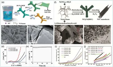
Fig. 4 (a) The illustration of the synthesis of 2D Ni-MOF nanosheet arrays on NF 49; (b) SEM and (c) TEM images of 2D Ni-MOF-250 49;(d) LSV curves of Ni-MOF, Ni-MOF-250, and Ni-MOF-400 49; (e) stability test of Ni-MOF-250 at 270 mV overpotential 49; (f) illustration of the preparation of NF@Ni/C composites 51; (g) SEM and (h) TEM images of NF@Ni/C 51; (i) LSV curves and (j) Tafel plots of NF@Ni/C samples 51.
Carbonaceous nanomaterials can be fabricated when Ni-MOFs are heat-treated in an inert gas atmosphere. These nanomaterials with Ni wrapped in carbon shell can not only retain the high electrocatalytic activity of nickel, but also prevent its corrosion in harsh electrolytic environment. The catalytic performance of these composites can be adjusted by adjusting the composition and structure of the carbon layer. Xuet al.42calcined Ni-MOF in a nitrogen atmosphere, converting Ni2-(BDC)2ted (ted = tri-ethylenediamine) nanosheets to Ni nanoparticles (Ni NPs) with the diameters of 20–30 nm encapsulated in few-layer nitrogen-doped graphene (Ni@NC).The N-doped graphene layer derived from MOF can provide good conductivity and stability for electrochemical reaction.However, the best catalytic performance was obtained when the annealing temperature was 800 °C, which was due to the reduction of defects and amorphous carbon content and partial oxidation of Ni in the sample at 900 °C. Similarly, Ni-BDC was directly grown on NFviaa hydrothermal method by Sunet al.51(Fig. 4f). The prepared NF@Ni-BDC annealed in a mixed atmosphere of hydrogen and nitrogen at 400–700 °C for 2 h would produce multi-layered graphene and multi-walled carbon nanotubes in NF@Ni/C (Fig. 4g,h). With the increase of annealing temperature, the degree of graphitization would increase, but when the calcination temperature was too high(over 700 °C), the catalytic activity would be affected by agglomeration of Ni NPs. Therefore, when the calcination temperature was 600 °C, the sample had the best performance(Fig. 4i,j). The NF@Ni/C-600 achieved small overpotentials of 265 and 353 mV at anode current densities of 10 and 50 mA·cm−2, respectively.

Fig. 5 (a) The illustration of the synthesis of CNH-D-NiMOF 52;(b) DSC-TG curves of CNH-D-NiMOF 52; (c) LSV curves of CNH-D-NiMOF 52.
In order to improve the electrical conductivity and stability of MOF materials, it is a good way to introduce other conductive materials and design the structure. By introducing carbon nanohorns (CNHS), a carbon material with high stability in high temperature and polar solvents, a core-shell structure catalyst was designed by Guoet al.52As shown in Fig. 5a, structure of core-shell CNH-D-MOF was formed by introducing dopamine coating layers on the CNH surface and then nucleating MOFs on surface of dopamine layers.In situnucleation of Ni-MOF was anchored on the surface of CNH PDA due to the interaction between Ni and N atoms.In situnucleation of Ni-MOF was based on the fact that Ni was anchored on the surface of CNH PDA due to the interaction between Ni and N atoms. Compared with Ni-MOF (440 mV), CNH-D-NiMOF showed much lower overpotential of 320 mV at 10 mA·cm−2. They also used PDA and Ni-MOF as carbon and nitrogen sources to pyrolyze in argon atmosphere to obtain Ni-based nanoparticle-embedded N-doped CNH. Through the analysis of the composition of samples pyrolyzed at different temperatures (Fig. 5b), it was found that the organic ligands of MOF decomposed and formed derivatives between 250 and 400 °C. From 400 to 600 °C, the structure of Ni-MOF collapsed seriously, and Ni2+gradually transformed into Ni metal, which greatly reduced the content of Ni―N.Finally, CNH-D-NiMOF-400 achieved the best OER performance with an overpotential of 120 mV at 10 mA·cm−2.When the current density reached 100 mA·cm−2, the overpotential of CNH-D-NiMOF-400 was only 340 mV, which is superior to the commercial noble-mental catalyst (Fig. 5c).
In order to obtain excellent catalysts by oxidation and carbonization of Ni-MOFs, it is important that the structure of Ni-MOFs can be kept stable and the metal/metal oxides can still be uniformly dispersed in the framework of MOF. Therefore, it is necessary to accurately control the temperature of different systems to obtain the best calcination temperature.
4.1.3 Pure Ni-MOF derived phosphates and sulfides
For metal-based compounds, P and S atoms on the surface act as proton-acceptor to facilitate the discharge step. The metal formed during carbonization of Ni-MOFs can be further transformed into metal phosphates and metal sulfides.Phosphating of Ni-MOF can not only obtain nickel phosphide with excellent properties, but also have a positive effect on the structure of amorphous carbon. The samples of Ni(OH)2, NiO,and Ni―P were prepared by Yuet al.53through different treatments of a kind of Ni-PBA nanoplates precursor(Ni(H2O)2[Ni(CN)4]), which were applied to OER catalysis to study their activity differences. As shown in Fig. 6a, NiO porous nanoplates were prepared by calcination in air, Ni(OH)2was obtained by ion exchange reaction in alkaline solution, and Ni―P was prepared by low temperature phosphating in argon.The porous Ni―P nanoplates were in the range of 300–400 nm in lateral size. The nickel phosphides in Ni―P were covered by an amorphous carbon layer. Among these samples, Ni―P porous nanoplates achieved the best OER performance. This is mainly due to the fact that the amorphous carbon derived from MOF improves the electrical conductivity of the carbon coated porous nickel phosphide nanoplates. After phosphating, uniform morphology and porous structure are formed, and the active sites exposed by electrochemical reaction are increased. Furthermore,Yanet al.44introduced a new conductive carbon network to Ni-MOF derived phosphate. The nickel metal organic framework(Ni-MOF-74) was implanted into graphene oxide to form ultrafine Ni2P nanocrystals immobilized on reduced graphene oxide (Ni2P/rGO) by low-temperature phosphorylation. By this method, the average size of ultrafine nickel phosphide at about 2.6 nm can be uniformly distributed in the homogeneous carbon(Fig. 6b). Ni2P/rGO on NF showed relatively low overpotential of 250 mV for OER at 10 mA·cm−2with small Tafel slope of 58 mV·dec−1(Fig. 6c,d). Furthermore, Ni2P/rGO also showed a superior long-term durability with no significant decrease after 20 h testing.

Fig. 6 (a) The illustration of the synthesis of Ni(OH)2, NiO, and Ni-P 53; (b) TEM image of Ni2P/rGO 44; (c) LSV curves and(d) Tafel plots of Ni2P/rGO and other samples 44.
Metal sulfides, like metal phosphates, are considered to be excellent catalysts for reducing the overpotential of OER reaction. The most common sulfurization method is to introduce external sulfur source through solvothermal method or calcination method. Jayaramuluset al.54synthesized nitrogendoped graphene oxide/nickel sulfide nanosheets (NGO/Ni7S6)from Ni-MOF-74 on NGOviausing thiourea as sulfur source under solvothermal condition. This method has great influence on the morphology. NGO/MOF composed of nanorods with 10–20 nm in diameter and 200 nm in length was transformed to 2D NGO/Ni7S6nanosheets. Similarly, Heet al.43used TAA(thioacetamide) as sulfur source to partially sulfurize Ni-BDC to prepare layered structure Ni-BDC@NiS. Ni-BDC nanosheets were vulcanized from the outer layer, and the inner part was still Ni-BDC. The degree of partial vulcanization can be controlled by controlling temperature and time. The mass fraction of S increased from 5.6% to 6.7% to 10.2% with the increase of vulcanizing time from 6 h to 9 h to 12 h at 90 °C. At this temperature, the NiS on the surface of the vulcanized sample is amorphous. With the increase of the content of NiS, the interfacial interaction between NiS and MOF is promoted, which can effectively improve the conductivity, charge transfer rate and surface wettability, thus promoting water adsorption. As a result,the samples with higher NiS content in Ni-BDC@NiS had lower overpotential and lower Tafel slope.
Moreover, the element S contained in the MOF ligand can be used to self-sulfidation without adding other sulfur sources. For example, Yanget al.55calcined Ni-vanillic thiosemicarbazone(NiL2, L = C9H10N3O2S) in NH3atmosphere for 2 h to synthesize the hybrid of NiS nanoparticles spread on nitrogen and sulfur codoped carbon substrate (NiS@N/S-C). Another Ni-MOF including S element was preparedviahydrothermal reaction of NiSO4·6H2O and 4,4-bipyridine by Linet al.34In the presence of counter anion SO42−, N-doped Ni-Ni3S2@carbon nanoplates were formed by self-sulfurization after calcination in argon.Interestingly, when additional sulfur source was added for calcination, the sample is completely converted to Ni3S2@carbon composites, which obtained higher overpotential(314.7 mV at 10 mA·cm−2) than Ni-Ni3S2@carbon nanoplates(284.7 mV). It can be seen that the existence of metal Ni is very important to enhance the electrocatalytic activity of OER. It not only accelerated the charge transfer, but also acted as the active component of capacitance in Ni-Ni3S2@carbon composites.
4.2 Ni-based bimetallic MOFs and their derivatives
Compared with single metal MOFs, bimetallic MOFs show unique properties. (1) Bimetallic MOFs contain two kinds of metal active sites, which are conducive to improving the stability of the framework structure, catalytic activity and respiratory effect56; (2) Coordination unsaturation introduced by exchange metal ions can be achieved to improve the gas adsorption and catalytic performance of MOFs; (3) The performance of bimetallic MOFs can be designed and controlled according to the proportion of metal, so as to obtain the MOFs with the required performance57.

Fig. 7 (a) One-step method of MIL-100(FeNi)/NF 64; (b) standard reaction free energy diagram of OER process on MIL-100(FeNi) surface 64;(c) the illustration of the synthesis of NiFe-NFF 66; (d) LSV curves and (e) overpotentials of NixFey-MOF-74 and other samples 57.
As mentioned above, the synthesis methods of polymetallic MOFs are divided into one-pot reaction and post-synthetic exchange (Fig. 7a)58. Polymetallic MOFs can be prepared by using a variety of metal salts as reactantsviaone-pot method(Fig. 7b)59. In this method, the introduced metal cations should react simultaneously to avoid the formation of a mixture of single cation frameworks. In most cases, bimetallic MOFs can be produced when two metal cations are mixed in a secondary building unit. This is true for the preparation of three metal and even ten metal MOFs. In most cases, this synthesis strategy results in the uniform dispersion of the introduced cations. In the polymetallic MOF containing 10 different metals prepared by Yaghiet al.60, Mg, Mn, Fe, Co, Ni, Zn and Cd accounted for more than Ca, Sr and Ba, because Ca, Sr and Ba tend to have higher coordination number. In fact, most of the researches on Ni-MOFs focus on the combination of Ni and Mn, Fe, Co and Zn. Furthermore, some polymetallic MOFs which are difficult or cannot be obtained by one-pot method can be realized by postsynthetic exchange. As shown in Fig. 7c, a single metal MOF is immersed in a metal ion solution for (incomplete) metal exchange at a certain temperature and time61. The absorption process of cation exchange requires a large amount of excess metal cations to drive.
4.2.1 NiFe-MOFs
4.2.1.1 NiFe-MOFs and their compounds
In recent years, a large number of studies have shown that doping iron into nickel-based materials can effectively improve OER catalytic performance62,63. Liet al.64synthesized MIL-100(FeNi) directly on NF by one-pot method (Fig. 8a). The MIL-100(FeNi)/NF possessed a low overpotential 243 mV to reach a high current density of 100 mA·cm-2and a low Tafel slope value of 30.4 mV·dec−1, which is much lower than Fe-MIL-100/NF(53.3 mV·dec−1) and Ni-MIL-100/NF (48.7 mV·dec−1). They simulated the standard reaction free energy of NiFe-MIL-100 by replacing a Ni atom with an Fe atom in MIL-100(Fe) (Fig. 8b).It can be seen that the electronegativity of Fe is less than that of Ni in the second step of speed determination step, and Fe is more easily oxidized. Therefore, NiFe-MIL-100 has lower energy barrier and better catalytic activity due to the synergistic effect of Ni and Fe.

Fig. 8 (a) Two synthesis routes to mixed-metal MOFs 58; (b) The illustration of the synthesis of Fe/Ni-BTC 59; (c) Illustration of the synthesis of CoNi-Cu(BDC) 61.
NF is a common catalyst carrier for providing good conductivity, high mechanical strength and good synergistic effect. Many other kinds of FeNi-MOFs had been synthesized directly on NF to avoid the catalytic effect of binder. Another Fe2Ni MOF/NF was prepared by one-pot method exhibited good chronopotentiometric durability with only 3.7% loss after 50 h at 10 mA·cm−2by Linget al.65. Moreover, Caoet al.66used NiFe foam (NFF) as both metal sources and substrate (Fig. 8c).NiFe-MOF on NFF (NiFe-NFF) were synthesized by the reaction between acidified NFF and ligands. They also added nickel salts and iron salts during the reaction to make NiFe/NFF.NiFe-NFF exhibited a lower overpotentials of 227 mV than NiFe/NFF (232 mV).
Bimetallic Ni-MOF with different metal ratios can be obtained by changing the feed ratio of raw materials, so as to better study the synergistic effect between metals. Zhenget al.57prepared NixFey-MOF-74 with different Fe/Ni ratios by solvothermal method and named as FeNi-DOBDC-1 (9 : 1), FeNi-DOBDC-2(5 : 1), FeNi-DOBDC-3 (3 : 1) and FeNi-DOBDC-4 (1 : 1). All the samples had similar Fourier Transform infrared spectroscopy(FT-IR) spectra, indicating that they have similar coordination between the metal center and the ligand. In terms of morphology,Ni MOF was polyhedron shape, Fe MOF was regular particles and FeNi-DOBDC was nanosheets. When the content of Fe increased in FeNi-DOBDC, the thickness of nanosheets would increase. FeNi-DOBDC-3 (Fe/sample = 17% (w)) with regular nanosheet morphology showed 287 mV at 100 mA·cm−2which was better than that of commercial RuO2(454 mV at 100 mA·cm−2), and its Tafel slope was only 49 mV·dec−1(Fig. 8d,e).In the Brunauer-Emmett-Teller (BET) test, FeNi-DOBDC-3 showed the largest surface area (77.9 m2·g−1) and largest pore volume among all the FeNi-DOBDC samples. In the case of the same structure, better morphology with larger specific surface area and porous structure is particularly important.
In order to design the morphology more accurately, some researches choose to convert the precursor with large specific surface area into MOF and keep the original morphology. Yanget al.67chose NiFe-layered double hydroxide nanoarray as sacrificial template to synthesize a highly oriented layered NiFe-MOF nanoarray grown on NF (NiFe-MOF/NF). By CV scanning calculation, Fe0.1-Ni-MOF/NF obtained the largest electric double layer capacitanceCdlof 1.170 mF·cm−2, indicating that it has larger specific surface area and more exposure of active site.Therefore, Fe0.1-Ni-MOF/NF obtained the best catalytic performance. Moreover, iron carbonate hydroxide (FeCH)nanoplates on NF was chosen by Duet al.68as semisacrificial template and precursor to prepare NiFe-MOF/FeCH-NF. The size and thickness of the NiFe-MOF nanoplates were varied by control of the semisacrificial template. The prepared NiFe-MOF/FeCH-NF exhibited excellent stability with no obvious decay for 50 h at 10 mA·cm−2.
Ultrathin nanosheets (NSs) with large specific surface area can provide fast mass transfer and charge transfer69. Therefore,it is an effective way to design ultra-thin nanosheets to improve the OER performance of NiFe-MOF. As shown in Fig. 9a,b, an ultrathin Ni-Fe-MOF NSs with a thickness of 1.67 nm to 2.58 nm was designed by Liet al.70In this experiment, a mixed solvent of water andN,N-dimethylacetamide (DMAC) was used.DMAC can dissolve the ligands well, and deionized water can occupy the metal coordination sites on the surface of polymer layers to restrict the growth of coordination polymers. TheCdlof Ni-Fe-MOF NSs was high to 1.50 mF·cm−2. Ni-Fe-MOF NSs showed a low overpotential of 221 mV at a current density of 10 mA·cm−2(Fig. 9c). Wanet al.21synthesized a flower-like Fe-Ni methylimidazole MOFs (FexNi1−x-MOF). The average thickness of Fe0.38Ni0.62-MOF nanosheets was about 6.1 nm. Flower-like Ni-MOF was synthesized by hydrothermal method with CTAB surfactant, and then the samples were obtained by ion exchange in Fe(NO3)3solution (Fig. 9d,e). The mole ratio of Fe/Ni was controlled by the ion exchange time. Among all the samples,Fe0.38Ni0.62-MOF/CC only required 190 mV overpotential at 10 mA·cm−2.
4.2.1.2 NiFe-MOF derived oxides/hydroxides/carbonaceous materials
NiFe-MOFs can be transformed into porous metal oxide nanostructures through a simple and repeatable heat treatment process. Ferronickel oxide is a typical kind of bimetallic electrocatalysts. The NiFe2O4of spinel structure can provide more active sites than that of NiO and Fe2O3, which is beneficial for OER process23. Jianget al.71converted Fe-Ni-based aminoterephthalate MOFs into Fe-Ni-Oxby calcination in air.The Fe/Ni ratio significantly affected the morphology and phase composition of the obtained Fe-Ni-Oxsystem. When the ratio was 1, Fe0.5Ni0.5Oxcomposed of NiO and NiFe2O4presented the best OER activity. Another NiFe-MOF derived NiFe2O4was obtained by two steps to avoidin situcarbide agglomeration by Fanget al.72NiFe-MOFs was calcined into carbon nickel iron alloy at 800 °C in nitrogen atmosphere, and then converting to NiFe2O4by calcination at 500 °C in air. The resulting NiFe2O4/NF electrode had good catalytic efficiency (293 mV at 10 mA·cm−2) and high stability (20 h at 10 mA·cm−2). In addition, Srinivaset al.73obtained mixed metal alloy (FeNi3)and metal oxide (Fe3O4) nanoparticles homogenously anchored on MOF nanosheets and carbon nanotubes (FeNi3-Fe3O4NPs/MOF-CNT) by controlled calcination of NiFe-MOF/CNT composites in nitrogen. After heat treatment at 400 °C for 1 h,part of NiFe0.5-MOF can be transformed into FeNi3and Fe3O4heterogeneous particles on the basis of maintaining the framework of crystalline NiFe0.5-MOF. With the addition of carbon nanotubes, the overpotential at 10 mA·cm−2of NiFe0.5-MOF/CNT@400 decreased from 261 mV to 234 mV. Its Tafel slope was only 37.0 mV·dec−1.
Most MOFs containing metal, carbon and nitrogen can be easily converted intoin situnitrogen doped carbon coated catalyst by controlled pyrolysis. Nitrogen doping can improve the carbon environment of the active sites and greatly enhance the catalytic activity of the materials. At the same time, the transition metals Fe and Ni can catalyze the formation of CNTs74.Taoet al.33obtained FeNi alloy nanoparticles coated in N-doped MWCNTs (FeNi@N-CNT) after the thermal decomposition of NiFeZn-ZIF (ZIF-8 structure). Because the boiling point of Zn is only 900 °C, Zn can be completely removed by evaporation in Ar atmosphere during thermal decomposition at 1000 °C. As shown in TEM (Fig. 10a,b), FeNi Alloy nanoparticles were embedded in the end of CNT with an average diameter of 40 nm and surrounded by about 10 graphene layers. Fig. 10c is the TEM image of the sample after 10 h OER cycle at 10 mA·cm−2, which was exactly the same as before OER reaction. The alloy nanoparticles were still well wrapped by graphite carbon layer,which showed that the structure has not collapsed and has good stability (Fig. 10d).

Fig. 9 (a) Illustration of the synthesis of ultrathin Ni-Fe-MOF NSs 70; (b) AFM image of ultrathin Ni-Fe-MOF NSs 70; (c) overpotentials of Ni-MOF NSs and ultrathin Ni-Fe-MOF NSs 70; (d) illustration of the synthesis of flower-like FexNi1-x-MOF 21; (e) SEM image of flower-like FexNi1-x-MOF 21.

Fig. 10 (a, b) TEM images of FeNi@N-CNT 33; (c) TEM image of FeNi@N-CNT after OER measurement for 10 h 33;(d) Potentiostatic measurement of FeNi@N-CNT 33; (d) illustration of the synthesis of Fe-Ni@NC-CNTs 75; (e) SEM image of Fe-Ni@NC-CNTs 75; (g, i) TEM images of Fe-Ni@NC-CNTs 75; (j) LSV curves of Fe-Ni@NC-CNTs 75.
In order to synthesize FeNi@N-doped carbon CNTs (Fe-Ni@NC-CNT), nitrogen free MIL-88-Fe/Ni nanorods and dicyandiamide (DCDA) were pyrolyzed at 800 °C for 3 h in an inert atmosphere by Zhaoet al.75. The ammonia produced during the decomposition of DCDA is conducive to the reduction of metal ions to metals, thus promoting the formation of CNTs(Fig. 10e). As in the previous case, as shown in the Fig. 10f–i,there is a graphite layer on the wall of the carbon nanotube,which is not parallel to the axis direction of the nanotube,resulting in defects to promote catalytic activity. Both FeNi3and NiFe2O4nanoparticles were embedded in graphitic carbon layers. Fe-Ni@NC-CNT achieved a low overpotential of 274 mV at 10 mA·cm−2.
4.2.1.3 NiFe-MOF derived phosphates/sulfides
The introduction of heteroatoms into NiFe bimetallic catalysts, such as the formation of phosphates and sulfates, will further adjust the electronic structure and promote the electron transport in the OER process. Using NiFe-PBA as template,(NixFe1−x)2P hollow nanocubes were synthesizedviadirect phosphating process by Zouet al.76. (NixFe1−x)2P with different Ni/Fe ratios can be obtained by using different ratios of nickel salt and Fe(CN)6ligands. The (Ni0.62Fe0.38)2P hollow nanocube electrode delivered an overpotential of 290 mV at 10 mA·cm−2,which is much lower than that of Ni-Fe PBA (430 mV).Furthermore, the introduction of graphene and other carbon materials can further increase the catalytic activity and stability.Fanget al.77reported a sheetlike Fe-Ni-P/reduced graphene oxide composite (Fe-Ni-P/rGO) transformed from a composite of porphyrinic MOF (PCN-600-Ni) and graphene oxide. The overpotential of Fe-Ni-P/rGO-400 to achieve at 10 mA·cm−2was as low as 240 mV, which is lower than its precursor.
In order to explore the effect of different atom doping on the catalytic performance, the NiFe-PBA was treated with phosphating, boronizing and sulfurization, and the synthesized Ni-Fe-O-P, Ni-Fe-O-B, and Ni-Fe-O-S were tested by Xuanet al.78. Atomic doping was achieved by calcining in air with phosphorus, boron and sulfur sources. The results showed that the porous cubic structure of PBA was basically preserved in the three materials. At constant current densities of 10 mA·cm−2,there was no significant change after 10 h for the three materials.The values ofη10of Ni-Fe-O-P, Ni-Fe-O-B, and Ni-Fe-O-S were 129, 113 and 84 mV lower than that of the sample without doping (356 mV), respectively. Ni-Fe-O-P also obtained the lowest Tafel slopes of 50 mV·dec−1. This may be attributed to the introduction of P, B or S, which can effectively adjust the electronic structure and accelerate charge transfer, and may lead to higher average oxidation state of Ni species.
4.2.2 NiCo-MOFs
4.2.2.1 NiCo-MOFs and their compounds
As the first transition metal with high theoretical activity, the combination of Co and Ni can optimize the electronic structure and adsorption energy, which is conducive to the electrochemical oxidation of water. The XAS analysis and DFT simulations of ultra-thin Nico BDC nanosheets (NiCo-UMOFNs) prepared by Zhaoet al.37showed how the interaction between Ni and Co, unsaturated coordination effect and ultrathin structure promote the electrocatalytic activity. As shown in Fig. 11a, the free energy barrier of formation of OH* on the Ni5c site is lower, and Ni site can adsorb OH better. However, the ΔG3value of 1.63 eV in Ni-UMOFNs suggests that occupancy of theeg-orbital is too high, and bimetallic bonding can effectively solve this problem. According to the electronic coupling diagram(Fig. 11b) between Co and Ni, there are unpaired electrons in thedorbital of Co2+, while Ni2+is completely occupied. After coupling, the electron repulsion between O2and Ni2+and theπdonation of Co―O result that the electrons will be transferred from Ni2+to Co2+through the oxygen of ligand. This coupling can change the filling ofegorbitals in the two metals and further reduce the free energy barrier to promote the reaction. Based on the partial density of states (PDOS) calculation of the (200)surface structure exposed by UMOFNs system, the 3Degstate of coordinated unsaturated metal in Nico UMOFNs is more than that of fully coordinated metal in bulk NiCo-MOFs. Therefore,NiCo-UMOFNs with all the advantages possessed 250 mV overpotential at 10 mA·cm−2, while Ni-UMOFNs, Co-UMOFNs, bulk NiCo-MOFs obtained overpotentials of 321,371 and 317 mV, respectively. The article of Zhouet al.79also confirmed this view. The coupling effect between Ni and Co in the bimetallic CTGU-10 catalyst changed the valence state of single metal ions and the ability of materials to accept electrons.In this experiment, the Co/Ni ratios of CTGU-10a2, b2, c2, d2([NH2(CH3)2][M3(μ3-OH)(H2O)3(BHB)], M3= CoxNi3−x) were 3 : 0, 2 : 1, 1 : 2 and 0 : 3. Compared with CTGU-10a-d1 series,MOF changed from bulk to nanosheets due to the increase of ligand and metal salt concentration. CTGU-10c2 was a hierarchical nanobelts composed of nanosheets with a thickness of only 1 nm. CTGU-10c2 achieved the best OER activity with a 240 mV overpotential at 10 mA·cm−2and a Tafel slope of 58 mV·dec−1.
Due to the unique local surface plasma resonance (LSPR) of noble metal nanostructures, the introduction of noble metal atoms into NiCo-MOF catalyst is an effective strategy. Huet al.80decorated Au nanorods (AuNRs) on the 2D layered ultrathin NiCo-MOF with a thickness of 6.6 nm. In the condition of an 808 nm laser (200 mW),the overpotential at 10 mA·cm−2of AuNRs on NiCo-MOF decreased from 283 to 240 mV, and the Tafel slope reduced from 83 to 69 mV·dec−1. Under the appropriate bias voltage, the hot porous AuNRs produced by plasma can be injected into the Ni active sites, which significantly increases the formation of high valence nickel active substances in MOFs, thus reducing the activation energy of OER.
Moreover, Liet al.81grew M2(BDC)2TED nanosheet arrays(M = Co, Ni and Co/Ni) directly on Cu foam (CF) substrates with large pore and specific surface area (M2-(BDC)2TED@CF).Through liquid-phase epitaxial layer-by-layer method, the pretreated CF was immersed in ethanol solution of metal ions and mixed organic ligands (BDC/TED) in turn and cycled for many times (Fig. 11c). In this method, the number of cycles can control the Co/Ni ratio. When the Co/Ni ratio was 1/1 (40 cycles), the current density to reach 10 and 50 mA·cm−2required overpotentials of only 260 and 287 mV, respectively (Fig. 11d).Compared with the rapid decline of single metal composite (Fig.11e), the synergistic effect of Co/Ni in NiCo(BDC)2TED@CF enhanced the electrocatalytic activity and cycle performance.

Fig. 11 (a) Gibbs free energy diagram of UMOFN surface 37; (b) electronic coupling diagram between Co and Ni 37;(c) illustration of the synthesis of M2-(BDC)2TED@CF 81; (d, e) LSV curves and chronoamperometry curves of M2-(BDC)2TED@CF 81.
4.2.2.2 NiCo-MOF derived materials
NiCo-MOF is also used for conversion to oxides and carbonaceous materials. NixCo3−xO4nanoarrays on NF(NixCo3−xO4/NF) was synthesized by calcining NiCo-PBA/NF in air by Shenet al.82According to the schematic diagram in Fig.12a, nickel hydroxide arrays were formedin situin NF, and then immersed in K3[CoIII(CN)6] for 30 h. The surface of the original smooth nanoplates was replaced by dense porous and hollow nanocubes (Fig. 12b). DFT calculation was carried out on most frequently exposed NiO (100) and Ni2CoO4(001) surfaces, and was concluded that the active sites of NiO and Ni2CoO4are Ni bridge site and Co top site, respectively (Fig. 12c,d). In contrast,the theoretical OER overpotential of Ni2CoO4is 0.56 V, which is lower than that of NiO (0.67 V). It means bimetallic Ni2CoO4exhibited better intrinsic OER activities than the single metal oxide NiO. Due to the porous and hollow structure and the existence of Ni2CoO4, the overpotential NixCo3−xO4/NF electrode needed only an of 287 mV achieving the current density of 10 mA·cm−2(Fig. 12e). It showed 24 h long-cycle stability. Moreover, Weiet al.83oxidized NiCo-MOF(Ni3[Co(CN)6]2) microcubes to NiO/Co3O4concave surface microcubes (NCMC). Calcination caused the square of the circle to shrink, and each surface was concave, but its shape still maintained. The NCMC also showed good OER performance with a 290 mV overpotential at 10 mA·cm−2. This is due to the production of Co3O4, which also has an active spinel structure.
Co/Ni-MOF-74 derived carbon-coated core-shell CoxNi1−xand CoyNi1−yO nanoparticles were reported by Sunet al.84The nanoparticles with ~3.2 nm in core diameter and ~2.4 nm in shell thickness were embedded uniformly in the ligand-derived carbon matrix. When the Co: Ni ratio of precursor was 1 : 1, the best performance was obtained. Pinget al.36used NiCoLDH/NF precursor and imidazole-based ligands to form NiCo-MOFin situon NiCoLDH surface. After subsequent carbonization, the obtained NiCo alloy@C/NixCo1−xO/NF hierarchical composite showed the Tafel slope of 106 mV·dec−1. In addition, Jiaet al.85produced Co-doped Ni3C/Ni-embedded carbon materials by carbonization of Co/Ni-BTC in reducing atmosphere. The amorphous carbon formed by calcination can prevent the polymerization of metal particles and act as electron conduction.In addition to the internal derived carbon, Fenget al.86introduced polyacrylonitrile (PAN) as the template of nitrogen doped carbon matrix. By using electrospinning technology, Ni-Co BTC and PAN were mixed evenly, and the columnar morphology with a diameter of 800 nm was formed. After calcining in inert atmosphere, NiCo alloy nanoparticles in 0.35 nm multiple graphitic carbon shells were uniformly embedded in the columnar.
Another class of electrocatalyst is NiCo phosphates and sulfides, which have been explored to perform promising OER activities. Yanet al.87synthesized nickel-cobalt bimetal phosphide nanotubes (CoxNiyP NTs). CoxNiyO was obtained by calcining NiCo-MOF-74 with different ratio of Co/Ni at 350 °C in air atmosphere, and then CoxNiyP (complex solid solution structure) was obtained by phosphating at 300 °C in a N2atmosphere. Co1Ni4P (Co/Ni ratio is 4 : 1) still maintained the tubular structure of NiCo-MOF-74, with large specific surface area and porous structure. The obtained CoxNiyP NTs exhibited a low overpotential of 245 mV to reach 10 mA·cm−2. Like NiFe alloy, Nico alloy can promote the growth of carbon nanotubes in the process of carbonization. Fanet al.88prepared NiCo-BTC derived cobalt nickel bimetal phosphide (Ni,Co)2P nanoparticles(NPs) encapsulated in nitrogen-doped carbon nanotube hollow microspheres (NCNHMs) (Fig. 13a). NiCo-BTC hollow spheres were prepared by using polyvinylpyrrolidone (PVP) as stabilizer. After calcined at 800 °C in nitrogen atmosphere, metal ions in MOF would be converted into metal nanoparticlesin situ,and BTC would be catalyzed to form nitrogen doped nanotubes,which extended from the hollow porous carbon shell (Fig. 13b).After phosphating the metal, Ni1.4Co0.6P/NCNHMs achieved a much lower overpotential than Ni1.4Co0.6/NCNHMs (Fig. 13c).In most studies, oxidation or carbonization followed by phosphating are used to prevent the structure damage caused by phosphating. However, Shuaiet al.38directly phosphated NixCoy-BDC nanosheets precursors, and obtained that Ni2P and Co2P coexisted uniformly in the amorphous carbon framework(NixCoy-P). And theη35of Ni1Co1-P catalyst on NF was low to 300 mV in 1.0 mol·L−1KOH solution.

Fig. 12 (a) Illustration of the synthesis of NixCo3-xO4/NF 82; (b) TEM image of NixCo3−xO4/NF 82; adsorption of the OH* on (c) Ni2CoO4 (001) and(d) NiO (100) 82; (d) LSV curves of NixCo3−xO4/NF and other samples 82.
Ni-Co based sulfonated nanoparticles embedded in N,Scodoped porous carbon was synthesized by carbonization and vulcanization of Ni substituted ZIF-67 at the same time by Chenet al.89Due to the substitution of Ni, high porosity, uniform dispersion of active components and N, S codoping, it showed excellent activity and stability in OER. In addition, Chenet al.90used the CoNi-MOFin situgrown on the substrate CC as the template, and obtained the final product hierarchical porous Ni-Co-S nanosheets arrays on CC (Ni-Co-S HPNA/CC) by oxidation and subsequent vulcanization. In the Fig. 13d, the sulfur atom completely replaces the oxygen atom to form pure Ni-Co-S HPNA. Ni-Co-S HPNA maintained the morphology of CoNi-MOF (Fig. 13e). The sample showed a low overpotential of 270 mV at 10 mA·cm−2and a low Tafel slop of 80 mV·dec−1(Fig. 13f,g). At the same time, it was much lower than that of Co-S HPNA (320 mV at 10 mA·cm−2). The synergism of bimetallic MOFs is demonstrated again.
4.2.3 Other Ni-based bimetallic MOFs and their derivatives
In addition to Fe and Co, Cu, Mo, Zr and other metals can form bimetallic MOF with Ni. Maet al.91reacted 10 nm Cu-Ni particles with 2,5-dihydroxytetraphenylic acid to obtain the structure of Cu-Ni particles encapsulated in CuNi MOF. The Tafel slope of the structure (98 mV·dec−1) is lower than that of Cu-Ni particles (108 mV·dec−1) and Ni-MOF-74 (108 mV dec−1). Zhenget al.92directly grown uniform CuNi-MOF nanosheets on NF. The overpotential of CuNi-MOF/NF catalyst was 309 mV at 100 mA·cm−2. In addition, the catalytic activity remained stable for at least 22 h in 1.0 mol·L−1KOH.Ni/Ni2P/Mo2C nanoparticles encapsulated in porous graphene shells (Ni/Ni2P/Mo2C@C) derived from NiMo-MOFviaa carbonization and phosphating process was reported by Liet al.93.Due to the synergistic effect of evenly distributed particles and highly stable porous carbon coating, the catalyst has durability in both acid and alkali. In the environment of 1 mol·L−1KOH,the catalyst showed overpotential of 368 mV at 10 mA·cm−2.
4.3 Ni-based trimetal MOFs and their derivatives
Iron group elements such as Fe, Co and Ni are the key elements of non-noble metals catalytic in OER. The reason is that they are relatively rich, cheap, environmentally friendly and have unique redox characteristics. As mentioned above, Fe or Co doping can synergistically enhance the electrocatalytic activity of Ni-MOFs and their derivatives. The performance of Trimetal catalysts can be further improved on the basis of the excellent performance of bimetallic catalysts. This synergistic enhancement of electrocatalytic activity is not only reflected in Ni-based MOF, but also widely reported in its derived mixed systems of oxides, hydroxides and hydroxides.

Fig. 13 (a) Illustration of the synthesis of Ni1.4Co0.6P/NCNHMs 88; (b) SEM image of Ni1.4Co0.6P/NCNHMs 88; (c) LSV curves of Ni1.4Co0.6P/NCNHMs and other samples 88; (d) illustration of the synthesis of Ni-Co-S HPNA/CC 90; (e) SEM image of Ni-Co-S HPNA/CC 90;(f) LSV curves and (g) Tafel slope of Ni-Co-S HPNA/CC 90.
A rod shaped Fe/Ni/Co MOFs (BDC ligand with MIL-53(Fe)structure) were synthesizedviasolvothermal reaction by Liet al.94Interestingly, they first synthesized Fe/Ni Bimetallic MOFs by controlling the ratio of Fe/Ni. The results showed that the sample with a ratio of 1 : 4 had a low overpotential of 244 mV and a Tafel slope of 37.8 mV·dec−1, which was much lower than that of Ir/C (310 mV and 53.8 mV·dec−1). Then, with this ratio of Fe/Ni, by adjusting the amount of cobalt ions introduced, all the trimetal metal MOFs obtained better OER performance than Fe/Ni2.4-MIL-53. The overpotential of Fe/Ni2.4/Co0.4-MIL-53 was as low as 219 mV. At a potential of 1.50 V (vs.RHE), it can deliver 79.6 mA·cm−2, which was two times higher than that of Fe/Ni2.4-MIL-53 (33.6 mA·cm−2). In addition, Yuanet al.95synthesized Co2.36Fe0.19Ni0.45-btca by introducing Fe2+and Ni2+into Co-MOF (Co3(OH)2(BTCA)2, H2btca = benzotriazole-5-carboxylic acid). In the MOF structure with the same onedimensional channel and unsaturated coordination metal center,the overpotential of the trimetal catalyst was 292 mV at 10 mA·cm−2, which was lower than that of single metal and bimetallic catalyst. It also maintained 90% current density even after 74 h of continuous tests.
A novel NiCo/Fe3O4/MOF-74 hybrid material was prepared by Wanget al.96through controllable pyrolysis of trimetal NiCoFe-MOF-74. As shown in the Fig. 14a, the NiCoFe-MOF-74 was partially decomposed at 400 °C. Due to the strong binding strength between Fe and O ligands (Fig. 14b), MOF-74 particles of NiCo alloy core and Fe3O4thin shell formed by pyrolysis are uniformly anchored on the high-specific-area MOF-74 skeleton (Fig. 14c). The hybrid structure has better performance than MOF-74 completely decomposed at high temperature, with 238 mV overpotential at 10 mA·cm−2and 29 mV·dec−1(Fig. 14d,e). The DFT calculation of NiCo/Fe3O4surface also showed that encapsulated NiCo/Fe3O4heteroarticles in the substratum exposed much enhanced activity than those with NiCo nanoalloy and those with Fe3O4nanocrystal.

Fig. 14 (a) Illustration of synthesis of NiCo/Fe3O4/MOF-74 96; (b) free energy diagram of the elementary electrochemical steps on NiCo/Fe3O4 96;(c) HAADF-STEM image of NiCo/Fe3O4 96; (d) LSV curves and (e) Tafel slope of NiCo/Fe3O4/MOF-74 calcined at different temperature 96;(f) illustration of synthesis of FeCoNi-LDH 97; (h) chronopotentiometry curve of FeCo0.5Ni0.5-LDH 97.
FeCoNi MOF was also used as a precursor to prepare FeCoNi-LDH with excellent catalytic activity and stability97. As shown in the Fig. 14f, afterin situgrowth of trimetallic oxalate MOF on Cu foil, the hydroxide occupies the oxalic acid position to coordinate with metal ions in alkaline solution. Then, trimetallic MOF transformed into LDH nanosheets (about 1 nm thick).Because the MOF is octahedrally coordinated by Fe, Co and Ni atoms with six O atoms of the three bidentate oxalate ions, its crystal structure is similar to that of LDH, and the microstructure is also layered, which are conducive to the conversion process.Finally, FeCo0.5Ni0.5-LDH showed highly efficient OER performance with a low overpotential of 248 mV at a current density of 10 mA·cm−2and long-term stability (little change after 50 h), thanks to the large area of the layered ultrathin sheet providing exposed active sites, fast conductivity and multi metal collaborative optimization of electronic structure (Fig. 14g).Next, two kinds of different sulfurization treatments are introduced to achieve the purpose of introducing nickel sulfide into the final product. Ahnet al.98synthesized NiCo-PBA,NiCoFe-PBA and NiFe-PBA by precipitation method. These nanocubes and sodium sulfide (Na2S) were reacted in the form of ion exchange (S2−) exchange to obtain NC-MOF, NF-MOF,and NCF-MOF, respectively. Because [Co(CN)6]3−and[Fe(CN)6]3−have different ion exchange rates, the morphology and composition of the three products are affected in varying degrees. The rapid exchange of [Co(CN)6]3−with sulfur ions resulted in high porosity. The relatively inactive of [Fe(CN)6]3−induced the decomposition of CN group and produced active pyridine nitrogen doping. Therefore, the amorphous NiS doped NCF-MOF is a multi-stage porous 180 nm nanocube with connected pores and small holes on the inner and outer surfaces,respectively. When NF was used as the substrate, NCF-MOF was 0.48 V overpotential at 30 mA·cm−2with the small slope of 49 mV·dec−1. Yuanet al.99synthesized core-shell Ni3S2@NiFeCo-MIL-53 nanowires grow on NF (Ni3S2@MIL-53(NiFeCo)/NF) by reacting Ni-Co PBA/NF nanocubes with terephthalic acid ligand, ferrous salt and Na2S together. In this solvothermal reaction, Ni-Co PBA forms the crystal nucleus of metal sulfide through ion exchange, and the Ni and Co ions provided by PBA combine with the external introduced Fe ions to form MIL-53 on the surface of metal sulfide. This material had excellent OER electrocatalytic properties with 236 and 249 mV overpotentials at high current densities of 50 and 100 mA·cm−2, respectively. At 1.53 V in O2-saturated 1.0 mol·L−1KOH solution for 50 h, there was a slight attenuation.
5 Conclusion and prospect
As a new type of multifunctional material, the preparation,characterization and properties of Ni-MOFs have been developed rapidly in recent years. In this paper, the research progress of Ni-MOFs and their derivatives as OER electrocatalysts was reviewed from the aspects of related mechanism, synthesis strategy and electrocatalytic performance.Their electrochemical properties are compared in details in Tables 2 and 310,22,26,31,33,36–38,41–44,46–49,56,57,59,61,64–68,70–73,75–90,92–112. For the development of Ni-MOFs based electrocatalysts with high activity and high stability, the strategy mainly includes the following aspects: (1) The Ni-MOFs were controllable oxidized,carbonized, phosphated or sulfurized to guide the metal/metal oxide/metal phosphide/metal sulfide to disperse uniformly in the MOF framework. At the same time, incomplete transformation can make better use of the structural advantages of MOF. (2)Other metal nodes can be introduced into MOFs to improve the catalytic efficiency. Among them, iron and cobalt, which are both iron series elements, show synergistic effect better than other metals. This also applies to MOF and its derived metaloxides, metal hydroxides, metal phosphides, metal sulfides and carbonaceous compounds. (3) By selecting suitable nitrogencontaining ligands, nitrogen-containing carbon derivatives can be easily obtained. Nitrogen doping can often change the charge density (spin density and charge distribution) of C atoms around N atoms, so as to regulate the surface chemical activity of materials, generate active sites, and effectively improve the electrocatalytic performance of materials. (4) MOF is directly grown on the collector, which avoids the use of polymer binder,significantly improves the conductivity, activity and stability of the electrocatalyst. (5) Ni-MOFs were compounded with conductive materials (such as graphene, carbon nanotubes,etc.)to improve catalytic activity and stability; (6) The morphology of Ni-MOFs was designed, such as ultra-thin nanosheets with large specific surface area or complex core-shell structure, to better expose the active sites and improve the mass transfer and catalytic activity;
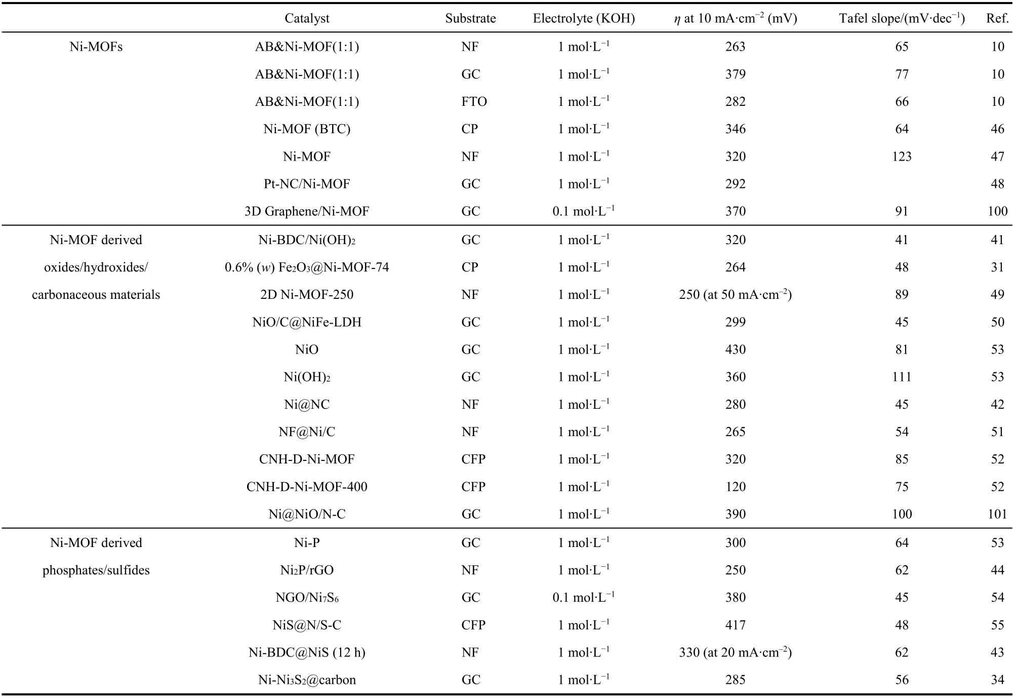
Table 2 Comparison of the OER performance of pure Ni-MOF and their derivatives materials.

Table 3 Comparison of the OER performance of bimetallic and trimetallic Ni-MOFs and their derivatives materials.

continued Table 3
Although some progress has been made in electrocatalysts based on Ni-MOFs and their derivatives, there are still some challenges. Firstly, through theoretical calculation, some papers have explored the active sites and mechanisms of some Ni-MOFs and polymetallic Ni-MOFs. However, there are still different opinions on the determination of the rate-determining step and the optimal active site. Especially in view of the complexity of MOF structure, it is difficult to determine the actual catalytic active site, which needs more theoretical calculation and experimental exploration. At the same time,combined with theoretical calculation, it is necessary to explore the metal ratio and content with the highest activity and its principle in order to guide the experiment. Second, the combination of somein situcharacterization techniques to observe the reaction process and determine the active sites will help to understand the reaction mechanism and improve the design of catalysts. Third, the design of multifunctional catalysts will be an important direction in the future. Based on the structural characteristics and physical and chemical properties of Ni-MOF materials, they have certain performance in different catalytic processes, such as HER, OER and ORR reactions. The establishment of Ni-MOF multifunctional catalytic materials can not only catalyze different reaction processes at the same time,but also further save the preparation cost of the catalyst. In addition, the synthesis and application of Ni-MOFs and their derivatives as OER electrocatalysts are still limited to the laboratory stage. The large-scale development and application of this material in industry is also a great challenge.
