Dynamic measurement of beam divergence angle of different fields of view of scanning lidar∗
2021-03-11QingYanLi李青岩ShiYuYan闫诗雨BinZhang张斌andChunHuiWang王春晖
Qing-Yan Li(李青岩), Shi-Yu Yan(闫诗雨), Bin Zhang(张斌), and Chun-Hui Wang(王春晖)
National Key Laboratory of Tunable Laser Technology,Harbin Institute of Technology,Harbin 150001,China
Keywords: laser divergence angle,lidar,CCD,different fields of view(FOV)
1. Introduction
Laser technology has been widely used in various fields,such as laser communication, lidar, laser ranging, and space optical communication.[1–5]The system’s requirements for laser beams are also becoming stricter, requiring the laser beam spot energy to be concentrated and the divergence angle in far-field to be small. The laser beam divergence angle is an important parameter of laser quality. On the one hand,it can reflect the divergence characteristics of long-distance transmission. In addition, it can accurately assess the quality of relevant laser instruments and laser transmission quality.[6]Therefore,it is of great significance to accurately measure the minute divergence angle of the laser.
In recent years,due to the promotion of intelligent robots and autonomous driving,lidar has begun to enter into the people’s field of vision,and is widely used in civilian fields,such as sweeping robots,atmospheric and ocean exploration,intelligent transportation, and smart homes.[7–10]The MEMS micromirror has the characteristics of small size, light weight,fast scanning speed, low power consumption, relatively low price, and insensitivity to environmental influence. It has become the first choice device in a miniaturized,high frame rate,high precision three-dimensional image sensor system.[11]The application of MEMS micromirrors to the lidar system solves the miniaturization and solidification of the system. However,due to the small size of the micromirror,its mechanical scanning angle is limited,which effects its large-scale applications.In addition, the outgoing laser beam is generally a Gaussian beam, which has a beam divergence angle, and long-distance scanning will cause a large beam dispersion. For these reasons, in practical applications, the matching optical system will be designed. On the one hand,the outgoing laser beam is collimated to compress the divergence angle; in addition, the scanning field of view is expanded. However,due to the inherent properties of the lens,it is impossible to perfect the imaging,the effects of collimating and expanding the beam will be different at different angles. Therefore,there is an urgent need for a measurement system that can dynamically measure the divergence angles of laser beams in different fields of view for scanning laser systems,thereby evaluating and improving the overall system performance.
For individual lasers,there are several traditional methods of measuring laser divergence angle, such as the focal spot method, the moving knife-edge method, the polarized light interference method, etc. But the above traditional methods have high requirements for the quality of the laser beam. The operation is more complicated and measurement accuracy is low, and the human error is large. These shortcomings reduce the practicability to a certain extent. In addition, the above methods are all aimed at measuring the laser beam at a fixed position and angle.[12]However,the laser is generally not used alone for some specific applications, but combined with other optical systems, such as scanning lidar. In order to realize the dynamic measurement of the divergence angle of the laser beam in the different fields of view of the scanning laser system, we add a circular guide rail and corresponding servo mechanism to the system. Therefore,in this paper we propose a measurement system based on CCD secondary imaging to dynamically measure the divergence angles of MEMS scanning laser radar beams in different fields of view, to achieve the evaluation of the overall system beam quality and optical system performance. The system structure is simple and the measurement accuracy is high.
2. Principle of measurement
In practical applications,the propagation path of the laser beam is not an ideal straight line, and the amplitude of the same wavefront is also unequal. The outgoing beam of most lasers is Gaussian beam, the light field maintains a Gaussian distribution.[13,14]The beam cross-sectional area(w)changes non-linearly with propagation distance(z)as shown in Fig.1.

Fig.1. Nonlinear propagation of the laser beam.
There is a position with the smallest interface in the laser beam, which is called the waist of the laser beam. The radius of the beam waist is represented by w0. The radius of the cross-sectional area of the beam away from the beam waist z can be expressed as
where λ is the wavelength of the laser beam. The cross section of the beam is the smallest at the waist of the beam. The farther the observation point is away from the beam,the larger the beam diameter is, so the laser beam is divergent. Generally,the degree of divergence of the laser beam is represented by the far-field divergence angle 2θ.The divergence angle can be expressed as

When z approaches to infinity,the far-field divergence angle(2θ)of the Gaussian beam can be expressed as

The transmission of the beam in the far field causes the width of the laser beam to increase. Therefore, in this system the CCD secondary imaging method is used to measure the laser divergence angles of different fields of view of the MEMS scanning lidar. The measurement principle is shown in Fig.2. By imaging the laser spot at positions l1and l1,the diameters w1and w2can be measured.

Fig.2. Principle of measuring beam divergence angle by CCD imaging method.
From the analysis in Fig.2, the laser beam divergence angle can be obtained from
From Eq. (4), it follows that the laser beam divergence angle can be accurately calculated by obtaining the spot radii at two positions. The image collected by the CCD is a matrix collection of discrete points. On any cross-section along the axis, the spot center position (x, y) can be expressed by the first moment of the beam intensity as follows:

The laser spot diameters w1and w2can be expressed by the second moment of the light field intensity as follows:

Through the MEMS micromirror control circuit,the laser radar performs point-to-point scanning, and the beam quality analyzer is installed on two sections of circular rails (the rail radii are 0.5 m and 1 m, respectively), and the slider on the rail is driven by a servo mechanism. The beam quality analysis moves to measure the spot diameters in different fields of view.Therefore,the beam divergence angles of different scanning angles can be calculated, and then the collimated beam expansion capability of the optical system and the beam quality of the lidar system can be objectively evaluated.
3. System composition and working process
The measurement system is shown in Fig.3.
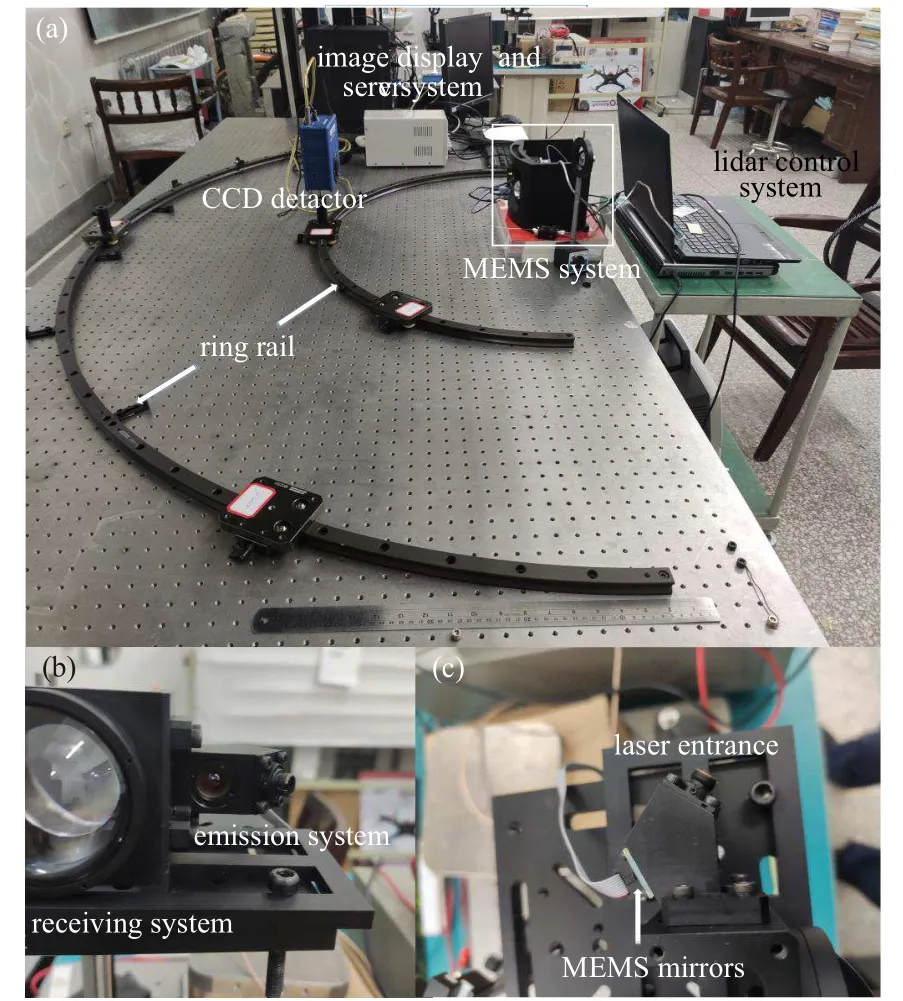
Fig.3. Measurement system.

Fig.4. Schematic diagram of CCD secondary imaging measurement.
The device consists of 1550-nm infrared laser, MEMS scanning micromirror,optical collimated beam expansion system, attenuator, beam quality analyzer, data acquisition card,computer, and two sections of circular guide rails and servo mechanism.
The laser beam emitted by the laser is reflected by the MEMS micromirror and enters into the optical collimating system. The collimated light enters into the CCD camera through the attenuator and the data are sent to the computer for calculation by the data acquisition (DAQ) card. Then, the lidar control system controls the MEMS micromirror to perform point-to-point scanning. The servo mechanism control system drives the slider to slide on the 0.5-m rail with the beam quality analyzer to capture laser beams in different fields of view.Therefore,the spot diameters of different fields of view can be obtained. The same method is used to measure the spot diameter of each field of view at 1 m away. After multiple measurements,the average value is calculated and imported into a computer to calculate the beam divergence angles of different scanning fields of view,and the results are shown in Fig.4.
4. Experiment and data processing
In this design,used are an infrared fiber laser with a wavelength of 1550 nm and an MEMS scanning mirror with a mechanical rotation angle of ±5◦. The angle of the optical system is magnified twice,so the scanning field of view can reach±20◦. Ophir-Spiricon Inc’s beam quality analyzer PY-III-C-A is used to detect the laser beam in the central field of view as shown in Fig.5, and the results show that the laser beam quality is good.
By controlling MEMS micromirror scanning, the laser beam divergence angles at different scanning fields of 0.5 m and 1 m are measured. After repeating the test ten times, the laser divergence angle of each field of view is finally obtained,and the results are shown in Table 1.
According to results in Table 1,the divergence angles of the laser beams in different fields of view of the scanning lidar can be obtained, and the results are shown in Fig.6. It can be seen that the divergence angle of the central field of view is 0.99 mrad. The divergence angle increases slightly as the scanning field of view increases, and the maximum angle is 1.2 mrad. Overall,this is a small difference between the edge and the center field of view, and it can be concluded that the optical collimation system has good performance. In addition,the diameters of the edge field of view in the x direction and y direction are slightly different.It can be seen that the light spot is slightly deformed in the edge field of view. The laser beam energy of the system is concentrated and evenly distributed,the divergence angle is small, and the difference between the edge field of view and the center field of view is small,so the overall performance of the system is good.

Fig.5. (a)Two-and(b)three-dimensional light spots.

Table 1. Beam diameters in different fields of view.

Fig.6. Beam divergence angles of different fields of view.
5. Conclusions
The laser beam divergence angle is one of the important parameters to evaluate the quality of the laser beam. For individual lasers,there are many detection methods,and the detection technology becomes gradually matured. The laser is generally not used alone for some specific applications, but combined with other optical systems, such as scanning lidar.Laser beams in different fields of view need to be measured dynamically. Therefore,in this paper proposed is a system for measuring the divergence angles of beams in different fields of view of the MEMS scanning lidar. The CCD secondary imaging method is used to realize the digital detection and exclude the human error. The test accuracy and detection efficiency are improved,the servo mechanism and the guide rail are controlled to realize the dynamic measurement of different fields of view, and finally the performance of the overall system of the scanning lidar can be objectively evaluated.
Especially for the long-distance scanning lidar, the requirements for the laser beam are very high. The quality of the laser beam in different field of view depends on the optimized performance of the transmitting optical system. The method proposed in this paper can effectively detect the quality of the laser beam in different fields of view of the scanning lidar,and evaluate the performance of the transmitting optical system and the overall system.Then the timely adjustment can be made to maximize the overall performance.
猜你喜欢
杂志排行

Chinese Physics B的其它文章
- Novel traveling wave solutions and stability analysis of perturbed Kaup–Newell Schr¨odinger dynamical model and its applications∗
- A local refinement purely meshless scheme for time fractional nonlinear Schr¨odinger equation in irregular geometry region∗
- Coherent-driving-assisted quantum speedup in Markovian channels∗
- Quantifying entanglement in terms of an operational way∗
- Tunable ponderomotive squeezing in an optomechanical system with two coupled resonators∗
- State transfer on two-fold Cayley trees via quantum walks∗