Modification of exposure conditions by the magnetic field configuration in helicon antenna-excited helium plasma
2021-03-01TianyuanHUANG黄天源PeiyuJI季佩宇JianjunHUANG黄建军BinYU于斌andXuemeiWU吴雪梅
Tianyuan HUANG(黄天源),Peiyu JI(季佩宇),Jianjun HUANG(黄建军),Bin YU (于斌) and Xuemei WU (吴雪梅)
1 College of Physics and Optoelectronic Engineering, Shenzhen University, Shenzhen 518060, People’s Republic of China
2 Key Laboratory of Optoelectronic Devices and Systems of Ministry of Education and Guangdong Province, College of Physics and Optoelectronic Engineering, Shenzhen University, Shenzhen 518060,People’s Republic of China
3 Advanced Energy Research Center,Shenzhen University,Shenzhen 518060,People’s Republic of China
4 School of Physical Science and Technology,Soochow University,Suzhou 215123,People’s Republic of China
Abstract Modification of exposure conditions downstream in the diffusion chamber has been performed in helicon antenna-excited helium plasma by adjusting the magnetic field(intensity and geometry).In the inductively coupled mode (H mode), a reduction in ion and heat fluxes is found with increasing magnetic field intensity, which is further explained by the more highly magnetized ions off-axis around the last magnetic field lines (LMFL).However, in helicon wave mode (W mode),the increase in magnetic field intensity can dramatically increase the ion and heat fluxes.Moreover, the effect of LMFL geometry on exposure conditions is investigated.In H mode with contracting LMFL,off-axis peaks of both plasma density and electron temperature profiles shift radially inwards,bringing about a beam with better radial uniformity and higher ion and heat fluxes.In W mode,although higher ion and heat fluxes can be achieved with suppressed plasma cross-field diffusion under converging LMFL, the poor radial uniformity and a small beam diameter will limit the size of samples suitable for plasma irradiation experiments.
Keywords: helicon wave plasma, plasma source, magnetized plasma, plasma diagnostics
1.Introduction
Helicon wave plasma (HWP) sources, which are capable of producing steady-state high-density plasmas(1018to 1019m−3)with a low electron temperature(<10 eV)over a wide range of power levels, neutral pressures, magnetic field strengths and geometries,have been considered as prominent ion sources for fusion-related materials testing platforms [1-4].Fusion-related materials testing is always performed by processing wall material samples with plasmas under pre-selected exposure conditions such as ion energy, flux and fluence [5, 6].As two crucial parameters for exposure condition tuning in HWP sources, an increase in magnetic field or radiofrequency (RF)power can trigger mode transitions from capacitive mode(E mode) to inductive mode (H mode) and then to helicon wave mode (W mode) [7, 8].Due to the different plasma generation mechanisms [9], mode transitions are always accompanied by abrupt changes in plasma density and distribution which are crucial for the modification of exposure conditions in HWP devices.
For devices with a uniform static magnetic field geometry, HWP plasma beams usually present a center peaked density profile across the radius and a diameter limited by the source tube[10].This may lead to difficulties for the analysis of irradiated specimens.For example, in retention studies, an inhomogeneous ion flux can significantly increase the inaccuracies in deuterium inventory measurements by nuclear reaction analysis as it is hard to obtain the exact irradiation parameters of the measured spot[11].Tungsten fuzz synthesis experiments based on helium HWP irradiation show that the surface morphology of a single sample in a single exposure varies significantly with the radius of the plasma beam [12],which has been further explained by the radial variations of ion flux and ion energy distribution[13].Unlike devices with uniform magnetic field geometry, experiments on devices with diverging magnetic fields, such as Chi-Kung [14, 15]and DLX [16], indicate that the plasma in a geometric expanding chamber usually presents a hollow conical structure.Takahashiet aland Charles attribute this hollow-like structure to the local ionization associated with high-energy electrons along the last magnetic field lines (LMFL) passing through the side edge of the source tube[14,15].A numerical study by Singhet alhas attributed those high-energy electrons to plasma instability [17].However, experimental research by Takahashiet aldemonstrates that skin heating by the antenna is the main source of the peripheral hot electrons along the LMFL [18].Those works present a potential method for the optimization of plasma density radial distribution in the diffusion chamber by tuning the LMFL with a controllable magnetic field.Recent research by Yadavet alshows that at certain magnetic fields a radially flattened density profile can be obtained downstream in the magnetically expanding plasma [19].However, as this research was only performed in an inductively coupled plasma with relatively low density the influence of magnetic field on plasma performance in the W mode was not investigated.Besides density profile optimization,experiments on the Piglet device indicate that slight modification to the downstream magnetic field can also control the propagation of helicon waves,therefore, changing the plasma density and potential profile[20].However, this work was performed in a low magnetic field(<3 mT),where the dispersion relation is different from that in a high magnetic field (tens to hundreds of mT)[21, 22].Relevant studies on the Njord device show that improvement of the downstream magnetic field confinement can significantly increase the plasma density and potential[23].Nevertheless, as this work considered ion beam formation in current-free double layers, the effects of the downstream magnetic field on the plasma exposure conditions were not investigated.
In this paper, performance of a light ion helium HWP source in non-uniform magnetic fields is discussed both in H and W modes, with a focus on the influence of magnetic field (intensity and geometry) on plasma exposure conditions downstream in the diffusion chamber, such as radial density distribution and fluxes of ion and heat.Section 2 presents the experimental setup and diagnostic methods for the determination of plasma parameters.Experimental results are discussed in section 3.Some conclusions are given in section 4.
2.Experimental setup
The experimental device for plasma material interaction studies is shown schematically in figure 1.It can be separated into two parts:the HWP source for plasma generation and the diffusion chamber for plasma irradiation and diagnosis.The source consists of a 20 cm long, 3 cm diameter aluminum nitride tube which is surrounded by a half-turn helical antenna(diameter 3.5 cm,length 12 cm)and four magnetic field coils(upstream coils) placed around the source tube.One side of the tube is terminated by the grounded stainless steel backplate and gas inlet.The opposite side is attached to the stainless steel diffusion chamber (diameter 16 cm, length 25 cm) and is chosen as the origin of thez-axis for the measurements.Before the experiments, the chamber is evacuated to a base pressure lower than 5 × 10⁻⁵Pa,then helium is fed into the system through the gas inlet at 20 sccm (via a flow controller).The base pressure in the diffusion chamber is kept at 0.1 Pa during operations.As effective power up to 1 kW is delivered into the antenna by a 13.56 MHz RF power supply equipped with an L-Matching network, a plasma beam is excited inside the source tube and spreads along the magnetic field towards the sample holder (stainless steel, diameter 40 mm,thickness 5 mm)in the axial positionz= 20 cm,which can be negatively biased.Two additional coils are mounted in the axial position ofz= 30 cm for the investigation of downstream magnetic field configuration according to the plasma exposure conditions.
A RF-compensated Langmuir probe (ESPION, Hiden)with a cylindrical tungsten tip (diameter 0.15 mm, length 5 mm) is used for the measurement of radial distribution of plasma densityn0and electron temperatureTein front of the sample holder in an axial position ofz= 19 cm.For plasma material interaction studies, the sample holder is usually negatively biased.According to [11], for a constant negative bias,the measured sample holder currentItcan be used for to estimate ion fluxΓi.In this paper, the electron-induced secondary electron current can be ignored since the sample holder is negatively biased at −100 V.Therefore,Itis equal to the sum of the ion currentIiand the ion-induced secondary electron currentIe:
For singly charged ions (He+), the ion-induced secondary electron currentIecan be expressed simply as:
Here,γis the secondary electron yield.For He+ions incident at the tungsten sample holder with energy lower than 1000 eV,γcan be approximately set at 0.23 [24].Then, the ion fluxΓican be estimated from equations (1) and (2):
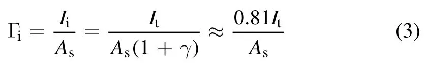

Figure 1.Schematic of the experimental device.
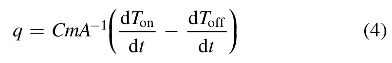
whereAsis the area of the sample holder facing the beam.For the measurement of the heat flux towards the sample holder,the sample holder is replaced by a bolometric probe consisting of a copper plate having the same diameter as the sample holder (diameter 40 mm, thickness 5 mm) and a K-type thermocouple attached to its back side(illustrated in figure 1).Both the copper plate and the thermocouple are embedded in an alumina ceramic substrate and the copper plate is also negatively biased at −100 V.To determine the heat flux towards the sample holder, the time derivatives of the thermocouple temperature at the bolometer during both the heating(plasma on)and the cooling(plasma off)cycles are measured.Then, the heat fluxqcan be approximately obtained through the equation
3.Results and discussions
3.1.Exposure condition modification with respect to the magnetic field intensity
Heat fluxqmeasured by the bolometer and ion fluxΓiobtained from the sample holder current as a function of upstream coil currentIupare shown in figure 2.Here, the downstream coil currentIdownwas not applied(Idown= 0 A).It is found that forIuplower than 40 A(magnetic field in the antenna zoneB0< 500 G),the sample holder is under a low-flux exposure condition withq≈ 1 W cm−2andΓi< 1021m−2s−1.Further increasingIupto 60 A(B0> 700 G),the source transforms into a high-flux mode withq> 10 W cm−2andΓiup to 1022m−2s−1.This flux jump can be attributed to the mode transition from H mode to W mode with a more efficient power absorption mechanism by resonant wave-coupling [8].
People often say there is a special chemistry between a father and a son. He came back into the kitchen just as I was about to storm out. He had loosened8 his tie and rolled up the sleeves of his shirt – ready to relax. In his right hand was the old apron.

Figure 2.Heat flux q and ion fluxΓi measured with applied Iup from 10 to 120 A and Idown at 0 A.The magnetic field strength B0 in the antenna zone (z = −10 cm) is about 12 G A-1.
An interesting phenomenon we found in figure 2 is the decline of heat and ion fluxes towards the sample holder with increasingIupin H mode withIup≤ 40 A.For a more in-depth study, the radial profiles of plasma densityn0and electron temperatureTein front of the sample holder were measured with a Langmuir probe at a location ofz= 19 cm with differentIup(10 A,20 A,30 A and 40 A),as shown in figure 3(a).ForIup= 10 A,the radial ion density profile shows an on-axis peaked structure with a beam radius of 3.7 cm(defined by the half-value width).AsIupincreases from 10 A to 30 A and then to 40 A, typical ‘hollow-like’ structures with peaks occur offaxis at the radial positionr≈ 3 cm, along with an increasing degree of the hollowness(defined by the ratio of off-axis peak density to central density) and a decline of on-axis plasma density from1.1 × 1017m-3to 7.2 × 10¹⁶m-3.The radial profiles ofTealso show a ‘hollow-like’ structure with off-axis peaks located in nearly the same position as the density off-axis peaks (r≈ 3 cm).

Figure 3.Radial profiles of plasma density n0 and electron temperature Te measured at z = 19 cm with applied Iup from 10 to 40 A in H mode(a) and with applied Iup from 60 to 120 A in W mode (b). Idown is fixed at 0 A.
According to [14, 15, 18], the formation of the ‘hollowlike’ structure downstream of the source in H mode can be explained as follows: in the insulating source tube with an external magnetic field, electrons heated by the RF antenna current will be radially confined to the skin layer near the inner tube wall.Instead of electron-neutral collisions, some of the energetic electrons will be transported along the LMFL from the side edge of the tube into the expansion chamber,causing extra ionization off-axis downstream of the source.As the magnetized ions are restricted near the LMFL, a‘hollow-like’ density distribution is formed.To understand the role of the upstream magnetic field in the degree of hollowness,the electron Larmor radiusρeand ion Larmor radiusρiat an axial location ofz= 19 cm for differentIupwere calculated and are listed in table 1.The calculated electron Larmor radiusρeis much smaller than the chamber radius(8 cm), which confirms that the electrons here are totally magnetized.The energetic electrons from the upstream source tube will be radially confined near the radial location of the LMFL atr≈ 3 cm(z= 19 cm),as shown in figure 4(b)(pink line).For lowIup= 10 A, the ion Larmor radiusρiis about 4.75 cm, which is nearly half the chamber radius.In a such case, although energetic electrons can cause extra ionization off-axis near the LMFL, some of those weakly magnetized ions will be lost quickly in the radially outer side toward the chamber wall.Moreover, asρiis larger than the radial location of the LMFL, the remaining ions will be transported to the radially inner side, forming an on-axis peaked structure.ForIup= 20 A,ρiis about 2.38 cm, which is close to theradial location of the LMFL.Here, due to the greater magnetization of the ions, the density is relatively flattened radially.Further increasingIupto 30 A and then to 40 A,asρibecomes much smaller, highly magnetized ions are confined near the LMFL and the density distribution shows a‘hollowlike’ structure.The increasing degree of hollowness of the plasma density profile can explain the decline of measuredqandΓiwith risingIup, because the sample holder and bolometer with a small radius (2 cm) is located in the hollow region of the beam, as labeled in figure 3.

Table 1.Ion and electron Larmor radii for different Iup in the diffusion chamber at z = 19 cm where Langmuir probe measurements are performed (Idown = 0 A).
The radial profiles ofn0andTein W mode at the locationz= 19 cm were also investigated with differentIup(60 A,80 A,100 A and 120 A),as shown in figure 3(b).The electron temperature does not change much with variableIup.It is approximately 3.3 eV in the axis with a gradual decline of about 1 eV to the edge of the plasma.Unlike in H mode, the radial density distribution in the W mode presents a typical on-axis peaked structure.Because the transition from H to W mode is always accompanied by a substantial increase in the axial component of the RF wave field in the bulk of plasma,we can expect a corresponding current which can cause ohmic heating inside the plasma column (wave-resonant heating of electrons) and bring about a centrally peaked density profile[9].It is shown that the plasma beam under a stronger upstream magnetic field has a higher plasma density than the one under weaker field,which matches well with the results in figure 2 and can be explained as follows.For helicon plasma with a radial density gradient, a potential well can be set for radially localized helicon (RLH) waves and the dispersion relation for RLH waves can be written as [25]:
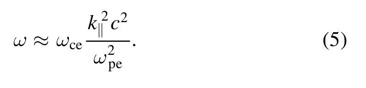
Here, the electron cyclotron frequencyωceand the plasma frequencyωperelate to the magnetic fieldB0and the densityn0, respectively.k‖is the wave-vector component parallel to the magnetic field,which can be estimated byπ L,/ whereLis the characteristic length of the plasma.Thus,for a fixed wave frequencyω, the densityn0is approximately proportional to the magnetic fieldB0.Assuming that the wave frequencyωis approximately equal to the driving frequency of the RF power source (13.56 MHz), for a magnetic field of 1300 G(Iup= 100 A), the plasma density derived from equation (2)is about 5.2 × 10¹⁸m-3, which matches well with the value measured by the Langmuir probe, 4.0 × 10¹⁸m-3.It should be noted that the presence of a sufficiently high and diverging static magnetic field may lead to the formation of a currentfree double layer (CFDL) [26].A CFDL can affect the downstream plasma performance since it can not only accelerate the ions but also decelerate the energetic electrons upstream of the CFDL[27];therefore,further experiments are needed to verify whether a CFDL exists in this device or not.
3.2.Modification of exposure conditions with respect to the geometry of the LMFL
For further verification of the important role that the LMFL plays in plasma radial distribution and exposure conditions,the LMFL geometry was specially modified by tuning the downstream coil currentIdown.For H mode,Iupwas fixed at 30 A,whileIdownvaried from 0 to 45 A.For W mode,Iupwas fixed at 100 A, whileIdownvaried from 0 to 150 A.Those values can bring about a flux tube geometric transition from expansion to uniformity and then to convergence.Axial magnetic field profiles and the flux tube mapping of the LMFL with differentIdownin both H and W modes are shown in figures 4(a)and(b),respectively.Also,the locations of the antenna, upstream and downstream coils, as well as the sample holder are labeled.
The influences of downstream magnetic field on heat fluxqand ion fluxΓitowards the sample holder in H and W modes are shown in figures 5(a) and (b), respectively.In H mode,measurements were performed with fixedIupat 30 A and differentIdownat 0 A,15 A,30 A and 45 A,while in W mode,measurements were performed with fixedIupat 100 A and differentIdownat 0 A, 50 A, 100 A and 150 A.It was found that, increasing the downstream magnetic field (Idown) could significantly increase the heat and ion fluxes towards the sample holder.The radial profiles of plasma densityn0and electron temperatureTein front of the sample holder atz= 19 cm were measured for a better understanding of this phenomenon.

Figure 4.(a) Calculated axial profiles of the applied magnetic field.For H mode (dashed lines), Iup is fixed at 30 A, with different Idown from 0 to 45 A.For W mode(solid lines),Iup is fixed at 100 A,with different Idown from 0 to 150 A.(b) Mapping of the LMFL.The positions of the antenna, coils and sample holder are also marked.
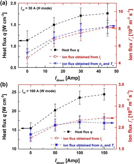
Figure 5.Heat flux q and ion fluxΓi measured (a) in H mode with applied Idown from 0 to 45 A and Iup at 30 A and(b)in W mode with applied Idown from 0 to 150 A and Iup at 100 A.The ion flux estimated from n0 and Te profiles in figure 6 is also plotted (blue asterisks).
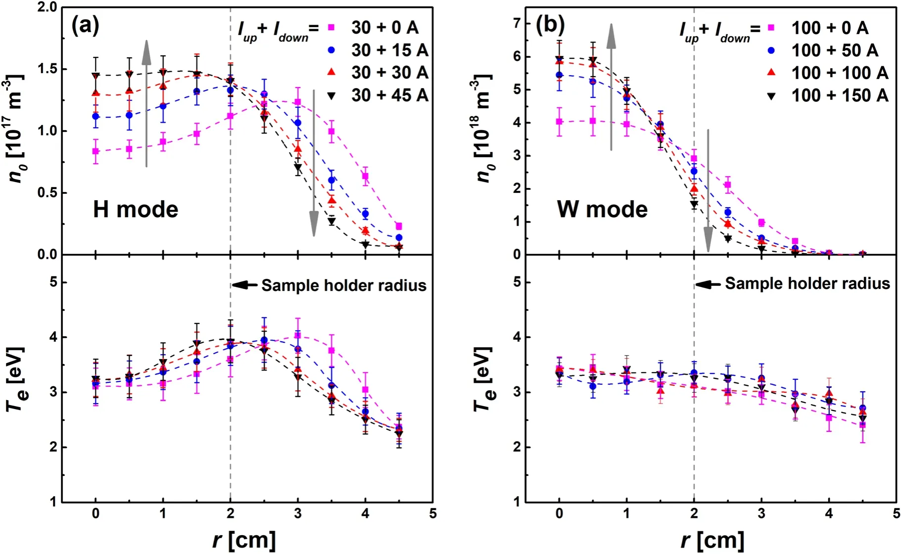
Figure 6.Radial profiles of plasma density n0 and electron temperature Te measured at z = 19 cm(a)in H mode with fixed Iup at 30 A and different Idown from 0 to 45 A and (b) in W mode with fixed Iup at 100 A and different Idown from 0 to 150 A.
Figure 6(a)shows the radial profiles of plasma densityn0and electron temperatureTeobtained from the Langmuir probe at an axial location ofz= 19 cm in H mode with differentIdown(0 A, 15 A, 30 A and 45 A) and fixedIup(30 A).As already discussed above,forIdown= 0 A with a diverging LMFL,both the radial profiles ofn0andTeshow a typical ‘hollow-like’ structure with the peak occurring offaxis near the position of the LMFL atr≈ 3 cm.AsIdownincreases from 0 to 30 A, off-axis peaks for both ion density and electron temperature shift towards the radially inner side,which matches well with the inner shift of the LMFL atz= 19 cm,as shown in figure 4(b).This is consistent with the formation mechanism of the ‘hollow-like’ structure mentioned above.With the contraction of the LMFL, more energetic electrons will be converged to the beam center,causing an additional ionization and an increase in the center density.Further increasingIdownto 45 A, the ‘hollow-like’structure disappears and the plasma shows a more uniform radial density distribution with a higher central density.
Next, for W mode operation the radial profiles ofn0andTeat an axial location ofz= 19 cm are shown in figure 6(b).Iupis fixed at 100 A, whileIdownvaries from 0 to 150 A.The profile in the stronger downstream magnetic field with higherIdownshows a higher plasma density in the central region(r< 1.5 cm)of the plasma column and a lower density in the outer region (r> 1.5 cm).The transition location atr= 1.5 cm nearly coincides with the radius of the source tube.This indicates that, with suppressed plasma cross-field diffusion by the stronger magnetic field and the inner contracted LMFL, less plasma will be radially lost from the plasma column.A similar plasma constriction phenomenon has also been observed by Takahashiet alin a convergent magnetic field downstream formed by attaching a permanent magnet to the back of the substrate, which can significantly increase the central density of the beam[28].In addition,this configuration created by a combined use of solenoid and permanent magnet provides us with a more convenient method to enhance plasma irradiation to the target.In our case, although a higher central density can be achieved with increasingIdown, the decreasing beam diameter from 2.5 to 1.6 cm will limit the size of samples suitable for plasma irradiation experiments.Unlike plasma density, the electron temperature is almost constant with variableIdown, which is nearly 3.3 eV in the center and declines gradually to about 1 eV at the edge of the beam.In addition,there is evidence that changing the downstream magnetic field can affect the wave field propagation and thus the plasma performance[29,30].To investigate the degree to which it can influence the plasma exposure conditions in our system, further efforts are urgently needed to measure the wave field, especially the development of a B-dot probe.
Moreover,in order to check the consistency between the data obtained from the Langmuir probe and the sample holder, ion flux towards the sample holder is estimated by using then0andTeprofiles in figure 6.Assuming that ion flux Γiis conserved in the sheath, then it can be expressed as follows [31]:
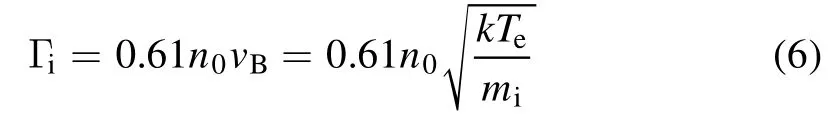
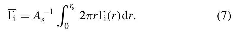
Herers=2 cm is the radius of the sample holder.In figure 5,Γicalculated fromn0andTeis illustrated as a function ofIdownin both H and W modes, which matches well with the ion flux estimated from the sample holder current.
4.Summary and conclusion
In this work, the dependence of magnetic field geometry on plasma exposure conditions downstream in the diffusion chamber has been investigated in helium plasma produced by a helicon antenna.Due to the transition from H to W modes, a flux jump of ions and heat of an order of magnitude can be found with increasing upstream magnetic field.In H mode with increasing upstream magnetic field, a decline of ion and heat fluxes into the sample holder is found,which is attributed to the change in plasma radial density profile from being ‘center peaked’ to ‘hollow-like’ as more magnetized ions are confined near the LMFL with smaller ion Larmor radii.In W mode,the density profile presents a typical on-axis peaked structure and the rise of the upstream magnetic field can dramatically increase the fluxes of ion and heat, which matches well with the dispersion relation for RLH waves.Furthermore, the effect of LMFL geometry on the exposure conditions was investigated.By increasing the downstream magnetic field, a geometric transition of LMFL from expansion to uniformity and then to convergence was achieved.In H mode with the contraction of LMFL, the off-axis peaks of both plasma density and electron temperature profiles shift radially inwards, bringing about a beam with better radial uniformity (a lower degree of hollowness)and higher ion and heat fluxes.In W mode,plasma crossfield diffusion is suppressed by the increasingIdown, and the beam shows a higher density in the center and a lower density on the edge along with a decrease in diameter.
To sum up, this work not only gives us an in-depth understanding of the role played by the magnetic field geometry in the plasma performance downstream in the diffusion chamber, but also presents an innovative method for plasma beam optimization with better radial uniformity and tunable ion and heat fluxes by modifying the magnetic field.Moreover, in further studies, more attention should be devoted to the current-free double layer and wave field structure since they have a potential impact on the irradiation conditions.
Acknowledgments
This work is supported by National Natural Science Foundation of China (No.11975163) and the Shenzhen Clean Energy Research Institute.
猜你喜欢
杂志排行

Plasma Science and Technology的其它文章
- First results of negative ion extraction with Cs for CRAFT prototype negative beam source
- Manipulation and optimization of electron transport by nanopore array targets
- Modulational instability of the coupled waves between fast magnetosonic wave and slow Alfvén wave in the laser-plasma interaction
- Dense positrons and γ-rays generation by lasers interacting with convex target
- Linear gyrokinetic simulations of reversed shear Alfvén eigenmodes and ion temperature gradient modes in DIII-D tokamak
- Design and performance study of a gas-Cherenkov detector with an off-axis parabolic reflector for inertial confinement fusion experiments