Research on the real-time signal conditioning method for dispersion interferometer in HL-2M
2020-11-10WeiZHANG张伟TongyuWU吴彤宇JianZHANG张健ZejieYIN阴泽杰andYanZHOU周艳
Wei ZHANG(张伟),Tongyu WU(吴彤宇),Jian ZHANG(张健),Zejie YIN(阴泽杰) and Yan ZHOU(周艳)
1 College of Electronics and Information,Hangzhou Dianzi University,Hangzhou 310018,People’s Republic of China
2 State Key Laboratory of Particle Detection and Electronics,University of Science and Technology of China,Hefei 230026,People’s Republic of China
3 Department of Modern Physics,University of Science and Technology of China,Hefei 230026,People’s Republic of China
4 Southwestern Institute of Physics,Chengdu 610041,People’s Republic of China
Abstract
Keywords:signal conditioning,electron density,dispersion interferometer,HL-2M
1.Introduction
Recently,HL-2M tokamak,upgraded from HL-2A tokamak,is under assembly progress in Southwestern Institute of Physics(SWIP)[1].The mission of HL-2M is to undertake plasma experiments under high-performance plasmas.The plasma electron density is one of the components of the fusion triple product.The density measurement is an indispensable part in the magnetically confined fusion plasma diagnostics.Since the electron density measurement system is one of the real-time feedback control systems,the accuracy and stability of the system are particularly crucial.
Far-infrared(FIR)laser interferometers have been regarded as an effective diagnostic tool dedicated to the plasma electron density measurement[2].An heterodyne interferometer system has been deployed in HL-2A[3-6].It is based on the methanoic acid laser whose wavelength is 432.5 μm.The long wavelength laser interferometers are prone to occur more fringe jumps which is a serious problem in high-performance plasma measurements[7,8].Therefore,a new dispersion interferometer(DI)is proposed with 10.6 μm laser[9-11].The DI is much more stable than heterodyne interferometer because of the shorter wavelength of the laser[12,13].
However,the intensity of the signal laser is weak near the detectors because of the complexity of DI light path.To process a valid measurement,a high sensitive detector is used for optical-to-electrical conversion.Thus,the intensity of the detected signal is easily affected by environmental factors.For instance,mechanical vibration,light path changes,and plasma refraction effect during the experiment will distort the signal amplitude.The insufficient signal amplitude results in worse signal-to-noise ratio(SNR)and lower accuracy.This is a hidden danger for the feedback and control in tokamak.In order to solve this problem,an amplifier with adjustable gain is used for HCOOH laser interferometers in HL-2A.It works well in some situations caused by effects that change slowly such as the attenuation of optical paths and cables[14].But it cannot deal with mechanical vibration and plasma refraction effects occurred during the plasma discharge.
In this study,we focus on improving the accuracy of the DI system and proposed a real-time signal conditioning(RSC)method.It replaces traditional analog circuits with real-time,low latency feedback circle implemented on FPGA.It is able to adjust the amplitude changes caused by mechanical vibration and plasma refraction effects.After the RSC module outputs the signal with a sufficient amplitude,a synchronous demodulation module extracts the electron density signal to achieve real time and high temporal resolution measurements.

Figure 1.Schematic diagram of the dispersion interferometer in HL-2M.
2.Basic principle of the DI and demodulation system
The principle of the DI system in HL-2M[7]is shown in figure 1,for more details,see the[11].
The beam from the CO2laser is focused on a nonlinear crystal to generate a second harmonic beam.The beams propagate through the HL-2M plasma and get the information of the electron density.A photoelastic modulator(PEM)is placed after the plasma to phase modulate the second harmonic beam and the modulation angular frequency is ω0.Then,another nonlinear crystal generates a new second harmonic beam from the fundamental wave.There is a filter before the detector to ensure that only the beams with frequency of 2ω can reach the detector.The beams interfere with each other and the interference intensity is detected as

where ω is the angular frequency of the laser.is the line-integrated electron density.A is the direct current component.ρ0is the amplitude of phase modulation by PEM.The term A is cut off by an analog filter,because it has no contribution to measurement.Thus,the digital signal from ADC is

The signal I(t)contains many harmonic components,and n is a positive integer which represents the order of each harmonic component.Since the base frequency ω0is 50 kHz,I(t)contains components such as 50,100,and 150 kHz.The amplitudes with frequencies of 50 and 100 kHz are

J1and J2refer the Bessel function of the first kind.By setρ0to 1.3rad,the value ofJ1( 2ρ0)is equaltoJ2( 2ρ0).Then,the densityisderived from equations(4)or(5):

A synchronous demodulation system has been developed for HL-2M to get the amplitudes with the frequencies of 50 and 100 kHz[15].After the input signal I(t)passes through a high-pass filter,it is mixed with the reference signal output by PEM.Therefore,the specified frequency components are moved to direct current component.There are some digital low-pass filters after the mixer to recover the amplitudes with the frequencies of 50 and 100 kHz.Finally,we obtain the target signals I2/2 and−I1/2.More details about the synchronous demodulation algorithm are described in[16].
3.The RSC method
Signal with insufficient amplitude will lead to low measurement accuracy because of the low SNR.On the other hand,the digital signal will be cut off if the signal amplitude exceeds the ADC dynamic range.The cut-off distortions have more impacts on the measurement accuracy.Due to mechanical vibration and plasma refraction effects,the signal amplitude changes rapidly in plasma discharge experiments.In order to stabilize the signal amplitude during plasma discharge,the signal conditioning method should adjust the amplitude in real time.We proposed a RSC method based on negative feedback.
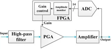
Figure 2.The block diagram of the real-time signal conditioning method for DI.
Figure 2 shows the block diagram of the RSC method.First,the signal from the interferometer passes through a high-pass filter to eliminate the low frequency component.The baseline variation is caused by environmental factors and the frequency of the variation is lower than 1 kHz.So the cutoff frequency of the filter is set to 1 kHz.The RSC method cannot make full use of the dynamic range of the ADC without the filter.Second,the signal from the filter feeds into a programmable-gain amplifier(PGA).The PGA is the main module of the RSC to implement the signal conditioning.Third,the output of PGA is fanned out by an amplifier to drive the ADC and the synchronous demodulation module.Fourth,the ADC transfers the analog signal to digital data.Finally,the FPGA monitors the signal amplitude and adjusts the gain of the PGA to maintain the suitable signal amplitude[17-19].The whole loop delay is less than 1 μs.
There are some amplitude estimation methods in recent reports.Reference[20]focused on the amplitude estimation of a distorted sine wave by a windowed FFT algorithm.Nevertheless,it is difficult to get the amplitude of the signal I(t)with the FFT algorithm because there are many harmonic components in I(t).Hence,a digital envelope detection algorithm(DEDA)is proposed to replace analog circuits.It can get the amplitude in real time with low delay and low calculation resource consumption.
Figure 3 shows the basic principle of the analog envelope detection circuit.The relationship between the output and input voltage can be written as


Figure 3.The basic principle of the analog envelope detection circuit.
The discrete forms of equations(7)and(8)are provided as

where the ReLU is an activation function called rectified linear unit function.The time interval Δt is 0.1 μs,which corresponds to the sample rate of the ADC.The time constant τ=RC determines the rate at which the RC circuit discharges.Considering that the frequency of the signal is greater than 50 kHz,we choose a time constant of 0.25 ms which ensures the real-time performance of the method.
The amplitude is estimated from the envelope calculation by DEDA.Accordingly,we can establish a negative feedback loop by setting the upper and lower thresholds.The FPGA decreases the gain of the PGA by 1 dB when the envelope exceeds the upper threshold.In contrast,the FPGA increases the gain of the PGA by 1 dB when the envelope drops below the lower threshold.Considering the latency of the feedback loop,the envelope monitoring process will be suspended after the gain adjustment signal is sent.The upper and lower thresholds are set to 90% and 72% of the ADC’s dynamic range,respectively.Therefore,the output from the RSC module will fall into a suitable range,as long as the gain adjustment does not exceed the upper and lower limits that the PGA can adjust.

Figure 4.The block architecture of the synchronous demodulation system with RSC.
4.Hardware implementation
Based on the PCI Express eXtension for Instrumentation(PXIe)platform,a new PXIe RSC module has been designed for the synchronous demodulation system in HL-2M.As shown in figure 4,the DI data acquisition(DAQ)system with RSC consists of a PXIe RSC module,PXIe demodulation modules and a PXIe system controller.There are two independent DI channels in the system.
4.1.PXIe RSC module
The PXIe RSC module is a plug-in board which implements the RSC method.The module contains two independent DI channels with ultra-low crosstalk.
A first-order RC high-pass filter is employed in each channel to filter out the low frequency component.The signal is amplified or attenuated by the PGA after passing through the filter[21,22].This module requires a wide reconfigurable gain range,a flat frequency and phase response to maintain low distortion.We choose the PGA870 manufactured by Texas Instruments as the critical part in the PXIe RSC module.It is a wideband PGA with low distortion and low noise for high-speed systems.It is ideally suited for RSC applications.The configurable gain range is−11.5 to 20 dB,and the gain settling time is less than 5 ns.These parameters meet the system requirements.
The signal is sampled by the ADC after passing through the driver amplifier.The ADC is a 14 bit,105 Msps,lowpower dual-channel LTC2284.The RSC method is implemented in the Xilinx Spartan-6 high-speed FPGA.It also realized some other functions like DEDA and data uploading.The on board FPGA communicates with the PXIe controller through PXIe bus.
4.2.PXIe demodulation module
The signals from the PXIe RSC module are transferred to the PXIe demodulation modules which are the main components of the DAQ system.The PXIe demodulation module implements the synchronous demodulation algorithm described in section 2.To correct the fringe jump errors,the real-time phase jump process algorithm is applied after the Arc tangent operation in equation(6).It extends the phase measurement range of synchronous demodulation[23].Then the phase is multiplied by a factor to get the electron density.The modules use a fast digital-to-analog converter to transfer the electron density data to analog signal for low latency feedback in HL-2M.At the same time,the electron density data are uploaded for storage.
4.3.PXIe controller
The PXIe controller is a PXIe-8135 manufactured by National Instruments.It supports real-time operating system,which reduces the delay of the control system.The controller obtains the output of DEDA through PXIe bus for stability analysis.The data can be used to optimize the optical layout and interferometer signals.Meanwhile,the electron density measurement data are transferred to the controller for saving locally.It receives control commands from the central control system of HL-2M and uploads the experiments data to the remote storage server.
5.Performance evaluation
5.1.Test experiments
To test the performance of the RSC method,we generated an artificial interferometer signal distorted by mechanical vibration and plasma refraction effects.It is assumed that the plasma electron density rises linearly.According to equation(1),the artificial waveform can be expressed as

where ρ0=1.3.Fm,corresponding to the PEM phase modulation angular frequency ω0,is 50 kHz.The model density term is 2πfnelt,which corresponds to the linearly rising electron density.The frequency of the model density term is set to fnel=10 kHz.[sin(2πFAMt)+1.2]is the distortion term affected by the environment.To test the function of the RSC method,the frequency of the distortion term is set to FAM=0.5 kHz and the maximum value of the term is set to 11 times the minimum value.
The artificial waveform is downloaded to an arbitrary waveform generator whose model is AFG3102C.It is used to generate the analog signal to imitate the interferometer signal.Figure 5 shows the artificial waveform with FAM=0.5 kHz and the envelope detection curve.The envelope detection curve was measured by using the amplitude estimation methods.We can see that the curve outlines the signal amplitude with high precision.
The artificial waveform was fed into the PXIe RSC module.Figure 6 shows the output from the PXIe RSC module with automatic gain adjustment.They show that the RSC method can follow the signal amplitude variation and maintain the amplitude in the suitable range.
The PXIe demodulation module measured the linearly rising electron density directly from the artificial waveform.The errors between the model density(2πFnelt)and the measured density are shown in figure 7(a).In contrast,figure 7(b)shows the errors of the DI system using the RSC module.The maximum error without the RSC module is up to 6×10¹⁸m−2while the error with the RSC module is better than 2×10¹⁸m−2.The result indicates that the RSC method can improve the measurement accuracy in complex environments.

Figure 6.The output from the PXIe RSC module and the corresponding envelope detection curve.

Figure 7.(a)The errors between the model density and the measured density without RSC.(b)The errors between the model density and the measured density with the RSC.
5.2.Application experiments
An experiment of the RSC method for DI has been successfully carried out in HL-2A at the SWIP,China.The probe beam path in HL-2A vacuum chamber is tangential chord to increase the line-integrated density.
Two synchronous demodulation systems were used to verify the performance of the RSC method.One of the system was directly fed with the interferometer signal and the input signal of the other system is processed by the PXIe RSC module.In shot 31124 of HL-2A,the raw ADC data of the systems with and without the RSC module are shown in figures 9 and 8.
In figure 8,we can see the low signal amplitude and the large baseline variation around 35 ms,which is difficult for synchronous demodulation.In figure 9,the signal from the PXIe RSC module is sufficient to measure the electron density.
The density measurement results of the two systems for DI have been obtained and compared with the results from the existing FIR HCOOH laser interferometer.Figure 10 shows the electron density curve of the system without the RSC method.The accuracy is particularly low and the measurement is dangerous for tokamak real-time feedback.
Figure 11 shows the electron density curve of the system with the RSC method.The accuracy improvement is remarkable.The interferometry chord of the heterodyne interferometer is radial which is different from the probing chord of the DI.Considering the difference in the direction of the probing line,the DI curve is slightly different from the heterodyne interferometer curve.Nevertheless,the curve trends between the DI and the FIR are still highly consistent.

Figure 8.The raw ADC data of the systems without the RSC module.

Figure 9.The raw ADC data of the systems with the RSC module.

Figure 10.Measurement results of DI without the RSC method and the far infrared laser heterodyne interferometer in HL-2A.

Figure 11.Measurement results of DI with the RSC method and the far infrared laser heterodyne interferometer in HL-2A.
6.Conclusion
This paper describes the study of a RSC method for DI on HL-2M tokamak.As one of the key subsystems,the DI system supports signal conditioning,DAQ,processing and feedback control.The RSC method is based on DEDA and negative feedback loop.It can maintain the sufficient signal amplitude in real time with low delay and low calculation resource consumption.The RSC method is robust in complex tokamak devices.It can improve the density measurement of most shots.In harsh environments,the maximum error of the line-integrated density measurement is still better than 2×10¹⁸m−2with the RSC method.Both simulation and application results reasonably reflected the stability of the DI system with the RSC method.The results demonstrate the capability of the RSC method to improve the accuracy of the DI system in complex environments.
ORCID iDs
杂志排行
Plasma Science and Technology的其它文章
- The effect of resonant magnetic perturbation with different poloidal mode numbers on peeling-ballooning modes
- Soft landing of runaway currents by ohmic field in J-TEXT tokamak
- Numerical simulations of the wavefront distortion of inter-spacecraft laser beams caused by solar wind and magnetospheric plasmas
- Effect of insulating oil covering electrodes on the characteristics of a dielectric barrier discharge
- Numerical study on the modulation of THz wave propagation by collisional microplasma photonic crystal
- Study of partial discharge characteristics in HFO-1234ze(E)/N2 mixtures