RAN Centric Data Collection for New Radio
2019-12-30GAOYinLIDapengHANJirenLIUZhuangLIUYang
GAO Yin LI Dapeng HAN Jiren LIU Zhuang LIU Yang


Abstract: Self?organizing network (SON) and minimization of driver tests (MDT) are functions designed for Long Term Evolution (LTE) system. SON is designed for network deployment by automatic configuration. MDT is designed for network performance evaluation by automatic signalling procedure. However, these functions do not support new features in new radio (NR) access technology, e.g., multiple radio access technology (RAT)?dual connectivity (MR?DC), central unit?distribute unit (CU?DU) split architecture, beam, etc. Therefore, how to support these features is a challenge for the industry. This paper provides analysis for these problems and provides the summary of SON/MDT functions progress in 3GPP. The analysis includes sub functions such as inter/intra system mobility robustness enhancement, inter/intra system mobility load balance, measurement qualities and mechanism of MDT, energy saving mechanism and procedure, RACH procedure optimization, PCI selection optimization, coverage and capacity optimization, and quality of service (QoS) monitoring mechanism. In addition, this paper also provides an initial thought on artificial intelligence (AI) algorithms applied to SON/MDT functions in NR, so called Smart Grid.
Keywords: NR; SON; MDT; data collection
DOI: 10.12142/ZTECOM.201903005
http://kns.cnki.net/kcms/detail/34.1294.TN.20190924.1129.004.html, published online September 24, 2019
Manuscript received: 2019?07?31
1 Introduction
elf?organizing networks (SON) and minimization of driver tests (MDT) have been introduced in Long?Term Evolution (LTE) system [1] to support deployment of the system and performance optimization. From the field application, benefits have been identified when performing network planning and self?optimization by applying SON and MDT features. Its worthy to investigate whether to introduce these mature technologies to achieve better performance in new radio (NR) system [2], [3]. In May 2019, 3GPP completed a study project for this purpose with the name “Study on RAN?Centric Data Collection and Utilization for LTE and NR” [4], [5]. In addition, a new working project “New WID on support of SON and MDT for NR” [6] has been started from middle of 2019. In this paper, we analyze SON and MDT features and introduce the corresponding standard progress in 3GPP. In addition, this paper also provides the initial thought on artificial intelligence (AI) algorithms applied to SON/MDT functions in NR, so called Smart Grid. At the end of the paper, conclusions and future work are proposed.
2 Overview
The first SON features, physical cell identifier (PCI) allocation and automatic neighbor relations (ANR) [1], were introduced in early version of LTE. Success of these two features encouraged further study on the topic and resulted in a Rel?9 work item that eventually enabled three SON features: mobility robustness optimization (MRO) [1], mobility load balancing (MLB) [1] and random access channel (RACH) optimization [1]. MRO and MLB have been turned out to be the key enablers of LTE and further enhanced in the following releases to match the increasing LTE complexities. Besides ANR, MRO, MLB and RACH optimization, other features enabling particular aspects of network self?optimization have been discussed and enabled in separate studies or working projects, including MDT [7], energy saving (ES) [1], interference cancellation (ICIC, eICIC) [1], etc. These SON features are performed based on the statistic of massive data from network and user equipment (UE), which can be regarded as the pioneers of data usage in Radio access network (RAN). How to support these features have also been discussed in the related study projects. For example, introducing SON and MDT features in NR should take into account new architecture such as multiple radio access technology (RAT)?dual connectivity (MR?DC) architecture, central unit?distribute unit (CU?DU ) split architecture, beam level resource management, RRC?INACTIVE state, etc[8], [9].
3 SON and MDT Features and Evolution in 3GPP
3.1 Mobility Robustness Optimization
MRO aims at detecting and enabling correction of mobility related problems which will deteriorate user experience and waste network resources. In LTE, there are three kinds of problems, i.e., connection failure due to intra?LTE or inter?RATI radio access technology) mobility, unnecessary handover to another RAT, and inter?RAT ping?pong.
With the deployment of NR, as shown in Fig. 1, an evolved Node B (eNB) could be connected with Evolved Packet Core (EPC) and 5G Core (5GC) at the same time. The handover between two eNBs may be either intra?system or inter?system. Similarly, for the handover between eNB and gNodeB (gNB), it could be also either intra?system or inter?system [10].
According to Fig. 1, the handover procedures in NR include the following four types:
· Intra?NR mobility, i.e., handover between gNBs via Xn interface
· Intra?system/inter?RAT mobility, i.e. handover from gNB to eNB 2 via Xn interface
· Inter?system/inter?RAT mobility, i.e., handover from gNB to eNB 1 via S1 and NG interfaces
· Inter?system/intra?RAT mobility, i.e., handover from eNB 1 to eNB 2 via S1 and NG interfaces.
In NR, the above mobility related problems still exist. Just as shown in Fig. 1, the radio link failure report and handover report could be transferred over Xn, S1 and NG interfaces.
There are three kinds of connection failure to intra?system or inter?system mobility, i.e., too late handover, too early handover, and handover to a wrong cell. To detect these events, the RRC procedures as radio link failure (RLF) indication and handover report can be used. With the report from UE, the network side could adjust the handover report related parameters to solve the above mobility failure cases.
For detecting inter?system unnecessary handover, UE continues to evaluate the received measurement report with the coverage and quality condition during the inter?system handover preparation phase. With the measurement report, the RAN node in the source system could sent the inter?system unnecessary handover report to the RAN node in the target system.
For Inter?system ping?pong, the UE history information can be used to detect this event. With the history information, the target new radio?radio access network (NG?RAN) node indicates the occurrence of the potential ping?pong cases to the source NG?RAN node.
In addition to the legacy problems, there are some new issues that need to be studied with the new features and architecture introduced in NR. For example, the new information or measurements should be further defined and collected, such as the beam and slice level measurements. In case of MR?DC, the secondary node (SN) can be configured with Signalling Radio Bearer 3 (SRB3), and can trigger the SN change autonomously. And the SN change related failure can be considered, such as the failure due to too late SN change, failure due to too early SN change, and failure due to change to wrong SN [11]. The RLF report and handover report can be introduced between the main node (MN)/SN and SN. Furthermore, another possible enhancement on MRO is the successful handover report comprising a set of measurement results during the handover. Upon reception of a successful handover report, the receiving node is able to analyze whether its mobility configuration needs adjustment or not in order to optimize the handover procedure [12].
3.2 Mobility Load Balancing
Load balance is another key feature in SON. With this function, the network can distribute the cell load evenly among cells, transfer part of the traffic from congested cell and offload users from one cell or carrier or RAT. This kind of optimization aims to increase system capacity and improve user experience. In addition, this function is able to minimize the human intervention in network management and optimization tasks.
In NR Rel?15, the new architecture and new features are introduced, i.e., CU?DU split and CP?UP separation, the network slicing, MR?DC. All of these features should be taken into account for load sharing and load balancing optimization. Moreover, the features have impact on different interfaces, such as load management over F1 for CU?DU split, load management over E1 for CP?UP separation and load management over X2 and Xn for MR?DC. However, the slice level metrics, such as slice level radio resource utilization, should be further studied to confirm whether they are useful to adjust the cell selection/reselection and handover configuration. As for a wide?band carrier, cell capacity is defined as using the whole capacity of the wide?band carrier for each individual cell belonging to this wide?band carrier [13].
The load related information can be summarized as different level: cell level, beam level and hardware level, as shown in Table 1 [14].
During the Rel?16 normative phase, the following metrics need to be further specified and discussed.
· Composite available capacity (CAC) per cell (downlink (DL)/uplink (UL)), reported via X2, Xn and F1 interfaces
· Cell Level Load (DL/UL/ supplementary uplink (SUL)) reported via X2, Xn, and F1 interfaces
· Transport network layer (TNL) Load reported via X2, Xn, F1, and E1 interfaces
· Beam level load indication
· Hardware load related information
· Per slice/band level reporting
· For EN?DC case, the EN?DC X2 interface shall be enhanced to support load information report from SgNB to MeNB
· Both periodic and event?triggered procedures shall be supported for load information report.
3.3 Minimization of Driver Tests
Driver test technology can check network coverage and improve the quality of service (QoS) of the mobile network. It is a commonly used tool for operators. However, the driver test technology has many limitations, such as high cost and being difficult for many regional operators equipment to reach. The purpose of MDT is to use mobile phones as road test equipment. Multiple use cases for NR MDT have been identified in the study stage in Rel?16. Logged MDT and immediate MDT [7] are recommended to be supported for NR MDT. In NR, these modes also support RRC_INACTIVE state. For tracing [15], the management based mechanism and signaling based mechanism in LTE [16] can be reused in NR MDT, both of which can be either logged MDT or immediate MDT. The MDT data reported from UE and the RAN may be used to monitor coverage problems and to verify QoS in the network. In Rel?16, the WLAN/Bluetooth measurement can be collected to improve positioning accuracy for indoor MDT. In addition to location and time information collection, UE orientation in a global coordinate system can be collected in MDT if the information is available. The mentioned use cases, including coverage optimization, QoS verification and WLAN/Bluetooth measurement of LTE, are taken as the baseline of NR. Take the QoS verification function as an example. When UE is in RRC_CONNECTED state, the network retrieves the UE measurements of on?going traffic and uses such information to decide which area is the hot spot and lack of capacity.
Similar as in LTE, the RAN energy saving function in NR allows, for example in a deployment where capacity boosters can be distinguished from the cells providing basic coverage, energy consumption optimization to enable a NR cell to provide additional capacity. In addition, new architectural features in NR, including CU/DU split and dual connectivity, should also be considered. The Rel?15 3GPP specifications support the following energy saving scenarios: switch?off of NR cells and their reactivation by X2AP signalling from eNB in case of EN?DC; deactivation of capacity cells and their reactivation of neighboring coverage cells by XnAP signalling in NG?RAN; activation of NR cells and their deactivation by gNB?CU via F1AP signalling in the CU?DU separation architecture.
In Rel?16, inter?system inter?RAT energy saving solution is proposed to support efficient 4G and 5G energy saving. Fig. 2 shows one of the prominent scenarios in real deployment for the inter?system inter?RAT energy saving case from operators point of view [17], where Evolved Universal Terrestrial Radio Access Network (E?UTRAN) cell associated eNB and new radio?radio access network (NR?RAN) cell associated gNB are connected to EPC and NGC, respectively, i.e., both eNB and gNB are deployed standalone.
As depicted in Fig. 2, the eNB cells are deployed to provide basic coverage, while the gNB cells boost the capacity. The gNB cell providing capacity booster can autonomously decide to switch off. This decision is typically based on cell load information or commanded by OAM. The eNB providing basic coverage can decide to re?activate the gNB cell on a per?demand basis. Since there is no direct interface between eNB and gNB, energy saving for this case requires S1/NG signalling enhancements. Furthermore, it is up to operators deployment whether inter?system inter?RAT energy saving solution needs to be applied [18], and energy saving solution should not affect user coverage and service.
Furthermore, to evaluate the energy efficiency of RAN node, European Telecommunications Standards Institute (ETSI) Energy Saving (ES) 203 228 (Environmental Engineering (EE); assessment of mobile network energy efficiency) defines the high?level energy efficiency KPI as [EEMN,DV=DVMN/ECMN] [5], in which the data energy efficiency of mobile network is the ratio of the performance indicator (i.e., Data Volume [DVMN]) and the energy consumption ([ECMN]). The data volume per site could be measured by using the Packet Data Convergence Protocol (PDCP) packet data unit Packet Data Unit (PDU). These measurements calculate the UL and DL PDCP data volumes for an aggregated base station or a gNB central unit user plane (CU?UP) in the CP?UP separation architecture. When looking at future cases, it could be plausible to assume that one CU?UP may serve gNB?DUs at different sites. In this case, the measurements could be taken as reference to define new measurements, taken at gNB?DU and measuring the PDCP data throughput incoming to and outgoing from a gNB?DU.
3.5 RACH Optimization
RACH optimization allows network to optimize and select optimized parameters for random access, which mitigates a number of access attempts, mitigates interference among RACH attempts, and/or mitigates uplink interference due to RACH. In LTE system, RACH parameter optimization such as RACH configuration and RACH preamble grouping is performed by UE reported information and by PRACH parameter exchange between eNBs.
In NR, the RACH optimization in LTE could be taken as baseline. RACH optimization is supported by UE reported information and by PRACH parameters of normal UL carrier and SUL carrier exchange over Xn between gNBs and F1 between gNB?CU and gNB?DU.
In addition, In NR system, the NG?RAN node configures the number of SSBs mapped to each PRACH occasion and the number of preambles linked to each SSB. Therefore, the content of the RACH information report possibility comprises of the following [5]:
· SSB indexes and RACH preambles sent on each tried SSB
· Frequency and beam quality of each tried SSB
· Elapsed time from the last measurement prior to the beam selection time
· RACH preambles sent on SUL and NUL
· Fallbacks between contention?based RACH access (CBRA) and contention?free RACH access (CFRA) contention detection indication.
The above RACH information report should also be applied to the SN node for the MR?DC case.
Upon receiving the polling message from the NG?RAN node, UE reports RACH information within a UE information response message. The NG?RAN node takes the RACH report into account, as well as other node related information, in order to optimize the RACH parameters. The setting of RACH parameters that can be optimized includes RACH configuration (resource unit allocation), RACH preamble split, RACH backoff parameter setting, and RACH transmission power control parameter setting.
3.6 Selection of Physical Cell Identifier
PCI is distributed to each cell as a basic feature in SON. With the help of PCI, UE can distinguish different wireless signals from different cells. However, the PCI of different cells could be same because of the limited number of PCI. To minimize the effect of PCI collision, the PCI selection is introduced. In LTE, there are two kinds of PCI assignment algorithms for eNBs PCI selection, i.e., the centralized and distributed algorithms. With the centralized algorithm, the eNB selects the specific PCI value from OAM as its PCI. As for the distributed algorithm, the eNB randomly selects its PCI value from the restricted list of PCIs [19].
In NR, the mechanism of PCI selection in LTE is taken as baseline. For further discussion, the definition of information and the procedures to support PCI conflict discovery and PCI selection should be studied in Rel?16.
As the split gNB architecture, e.g. CU/DU split, is introduced in NR, the PCI assignment algorithm should be evolved based on the new network architecture. The centralized PCI selection can be divided into Option 1a and Option 1b, while the distributed PCI selection can be divided into Option 2a and Option 2b.
· Option 1a: CU detects PCI conflict and indicates to OAM via DU. OAM assigns a new PCI.
· Option 1b: CU detects PCI conflict and indicates to OAM directly. OAM assigns a new PCI.
· Option 2a: CU detects PCI conflict and indicates to DU. DU reassigns a new PCI.
· Option 2b: CU detects PCI conflict and reassigns a new PCI.
The solution to down?selection for the split gNB case will be decided in the normative phase [20].
3.7 Coverage and Capacity Optimization
In RAN, there is a trade?off between coverage and capacity optimization. The increase of the capacity will lead to the degradation of the service coverage, and vice visa. The objective of coverage and capacity optimization (CCO) is to provide the required capacity in the targeted coverage areas and to minimize the interference and maintain an acceptable quality of service in an autonomous way. CCO allows the system to periodically adapt to the changes in traffic (i.e., load and location) and the radio environment by automatically adjusting coverage for the cells that serve a certain area for a particular traffic situation.
In NR, the beam based antenna structures with multi?dimensional RF parameters make it complex to find the mapping between network configurations with target coverage and capacity performance. By using the data collected in the RAN network, e.g. UE measurements, performance measurements, events and other monitoring information, and by taking into account beamforming and massive multiple input multiple output (MIMO)?related information, the operator could identify the coverage and capacity problems, such as coverage holes, weak pilot pollution, overshoot coverage, and DL and UL channel coverage mismatch and further perform coverage and capacity optimization. A coverage hole is an area where the signal level Signal Noise Rate (SNR) of both serving and allowed neighbor cells is below the level needed to maintain basic service, i.e., coverage of Physical Downlink Control Channel (PDCCH). Coverage holes are usually caused by physical obstructions such as new buildings and hills, by unsuitable antenna parameters, or just by inadequate RF planning. UE in a coverage hole will suffer from call drop and radio link failure. In order to identify a coverage hole, for example, RAN network needs to collect necessary measurements with location (e.g. GPS attitude with latitude). Based on these measurements, RAN node can identify the area where the downlink signal cannot fulfill the need for UE. As another example, overshoot occurs when coverage of a cell reaches far beyond what is planned. It can occur as an “island” of coverage in the interior of another cell, which may not be a direct neighbor. Reasons for overshoot may be reflections in buildings or across open water, lakes, etc. UE in this area may suffer call drops or high interference. In order to identify the overshoot issue, RAN network collects measurements with location and with cell information.
For Rel?16 discussion, CCO should focus on the coverage planning. There are two types of network coverage adjustment: long term cell RF parameter tuning and short term cell coverage switching among pre?configurations. The long term cell RF parameter tuning is usually hosted by OAM and relies on UE radio measurements (e.g., Reference Signal Received Power (RSRP), Reference Signal Received Quality (RSRQ), call drops statistics, etc.) that are collected by MDT or performance management function. The short term cell coverage switching is implemented by the NG?RAN node. The dynamic cell coverage configuration change function will be supported by exchanging the cell coverage change information between two neighboring NG?RAN nodes, including the cell coverage state, cell deployment status indicator, and cell replacing information. In the CU?DU split architecture, the gNB?CU should provide relevant information to the gNB?DU, leaving the freedom to the gNB?DU to address such problems [21].
3.8 QoS Monitoring
The QoS requirements specified for particular services (such as Ultra?Reliable and Low Latency Communications (URLLC) services, vertical automation communication services, and Vehicle?to?Everything (V2E) mandate QoS guarantees from the network. However, the network may not be able to always guarantee the required QoS. One reason for this shortcoming is that the latency and/or packet error rates increase due to interference in a radio cell. In this case, it is critical that the application and its server are notified in a timely manner. Hence, the 5G system should be able to support QoS monitoring/assurance for URLLC services, V2X and vertical automation. QoS monitoring function [22]-[30] also needs to consider the impact of CU?DU split architecture. There are two candidate solutions [22], [30] to achieving the requirements of URLLC services:
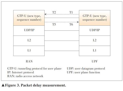
1) Solution 1: Using newly defined packets as monitoring packets.
As shown Fig. 3, a new payload type of QoS monitoring packet (QMP) in the tunnelling protocol for user plane (GTP?U) header (between the user plane function (UPF) and RAN) is introduced. Based on this new QMP, the network can calculate the round trip latency. However, this solution may introduce extra normative work on the specification.
2) Solution 2: Using actual service packets as monitoring packets.
In this solution, the monitoring packet is sampled from the URLLC service packets of UE and UPF based on the measurement period, following the QoS monitoring policy. It is assumed that one?way UL packet delay plus one?way DL packet delay could be regarded equal to the round trip packet delay. Then the network calculates the path delay and provides the whole latency.
The solution to down?selection will be decided in the normative phase.
3.9 Application of Artificial Intelligence
The future 5G corresponds to a highly heterogeneous network, including multiple RATs, multiple cell layers, multiple spectrum bands, different devices and services, etc. Consequently, the overall RAN planning and optimization processes that constitute a key point for the success of the 5G concept will exhibit tremendous complexity. The legacy systems such as 2G, 3G, and4G already started the path towards a higher degree of automation in the planning and optimization processes through the introduction of SON/MDT functionalities.
Nowadays, AI is the science and engineering of making machines as intelligent as humans, which can be applied to optimize communication networks. The inclusion of AI?based tools enables to shift the evolution of the SON paradigm in 5G towards a more proactive approach of exploiting the huge amount of data available and of incorporating additional dimensions coming from the characterization of end?user experience and end?user behavior [31]-[35].
The smart grid method [36] is an example to show how to achieve AI?based 5G SON. The smart grid is obtained by measuring UEs intra?frequency measurement results and then divides the serving cell with multiple grids according to the signalling measurement difference. This is a kind of different space partition method, which is different from the traditional space partition method based on the geographical location. Some AI algorithms can be used to construct the smart grids, e.g., the clustering algorithm.
The NG?RAN node can use these AI algorithms to directly predict the RSRP values of cells on neighboring frequencies for each UE.
We use the load balance use case as an example on how to use smart grids (Fig. 4). Firstly, each grid of the serving cell will be established based on intra?frequency measurement of UE under this serving cell and the grid can be marked with RSRP of the serving cell and other 3 RSRPs of intra?frequency neighbor cells.
After the grids have been established, all the UE measurement reports will be used to setup the footprint information of those grids, e.g., the UE list under this Grid, the inter?frequency neighbor cell list for each carrier (which can be ordered by RSRP). While other possible useful footprint information are not excluded, which depends on the RRM usage.
For load balance case, when the serving cell is overloaded, the RAN node can select some of the UEs under this serving cell, then check the corresponding selected UE via UE ID, and look up the the Footprint information of the Grid which this UE belongs to, there is no need to trigger the inter?frequency measurement towards UE, the RAN node can decide the proper inter?frequency neighbor cell to offload this UE according to the load information of the neighboring cells and the inter?frequency neighbor cell list information of each grid.
The smart grid method can bring lots of benefits to improve the network performance and user experience, e.g., accelerating load balance, improving carrier selection, improving inter?frequency handovers and increasing the user experienced data rate.
4 Conclusions
In this paper, the progress of SON and MDT evolution of NR in 3GPP is analyzed, which include MRO, load balancing and load sharing optimization, MDT, RAN energy saving, RACH optimization, PCI selection, coverage and capacity optimization, Qos monitoring, and application of AI. The function evolution has taken into account NR new features such as MR?DC architecture, CU?DU split architecture, beam level measurements, and measurement sensors. Based on the evolution of these SON and MDT features, better performance can be achieved in NR system.
References
[1] 3GPP. EUTRAN Overall Description: TS 36.300 f.5.0 [S]. 2019
[2] 3GPP. NR and NG-RAN Overall Description: TS 38.300 f.5.0 [S]. 2019
[3] 3GPP. Revised WID on New Radio Access Technology: RP-172109 [S]. 2017
[4] 3GPP. Study on RAN-Centric Data Collection and Utilization for LTE and NR: RP-182105 [S]. 2018
[5] 3GPP. Study on RAN-Centric Data Collection and Utilization for LTE and NR: TR37.816 [S]. 2019
[6] 3GPP. New WID on Support of SON and MDT for NR: RP-191594 [S]. 2019
[7] 3GPP. Minimization of Drive Tests (MDT): TS 37.320 [S]. 2019
[8] GAO Y, HAN J R, LIU Z, et al. General Architecture of Centralized Unit and Distributed Unit for New Radio [J]. ZTE Communications, 2018, 16(2): 23-31. DOI: 10.3969/j.issn.1673-5188.2018.02.005
[9] HUANG H, LIU Y, LIU Z, et al. Mechanism of Fast Data Retransmission in CU?DU Split Architecture of 5G NR [J]. ZTE Communications, 2018, 16(3): 40-44. DOI: 10.19729/j.cnki.1673-5188.2018.03.007
[10] 3GPP. Discussion on Mobility Robustness Optimization in 5G System: R3-190289 [S]. 2019
[11] 3GPP. SN Change Failure in Case of MR-DC: R3-192255 [S]. 2019
[12] 3GPP. Discussion on Mobility Robustness Optimization in 5G system: R3-193186 [S]. 2019
[13] 3GPP. TP for Load Balancing for SON in NR (Solution Description): R3-192259 [S]. 2019
[14] 3GPP. TP for Load Management: R3-193188 [S]. 2019
[15] 3GPP. Trace Control and Configuration Management: TS 32.422 b.7.0 [S]. 2019
[16] 3GPP. Trace Concepts and Requirement: TS 32.421 b.7.0 [S]. 2019
[17] 3GPP. Energy Saving in NR: R3-191829 [S]. 2019
[18] 3GPP. Consideration on Inter-RAT Energy Saving R3-191453: [S]. 2019
[19] 3GPP. PCI Selection Solution for NR: R3-192321 [S]. 2019
[20] 3GPP. TP to 37.816 for PCI Selection for NR: R3-193247 [S]. 2019
[21] 3GPP. TP to TR38.716 on Coverage and Capacity Optimization Solution for NR: R3-193246 [S]. 2019
[22] 3GPP. Study on Enhancement of Ultra-Reliable Low-Latency Communication (URLLC) Support in the 5G Core Network: TR 23.725 [S]. 2019
[23] 3GPP. 5G Performance Measurement: TR 28.552 [S]. 2019
[24] 3GPP. LS on QoS Monitoring SA2: R3-192499 [S]. 2019
[25] 3GPP. Initial Consideration on RAN-Centric Data Collection and Utilization for LTE and NR: R3-185578 [S]. 2018
[26] 3GPP. RAN3 Impact to Support URLLC QoS Monitoring: R3-191476 [S]. 2019
[27] 3GPP. Reply LS on Support URLLC QoS Monitoring: R3-191477 [S]. 2019
[28] 3GPP. Discussion on QoS Monitoring for URLLC: R3-191770 [S]. 2019
[29] 3GPP. TP for NG-U Delay Measurement for QoS Monitoring: R3-192592 [S]. 2019
[30] 3GPP. Discussion on QoS Monitoring for URLLC: R3-193051 [S]. 2019
[31] OSHEA T J, HOYDIS J. An Introduction to Machine Learning Communications Systems [DB/OL]. (2017-02-02). https://arxiv.org/abs/1702.00832v1
[32] FU Y, WANG S, WANG C-X, et al. Artificial Intelligence to Manage Network Traffic of 5G Wireless Networks [J]. IEEE Network, 2018, 32(6): 58-64. DOI:10.1109/MNET.2018.1800115
[33] LI R P, ZHAO Z F, ZHOU X, et al. Intelligent 5G: When Cellular Networks Meet Artificial Intelligence [J]. IEEE Wireless Communications, 2017, 24(5): 175-183. DOI:10.1109/MWC.2017.1600304WC
[34] P?REZ-ROMERO J, SALLENT O, FERR?S R, et al. Knowledge-Based 5G Radio Access Network Planning and Optimization [C]//International Symposium on Wireless Communication Systems (ISWCS). Poznan, Poland, 2016. DOI: 10.1109/ISWCS.2016.7600929
[35] ZHANG Y, SHENG M, LI J D. Big Data-Driven “Artificial Intelligence” Wireless Network [J]. ZTE Technology Journal, 2018, 24(2):2-5. DOI:10.3969/j.issn.1009-6868.2018.02.001
[36] 3GPP. Smart Grid Method for SON: R3-191455 [S]. 2019
Biographies
GAO Yin (gao.yin1@zte.com.cn) received the masters degree in circuit and system from Xidian University, China in 2005. Since 2005 she has been with the Research Center of ZTE Corporation and engaged in the study of 4G/5G technology. She has authored/co-authored about hundreds of proposals for 3GPP meetings and journal papers in wireless communications and has filed more than 100 patents. She has been elected as the 3GPP RAN3 Vice Chairman from August 2017.
LI Dapeng received the M.S. degree in computer science from University of Electronic Science and Technology of China in 2003. He is currently a senior researcher with ZTE Corporation and mainly focuses on the research and implementation of wireless access network system.
HAN Jiren received the masters degree in wireless communication systems from University of Sheffield, UK in 2016. He is an advanced research engineer at the Algorithm Department, ZTE Corporation. His research focuses on next generation radio access network.
LIU Zhuang received the masters degree in computer science from Xidian University, China in 2003. He is currently a senior 5G research engineer at the R&D center, ZTE Corporation. His research interests include 5G wireless communications and signal processing.
LIU Yang received the Ph.D. degree in communication and information systems from Beijing University of Posts and Telecommunications, China in 2016. He was a visiting scholar at Department of Electrical and Computer Engineering of North Carolina State University, USA from 2013 to 2015. He is currently an advanced 5G research engineer at the R&D center, ZTE Corporation. His research interests include statistical signal processing, information theory and performance optimization for wireless communication networks.
杂志排行

ZTE Communications的其它文章
- Editorial: Special Topic on Data Intelligence in New AI Era
- A Lightweight Sentiment Analysis Method
- Big Data-Driven Residents’ Travel Mode Choice: A Research Overview
- Face Detection, Alignment, Quality Assessment and Attribute Analysis with Multi?Task Hybrid Convolutional Neural Networks
- Reinforcement Learning from Algorithm Model to Industry Innovation: A Foundation Stone of Future Artificial Intelligence
- A Low?Cost Outdoor Fingerprinting Localization Scheme For Wireless Cellular Networks