Anisotropic stimulated emission cross-section measurement in Nd:YVO4
2019-04-13RuiGuo郭瑞YijieShen申艺杰YuanMeng孟鸢andMaliGong巩马理
Rui Guo(郭瑞),Yijie Shen(申艺杰),Yuan Meng(孟鸢),and Mali Gong(巩马理),2,†
1Department of Precision Instrument,State Key Laboratory of Precision Measurement and Instruments,Tsinghua University,Beijing 100084,China
2Department of Precision Instrument,State Key Laboratory of Tribology,Tsinghua University,Beijing 100084,China
1.Introduction
As a key parameter for laser gain media,the stimulated emission(SE)cross-section plays a crucial role in modeling output performances of various laser systems.[1,2]SE crosssection spectra of different transitions have been measured in many previous reports,such as4F3/2→4I11/2for Nd3+ions-doped materials,[3]2F5/2→2F7/2for Yb3+ions-doped materials,[4]and3F4→3H6for Tm3+-doped materials.[5]The SE cross-section at a certain emission wavelength is affected by a set of factors.For example,several groups investigated the temperature dependence of SE cross-section on crystals.[3,6,7]For Yb-doped materials,the SE cross-section is dependent on doping concentration in highly doped cases.[8]SE cross-section also has strong relation with polarizations for anisotropic crystals,such as π polarization and σ polarization in uniaxial crystals[9–11]and x polarization,y polarization,z polarization for biaxial crystals.[12]However,SE cross-section was only considered for cases with propagating directions parallel to principle axes in these previous investigations.It remains vague to date that how the SE cross-section is affected by propagating directions. The dependence upon the propagating direction of SE cross-section is of great significances in applications such as the innoslab laser systems[13–15]and zigzag slab laser systems.[16]A multi-folded light path structure was adopted in these laser systems to increase gain length,while the propagating direction deviates from principle axes during light propagation.This has motivated us to reveal the dependence between propagating direction and SE cross-section,and it is helpful for designing and analyzing multi-folded light path laser systems.
Nd:YVO4is an excellent high gain crystal which has been widely applied in high-power lasers.[17–20]As a typical uniaxial crystal,Nd:YVO4shares the same polarization-dependent characteristic with other uniaxial crystals like Nd:YLF and Nd:GdVO4,so it is adopted in our experiment to investigate the propagating direction-dependent effect of SE crosssection.In this paper,the Fuchtbauer–Ladenburg equation is used as the methodology to calculate the SE cross-section of different propagating directions in Nd:YVO4.Using the Fuchtbauer–Ladenburg equation,the SE cross-section can be obtained by measuring the fluorescence spectra.Here, fluorescence spectra for transitions around 1µm in Nd:YVO4are stimulated by a laser diode pumped system.The propagating direction-dependent SE cross-section spectra in Nd:YVO4are measured for the first time,to the best of our knowledge.The relationship between peak SE cross-section around 1064.4 nm and propagating direction is also investigated.
2.Principle for anisotropic SE cross-section measurement
2.1.SE cross-section of eigen polarizations in uniaxial crystals
The anisotropic crystals with polarized-dependent emission characteristics have different SE cross-section spectra for different eigen polarizations.Uniaxial crystals have one c axis(optical axis)and two perpendicular a axes in Cartesian coordinates.The refractive ellipsoid in a uniaxial crystal is schematically depicted in Fig.1,where the z axis represents the c axis,the x,y axes respectively stand for two a axes,and o and e are the unit vectors of the polarization of the o light and the e light respectively.For a linear polarized light wave propagating along the a axis,as shown in Fig.1(a),the SE cross-section of the e light and the o light refers to σcand σa,respectively.Since the SE cross-section of two eigen polarizations has been clearly investigated,[10,11]the SE capability of an arbitrary polarization in yOz can be characterized by dividing it into two eigen polarizations.For a linear polarized light wave propagating along the c axis,as shown in Fig.1(b),the SE cross-section is σafor an arbitrary polarization due to the symmetry about c axis.In a word,the SE capability of an arbitrary polarization for axial propagating directions can be decided by SE cross-section of eigen polarizations.
2.2.Propagating direction-dependent SE cross-section in uniaxial crystals
Although the SE cross-section of eigen polarizations can be used to describe SE capability of an arbitrary polarization for axial propagating directions,the SE cross-section for non-axial propagating directions is hard to be understood by only considering eigen polarizations.For instance in Fig.1(c),when the wave vectorkin xOz plane deviates from the z axis by an angle θ, o is still parallel to the y axis.However,ewill deviate from x axis with θ.It can be deduced that the SE cross-section ofe is dependent on θ due to the different value at θ =0 and 90◦.Hence,a direction-dependent property of SE cross-section is necessary to be introduced.The SE crosssections of polarizations o andeunder different θ are to be investigated.
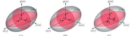
Fig.1.Eigen polarization directions in uniaxial crystals.(a)k along the x axis;(b)k along the z axis;(c)k deviated from principle axis.
2.3.Methods for SE cross-section measurement
The SE cross-section spectrum can be measured by two methods:laser operation method and Fuchtbauer–Ladenburg equation method.Laser operation method uses the laser performances such as slope efficiency,and threshold power to measure the gain.Thus,SE cross-section can be calculated via combining the overlap efficiency between mode beams and pump beams.[7,21]In these studies,the overlap efficiency is invariant because the propagating directions of laser is axial.However,the overlap efficiency is dependent on propagating directions in our study.The accurate knowledge of overlap efficiency of different propagating directions is hard to be solved,which makes it difficult to decouple SE cross-section from gain of the laser.Therefore,the Fuchtbauer–Ladenburg equation method is adopted in this paper.
The Fuchtbauer–Ladenburg equation is shown as below:

where λ refers to the wavelength of the fluorescent emission.n refers to the refractive index.τradis the fluorescence lifetime.I(λ)is the intensity of the fluorescent emission at λ.The SE cross-section spectrum is proportional to the normalized fluorescent emission spectrum.Hence,the SE cross-section spectrum for a certain propagating direction can be obtained by measuring the corresponding spectrum of the fluorescent emission.
3.Experimental setup
The experimental setup to measure the fluorescent emissions is illustrated in Fig.2.A laser diode(LD)from nLIGHT Photonics emitting at 808 nm is used as pump source to stimulate fluorescent emissions.The parameter of output coupling fiber is 400/0.22.Using two coupled lenses,the pump light with 10-W output power is focused into the crystal.A maximum pump-induced temperature increase of 10◦C is observed via a thermal camera.Three 12 mm×12 mm×2 mm Nd:YVO4specimens(0.3 at.%)are processed into a special shape.The c axis of the Nd:YVO4crystals is parallel to one of the 12-mm direction,marked as a dash line in Fig.2.Since the critical angle of total internal reflection in Nd:YVO4is only about 30◦,the crystals are cut into the wedge shape in order to make fluorescent emissions with large angles refract out the Nd:YVO4.As presented in Fig.3(a),the angle between the end face 2 and the wedge face 1,and the angle between the side face 2 and the wedge face 2 are both 30◦.The side face 1 is grinded in order to prevent parasitic oscillators inside the crystals.The Nd:YVO4crystals are mounted on copper heat sinks,which are cooled by circulating water.A polarizer is applied to discriminate the o light and the e light.A single mode fiber(SMF)is placed after the polarizer,and then connect to an optical spectrum analyzer(Agilent 86142B).By adjusting the directions of polarizer and SMF aligned to the corresponding fluorescence refracted from the crystal,the fluorescent emission spectra of different propagating directions in the Nd:YVO4crystals are measured for o light and e light.Since the NA of SMF is about 0.13(≈ 8◦),an aperture is inserted between the measured crystal and the polarizer as a field stop(Fig.3(b)),which restricts the acceptance angle to less than 5◦.Considering n ≈ 2 for Nd:YVO4,the fluorescence with an angular resolution of 2.5◦inside the crystals is received by SMF.
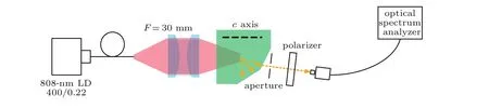
Fig.2.Experiment Setup of fluorescent emissions measurement system.

Fig.3.(a)diagram of the wedged Nd:YVO4crystals(The large faces of the crystals are unpolished.The end faces 1,2,the wedge faces 1,2,and the side face 2 are polished);(b)Diagram of the fluorescent signal received by SMF(polarizer is omitted to be convenient);(c)the exiting surfaces corresponding to fluorescent emissions of different propagating directions.
4.Data analyses and discussions
The fluorescent emission spectra are acquired at different θ values(0◦≤ θ ≤ 90◦)for three Nd:YVO4specimens respectively,where θ =0◦and θ =90◦correspond to the cases of wave vector k parallel and perpendicular to the c axis(as shown in Fig.1(b)and Fig.1(a),respectively).The fluorescent emissions of different directions are received after four different surfaces,as shown in Fig.3(c).The fluorescent emissions with θ =0◦–15◦,θ =15◦–45◦,θ =45◦–75◦,and θ =75◦–90◦are measured by the optical spectrum analyzer after the end face 2,the wedge face 1,the wedge face 2 and side face 2,respectively.The spectra for both the e light and the o light are acquired for wavelength range between 1050 nm–1110 nm for transition 4F3/2→4I11/2with a resolution of 0.06 nm.The power of emission peak is about several tens of pW to several hundreds of pW.Combined with other parameters in Eq.(1),the SE cross-section spectra of the o light and the e light are calculated:the fluorescence life time τradis98µs;[9]the refractive index n is considered as variable for different θ,according to refractive ellipsoid equation.
4.1.SE cross-section spectra of the e light
Figures 4(a)–4(j)illustrate the SE cross-section spectra of the e light of three Nd:YVO4specimens at θ =0◦,10◦,...,90◦accordingly.The spectra of θ =0◦and θ =90◦correspond to the σ -polarization and the π -polarization,respectively,which are consistent with results in Ref.[10].It can be observed that emission peaks of the σ-polarization locate around 1062 nm,1064 nm,1066 nm,1072 nm,1084 nm,and 1087 nm.Meanwhile,the positions of the emission peaks of π polarization(in Fig.4(j))are around 1064 nm,1073 nm,and 1085 nm,and the intensity of the emission around 1064 nm is much stronger than the others.
When θ increases from 0◦,the emission peaks around 1062 nm and 1066 nm start to decrease,while the intensity of the emission peak around 1064 nm grows gradually.The positions of the peaks around 1072 nm and 1084 nm also gradually transfer to 1073 nm and 1085 nm.For the intermediate state such as θ =40◦,50◦,the spectra around 1084 nm be-come more flat owing to the superposition of emission spectra around 1084 nm and 1085 nm.Thus,the shapes of the spectra of SE cross-section for the e light gradually approach to that in Fig.4(j).The relationship is coincident for all three Nd:YVO4specimens.These results reveals that the spectra of SE cross-section for the transition4F3/2→4I11/2are direction-dependent in Nd:YVO4.The SE cross-sections at 1064.4 nm vary from 5.5×10⁻¹⁹cm2,6.5×10−19cm2,and 5.9×10⁻¹⁹cm2to 13.4×10⁻¹⁹cm2,14.2×10−19cm2,and 16.0×10⁻¹⁹cm2when θ increases from 0◦to 90◦,for three specimens respectively,which are close to the values reported by Cornacchia[10]and Peterson.[11]
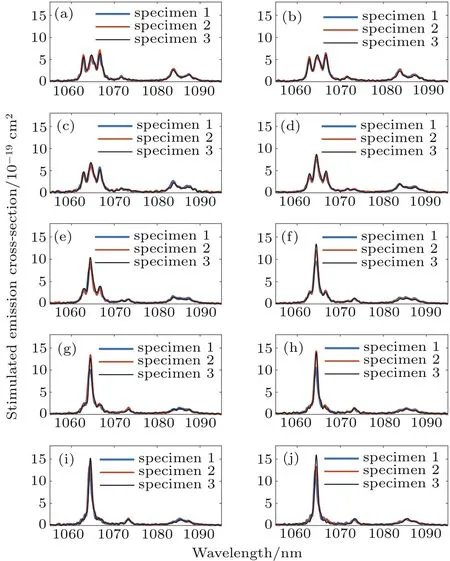
Fig.4.SE cross-section spectra of the e light at θ =0◦,10◦,...,90◦ (0◦–90◦corresponding to panels(a)–(j)).
4.2.SE cross-section spectra of the o light
The SE cross-section spectra of the o light of three specimens at θ =0◦–10◦,...,90◦are given in Figs.5(a)–5(j).It can be discovered that the intensity of emission around 1064 nm is generally close to that around 1062 nm and 1066 nm.Although the SE cross-section spectra of the o light should be consistent in any directions ideally,the measured spectra in our experiment fluctuate by to some extent.At several angles(such as θ =60◦in specimen 1),the intensity of emission around 1064 nm can exceed that of 1062 nm and 1066 nm.The minimum and maximum SE cross-section values measured from all angles of three specimens are 5.5×10⁻¹⁹cm2and 7.9×10⁻¹⁹cm2.Since the higher SE cross-section at 1064.4 nm of the o light is also observed in previous reports in different specimens,[10,11,22]we think the measured SE crosssection spectra and the SE cross-section value at 1064.4 nm of the o light fluctuate in a reasonable range.

Fig.5.SE cross-section spectra of the o light at θ =0◦,10◦,...,90◦(0◦–90◦ corresponding to panels(a)–(j)).
4.3.Anisotropic SE cross-section at 1064 nm
The characteristics of direction-dependent SE crosssection spectra in Nd:YVO4result in the anisotropic SE crosssection at a certain emission wavelength.Since the emission peak around 1064 nm is the most common wavelength in Nd:YVO4lasers,here we discuss the anisotropic SE crosssection at the wavelength of 1064.4 nm.The peak SE crosssection around 1064 nm under different propagating directions is given in Figs.6(a)and 6(b)for e light and o light,respectively.
In Fig.6(a),the SE cross-section grows slowly in θ =0◦–20◦,and then rise rapidly in θ =20◦–70◦,and finally the increase is saturated in θ =70◦–90◦.Due to the symmetry,it can be expected that the relationship of the SE cross-section against θ will be symmetrical to θ =90◦when θ =90◦–180◦.We assume that SE cross-section for an arbitrary propagating direction can be expressed as a superposition from two principle axial propagating directions with θ-dependent weights.Considering the physical origin that SE cross-section is proportional to normalized intensity of the fluorescence spectrum(Eq.(1)),the weight factor should be the square of cosine and sine function.

The measured SE cross-section of different θ in Fig.6(a)is fitted into the functional form of Eq.(2).The fitted σem,σfor three specimens are 5.7×10⁻¹⁹cm2,6.7×10−19cm2,and 6.1×10⁻¹⁹cm2,and the fitted σem,πfor three specimens are 12.9×10⁻¹⁹cm2,14.4×10−19cm2,and 16.0×10⁻¹⁹cm2respectively.Though the fitted parameters of three specimens have some deviations,the curve plotted in Fig.6(a) fits the measured points well,which proves the θ-dependent relationship of anisotropic SE cross-section mentioned above.It is verified that the peak SE cross-section(around 1064 nm)of e light at a certain propagating direction can be treated as a sum of plane projections of two of the SE cross-section of principle axial propagating directions.

Fig.6.the peak values of SE cross-section around 1064 nm versus different propagating directions(each θ with three measurements)(a)e light and(b)o light
Equation(2)provides a relationship of the anisotropic SE cross-section in Nd:YVO4,and characterizes the peak SE cross-section variation of the e light around 1064 nm caused by changing of propagating direction.It can not only describe the conventional eigen-porlarized SE cross-section but also characterize a complete propagating direction-dependent effect.Since the gain is proportional to SE cross-section,the laser with different propagating directions will get different gains.Therefore,the relationship is meaningful in the design of multi-folded light path laser systems.
The SE cross-section values of the o light in different directions have a fluctuation between 5.5×10⁻¹⁹cm2and 7.9×10⁻¹⁹cm2.The theoretical value should be a constant,however the fluctuations of SE cross-section might be caused by the nonuniformity of the crystal property induced by doped concentration and manufacturing process.The noise of the optical spectrum analyzer might also lead to the fluctuations of the measured SE cross-section values.
5.Conclusions
A new concept of the anisotropic SE cross-section is proposed and verified on Nd:YVO4crystals in this paper.With a special wedge-shaped Nd:YVO4crystal,the fluorescent emissions from different propagating directions are measured for both o light and e light. The SE cross-section for4F3/2→4I11/2transitions in Nd:YVO4is experimentally found to be propagating direction-dependent for the first time,to our best knowledge.An experimental relationship between the SE cross-section of e light and the propagating directions around 1064 nm is found:a superposition of the projection of SE cross-section of c-axis and a-axis propagations is capable of calculating the SE cross-section for a certain propagating direction.The relationship provides a quantitative reference for laser gain analyses and designs for oscillators and amplifiers with arbitrary laser propagating directions inside the Nd:YVO4.The proof of anisotropic SE cross-section in Nd:YVO4inspires us to explore the properties in other crystals.Other than Nd:YVO4,anisotropic crystals like GdVO4,YLF,and KGW with various doping ions are anticipated to have the anisotropic SE cross-section property,which is worth studying in future works.
[1]De´len X,Balembois F and Georges P 2012 J.Opt.Soc.USA B 29 2339
[2]Nie M,Liu Q,Ji E,Cao X,Fu X and Gong M 2016 IEEE J.Quantum Electron.52 1
[3]Taira T and Sato Y 2012 Opt.Mater.Express 2 1076
[4]Deloach L D,Payne S A,Chase L L and Smith L K 1993 IEEE J.Quantum Electron.29 1179
[5]Ramachandran S,Seshadri M,Ferencz Junior J A P,Ratnakaram Y C and Barbosa L C 2014 Fiber Lasers XI:Technology,Systems,and Applications
[6]Dong J,Bass M,Mao Y,Deng P and Gan F 2003 J.Opt.Soc.Am.B 20 1975
[7]Krishnan G,Bidin N,Ahmad M F S and Abdullah M 2015 Laser Phys.Lett.12
[8]Patel F D,Honea E C,Speth J and Payne S A 2001 IEEE J.Quantum Electron.37 135
[9]Balembois F,Georges P and De´len X 2011 J.Opt.Soc.USA B 28 972
[10]Cornacchia F,Turri G,Jenssen H P,Tonelli M and Bass M 2009 J.Opt.Soc.USA B 26 2084
[11]Peterson R,Jenssen H P and Cassanho A 2002 J.Opt.Soc.USA B 24 681
[12]Yoon S,Beecher S and Mackenzie J The European Conference on Lasers and Electro-Optics p.CEP 34
[13]Mao Y,Zhang H,Hao X,Yuan J,Xing J,Xin J and Jiang Y 2016 Opt.Express 24 11017
[14]Heese C,Oehler A E,Gallmann L and Keller U 2011 Appl.Phys.B 103 5
[15]Ma Z,Li D,Hu P,Shell A,Shi P,Haas C R,Wu N and Du K 2007 Opt.Lett.32 1262
[16]Manni J G 2005 Opt.Commun.252 117
[17]Liu Q,Nie M,Lu F and Gong M 2016 IEEE Photon.J.8 1
[18]Chang F L,Sung C L,Huang T L,Wu T W,Cho H H,Liang H C and Chen Y F 2017 Laser Phys.Lett.14 085803
[19]Liang H C,Wu T W,Tung J C,Tsou C H,Huang K F and Chen Y F 2013 Laser Phys.Lett.10 105804
[20]Li X,Yu X,Gao J,Peng J,Chen F,Yu J and Chen D 2008 Laser Phys.Lett.5 429
[21]Mukhopadhyay P K,George J,Sharma S K,Ranganathan K and Nathan T P S 2002 Opt.Laser Technol.34 357
[22]Sato Y and Taira T 2002 Jpn.J.Appl.Phys.41 5999
杂志排行

Chinese Physics B的其它文章
- Entangled multi-knot lattice model of anyon current∗
- Miniature quad-channel spin-exchange relaxation-free magnetometer for magnetoencephalography∗
- Observing the steady-state visual evoked potentials with a compact quad-channel spin exchange relaxation-free magnetometer∗
- Quantum interferometry via a coherent state mixed with a squeezed number state∗
- Cavity enhanced measurement of trap frequency in an optical dipole trap∗
- 7.6-W diode-pumped femtosecond Yb:KGW laser∗