扭力梁后桥剪切中心对悬架性能的影响
2018-11-14高大威陈海峰郑腾飞
高大威,陈海峰,李 翠,郑腾飞
(1.上海理工大学 机械工程学院, 上海 200093; 2.一汽大众汽车有限公司, 长春 130011)
1 Introduction
Torsion beam rear axles have been widely used in the A-class automobile market due to their simple structure and low manufacturing cost and its performance plays an important role in the performance of vehicle[1]. Despite the simple structure, however, the mechanism of the torsion beam rear axle is relatively complex because it features semi-independent suspension, and its shear center significantly affects the roll center and the operational stability of the entire vehicle.
The geometry of the hard points of a torsion beam rear suspension determine the positions, arrangements, and basic motion characteristics of the key parts in the system[2-4]. Its main hard points include the wheel center, the connection point between the longitudinal arm and vehicle body, the shock absorber and spring mounting point, the shear center of the beam, and the contact point between the wheel and the ground. Because the shock absorber and spring mounting point does not play a guiding role in the mechanism of the torsion beam rear suspension, the location of the beam shear center is critical on the development and design of torsion beam rear suspension.
Currently, the available research regarding the influence of the torsion beam shear center is relatively scarce to the K&C characteristics of a commercial vehicle[5]. The equation proposed in provided an approach for determining the location of the shear center for a torsion beam rear axle[3-4], but the meaning of some of the physical parameters involved was not provided. The geometric relationship was expressed in[6-7], but the coordinates of the hard points were not provided and no equation was developed. Neither of the studies presented here provided an approach to logically and quickly select the location of the shear center according to the height requirement of the roll center, nor was validation of the proposed approach conducted.
The present paper firstly establishes a torsion beam rear suspension model using virtual prototype software[8-9], and validates the model according to actual vehicle test data to ensure its accuracy. Then, the impact of variations in the shear center location on the roll center of the suspension is analyzed using a graphic method, and the results of the analysis are validated by simulation conducted using the virtual prototype software and experimental results. Finally, the impact of the shear center on the kinematics and compliance (K&C) characteristics of a torsion beam rear suspension were investigated through simulation experiments, and a logical selection method for the shear center of a torsion beam rear suspension is presented.
2 Establishment and validation of a torsion beam rear suspension model
2.1 Model establishment
To readily vary the location of the shear center, a torsion beam rear axle with a beam made from a stamped round pipe was selected for study. The opening direction of this type of rear axle can be varied by rotating the beam, with no impact on the welding of the beam and the longitudinal arm.
2.1.1Finiteelementmodelforthetorsionbeamrearaxle
The mathematical model of the torsion beam was introduced into HyperWorks for geometry cleanup and meshing. The resulting model consisted of 138 346 elements and 49 460 nodes. RB2 rigid connections were established at hard points. The corresponding material properties of the various elements of the torsion beam were assigned. The finite element model after meshing is shown in Fig.1.
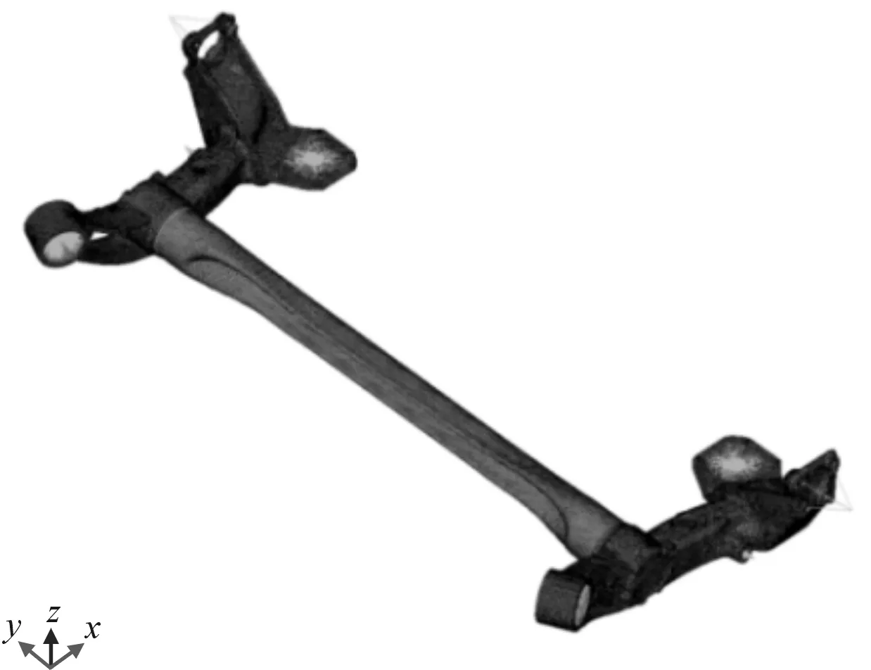
Fig.1 Finite element model of a torsion beam rear axle
2.1.2Generationofthemodalneutralfile
In the finite element model, eight hard points for the wheel centers, the connection points between the longitudinal arm and vehicle, the mounting points of shock absorbers, and the mounting points of springs, which are connected with other parts of the vehicle, were required to be treated as super elements. The parts deducted from the model by the static reduction method were denoted as super elements. In HyperWorks, the freedom degree[10]of the super element boundary is defined by a large number of input data given as either ASET or ASET1. This study adopted the super element boundary whose hard points were defined by ASET.
In defining the unit control card DTI_UNITS, the ton was used as the unit for mass, Newton was used as the unit for force, millimeter was used as the unit for length, and second was used as the unit for time. CMSMETH was used to define the GLOBLE_CASE_CONTROL card, which indicated that the modal response method was employed for obtaining the solution. ADAMSMNF was used to define the OUTPUT card, which selected for solution of the output modal neutral file, where optistruct was employed for generation of the modal neutral file. In the present study, modal neutral files were generated for all finite element models with eight azimuth angles.
The modal neutral file was introduced into MSC.Adams. Corresponding bushing, spring, shock absorber, and tire parameters were defined to establish the subsystems of the torsion beam rear suspension, as shown in Fig.2.
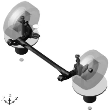
Fig.2 Simulation model of a torsion beam rear suspension
2.2 Experimental validation of the simulationmodel
The torsion beam rear suspension was loaded under parallel rotation, roll working, and longitudinal force conditions. The suspension model established in ADAMS was compared with actual vehicle testing data obtained in a K&C test bed, which not only validated the accuracy of the suspension experiment in ADAMS, but also provided preliminary insight into the K&C characteristics of torsion beam suspensions.
2.2.1 Parallel wheel travel of vehicle
This study selected two wheel alignment parameters for toe-in angle variation and camber angle variation to validate the accuracy of the ADAMS model. Fig. 3 and 4 show comparisons of actual vehicle test curves and ADAMS model curves.
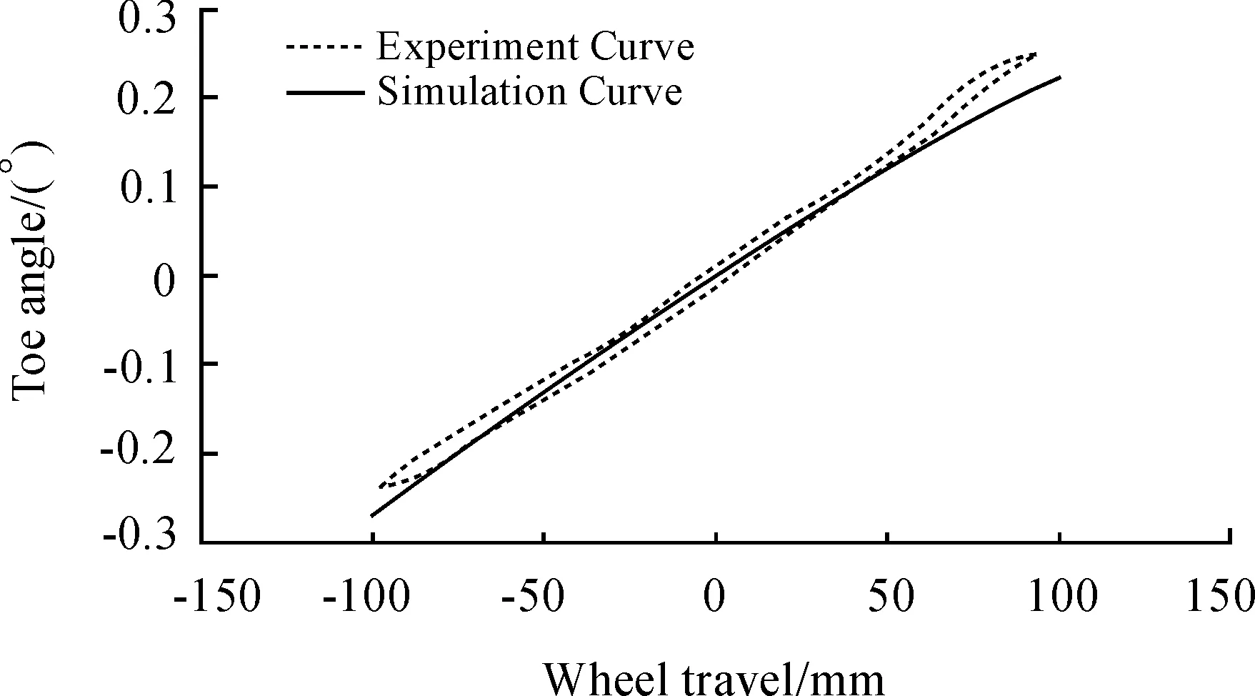
Fig.3 Toe-in angle variation for parallel wheel travel
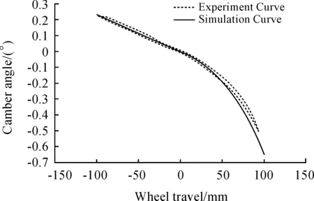
Fig.4 Camber angle variation for parallel wheel travel
2.2.2 Opposite wheel travel of vehicle
Variations of the toe-in angle and camber angle were used as wheel alignment parameters for validation, as shown in Fig.5 and 6.
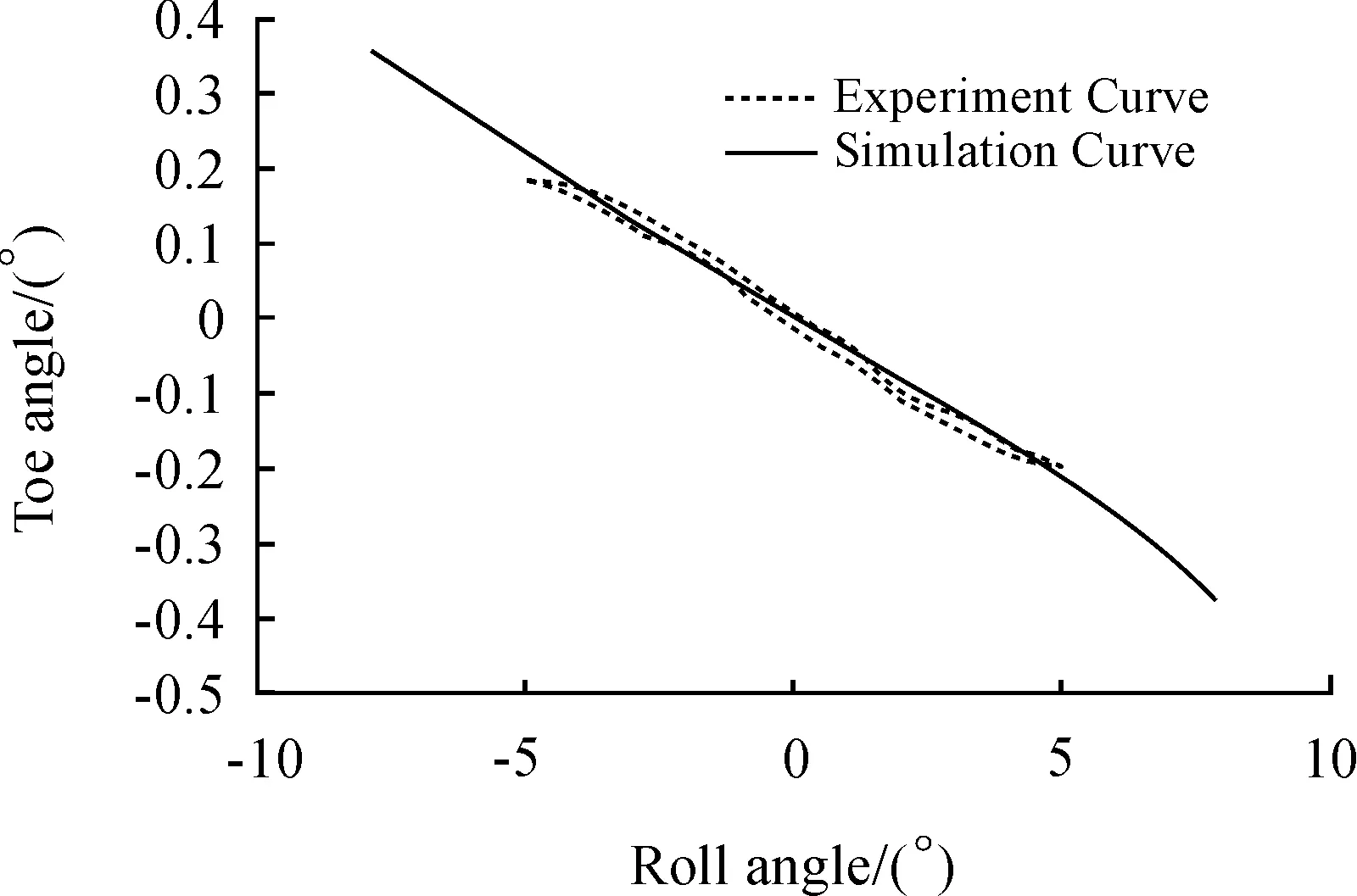
Fig.5 Toe-in angle variation for the vehicle roll condition
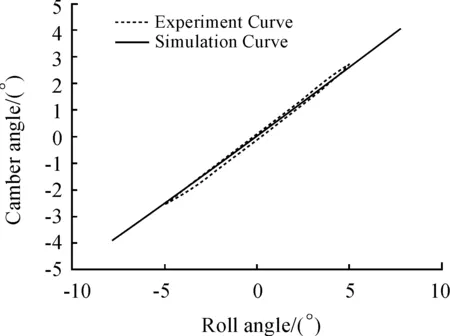
Fig.6 Camber angle variation for the vehicle roll condition
2.2.3 Longitudinal force condition
A longitudinal force of -1 000 N was loaded at the wheel center of the suspension for simulation testing of the rear suspension. Longitudinal force suspension stiffness and toe-in angle were used as the validation parameters, as shown in Fig.7 and 8.
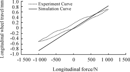
Fig.7 Longitudinal stiffness curve of the suspension
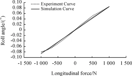
Fig.8 Toe-in angle variation under the longitudinal force condition
The results obtained from bench tests were basically consistent with those of the simulation testing. Due to the flexible body of the torsion beam model, the entire simulation system exhibited better accuracy.
3 Relationship between the shear center and suspension roll center and its validation
3.1 Relationship between the shear center and suspension roll center established by thegraphic method
The location of the roll center is determined by the guiding mechanism, and can be obtained by the graphic method[11]. The shear center of the torsion beam rear axle can be treated as a fixed point at the instantaneous roll, therefore, it can be regarded as an oblique arm type of suspension with a single hinge point. When the beam is moved forward toward the hinge point connecting to the vehicle body, it is treated as an independent single longitudinal arm suspension. When the beam is moved backward toward the wheel center, it is treated as a non-independent single longitudinal arm suspension[12]. Therefore, the torsion beam rear suspension features semi-indepen-dent characteristics. Despite its simple structure, its guiding mechanism is complicated.
The roll center of the torsion beam rear suspension can be determined from Fig.9. In Fig.9, when the torsion beam is with -90° azimuth angle,OlandOrare the connection points between the longitudinal arm and the vehicle body,Wis the ground contact point of the tire,WCis the wheel center,SCis the shear center of the beam,Pis the instantaneous center of the tires, andRoris the instantaneous roll center. Above all, the location ofPneeds to be determined. According to the approach employed, the intersection point of a line connectingOandSCand the wheel center axle line can be used to determine the lateral position ofP. From the back view, the intersection point of a line connectingOandSCand the lateral position ofPdetermines the height of, thus, the location ofPis completely determined. The roll centerRorcan therefore be determined by connectingPand the intersection point ofWand the vehicle center line.
We define the coordinates of the connection point on the left vehicle body side asO(Xo,Yo,Zo), left side wheel center point asWC(Xwc,Ywc,Zwc), shear center point asSC(Xsc,O,Zsc), left wheel contact point asW(Xwc,Ywc,Zw), wheel moving center point asP(Xp,Yp,Zp), and the roll center height ashRor. The definitions of the anglesα,β, andγare shown in Fig.1. According to the geometric relationships, the following equation can be determined.
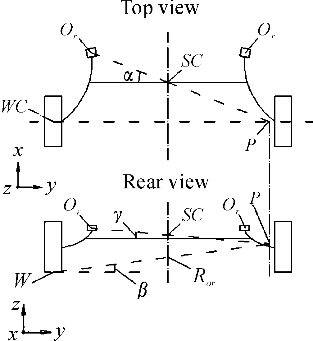
Fig.9 Guiding mode of the torsion beam opening setting on bottom
It is necessary to be explained that the position of shear center in Fig. 9 is the torsion beam opening setting on bottom. When the opening setting changes, the position of the shear center may change as well, but the following equation can also be used, because the geometric relationships will not change.
(1)
Then, the expression between the roll center and the various geometric hard points can be written as follows.
(2)
Here, when the positions of other hard points do not change, the relationship between the shear center and roll center can be observed. Accordingly, it can be determined that the impact of the shear center height on the roll center is linear, but, at the front and after locations, it is nonlinear. Moreover, the roll center height increases as the shear center height increases, and the shear center resides increasingly close to the wheel center as the height of the roll center increases.
3.2 Validation of graphic method by multi-body dynamics
3.2.1Selectionofbeamazimuth
Fig.10 shows the relationship between the beam middle section and the shear center. Point A above the cross-section in Fig. 10 represents the shear center, and PointBat the lower location is the geometric center. When the beam azimuth angle is varied, the shear center of the beam also varies with the rotation of the beam section as shown in Fig.10 (a) and (b).
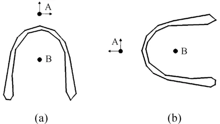
Fig.10 Beam middle cross section and shear center with -90°and 0°azimuth angle
To investigate the front, back, upper, and lower positions nearby the shear center to as great an extent as possible, we define the direction of the beam opening toward the vehicle head as 0°, and the beam conditions with eight azimuth angles of 0°,180°, ±45°, ±90°, and ±135° were validated.
3.2.2Comparisonofsimulationresultswiththoseofthegraphicmethod
Given the coordinates of various hard points:Ol(3 568, -545, 272),WC(4 001, -735, 280), andW(4 001, -735, -19), the shear center coordinates corresponding to various azimuth angles were: 0° (3 806, 0, 192), 45° (3 789, 0, 150), 90° (3 746, 0, 132), 135° (3 702, 0, 150), 180° (3 687, 0, 192), -135° (3 704, 0, 235), -90° (3 747,0,252), and -45° (3 789,0,234).
According to Equation (2), the graphic method can be used to determine the height of the roll center, and the corresponding results are presented in Table 1.
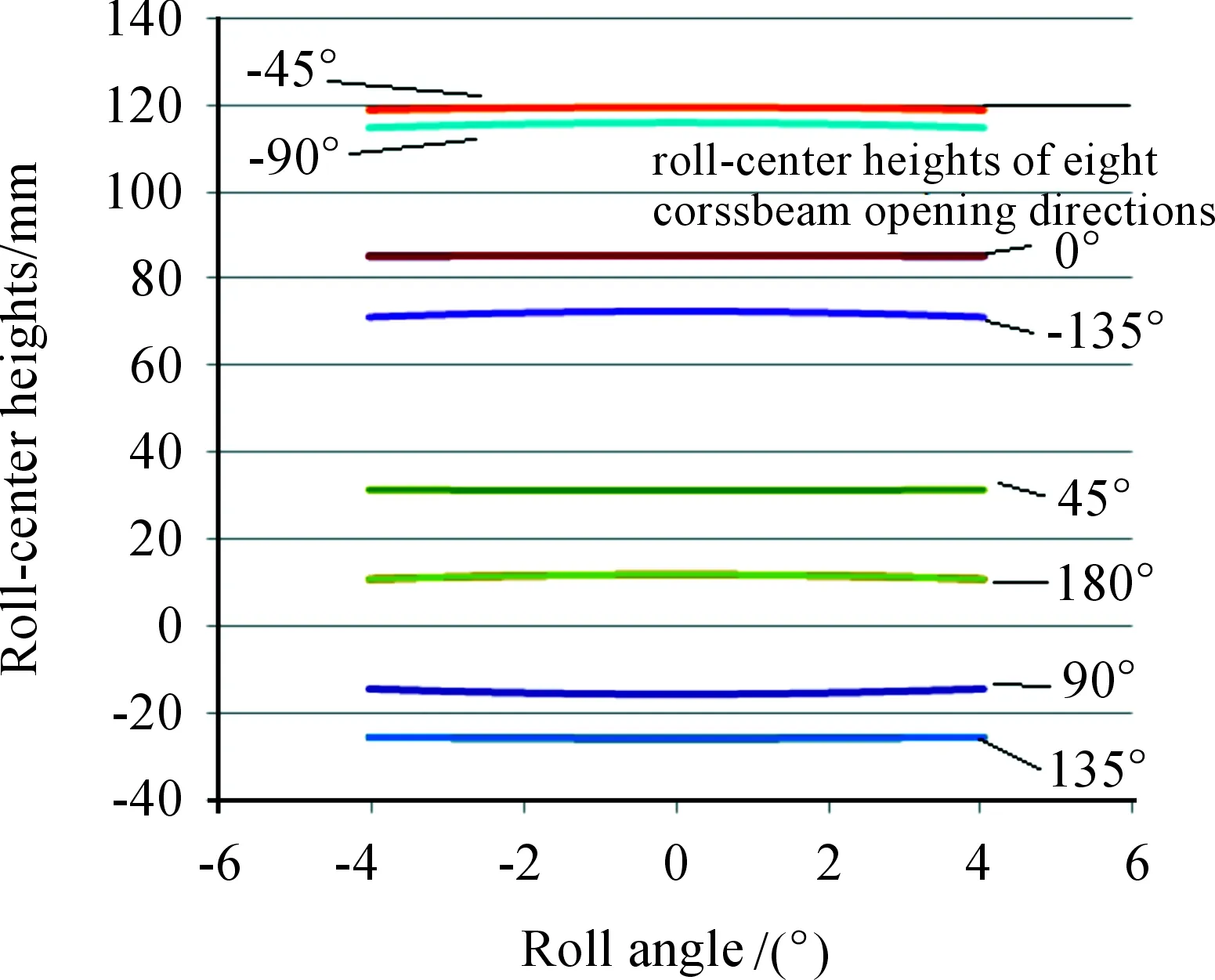
Fig.11 Simulation result of the roll center height

Azimuth angle/(°)Results from graphic method/mm Simulation results/mm Relative error/%090.48385.338-3.544530.36831.2260.0190-24.033-15.6875.74135-38.886-25.8738.95180-0.03111.8428.17-13566.12472.4654.36-90118.226115.912-2.28-45126.540119.500-4.84
After addinga±5° roll angle to the system, the simulated results for the roll center height are shown in Figure 11 and Table 1.The computational equation for the relative errors listed in Table 1 is
(hri-hki)/(hrmax-hrmin)×100%
(3)
Where:hrirepresents the result of No.isimulation,hkirepresents the result of No.igraphic method,hrmaxrepresents the maximum simulation height,hrminrepresents the minimum simulation height.
It can be observed from the results that the errors of the roll center height, as derived from the graphic and simulation methods, were less than 9%, which validates the accuracy of the equation derived from the graphic method. A possible main cause for the error is that the torsion beam in the graphic method is regarded as rigid, but is regarded as a flexible body in the simulation method[13-14]. In the graphic method, other main cause for error included ignorance of the azimuth angle and stiffness of the bushing.
As shown above, the roll center height reached its maximum value for an azimuth angle of -45°. The vehicle exhibited a small roll angle under the vehicle roll condition, which is beneficial to the lateral attachment of tires.
3.3 Validation of the graphic method by experiment
To better validate the accuracy of the derived equation, azimuth angles of 0° and -90° were respectively selected for actual vehicle validation.
3.3.1Rollcentercomputationbyexperimentaldata
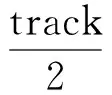
According to the definition of the roll center height[15], its computation is given by Equation (4) as follows:
(4)
where track is the wheel distance, and Δband Δsare the lateral and vertical displacements of the ground contact point of the tire, respectively.
Under the condition of opposite wheel travel, the experimental data of the lateral and vertical locations of the tire ground contact point can be used to plot a curve reflecting their relationship. Given the initial locations of -19 mm for the vertical location of the tire ground contact point, and -735 mm for the lateral initial location, and setting the initial location as the origin, the relationship curve between the lateral and vertical locations of the ground contact point can be obtained, as shown in Fig.12 and 13, when the left wheel travel was ±40 mm.
The slopekof the tangent lines is 8.547 3 and 6.682 4, respectively, which represents the lateral and vertical variation rates at the initial location of the tire ground contact point. From Equation (4), the roll center height can be determined by the reciprocal of k multiplying half the wheel distance. Given a wheel distance of 1 470 mm for Vehicle Type 1, the roll center height computed from the experimental data was 85.992 mm and 109.990 mm, respectively.
3.3.2Comparisonbetweenexperimentalresultsandthegraphicmethod
The roll center results computed from Equation (2) and the experimental results are provided in Table 2.It is observed that the errors fall within the range allowed by good engineering practice; therefore, the accuracy of the derived equation (Equation (2) is again validated, and can provide a basis for preliminary design of torsion beam rear axles.
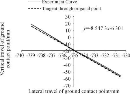
Fig.12 Experimental curve for the 0° beam azimuth angle ground contact point

Fig.13 Experimental curve for the -90° beam azimuth angle ground contact point
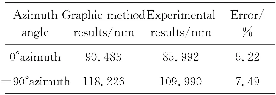
Azimuth angleGraphic method results/mm Experimental results/mm Error/%0°azimuth90.48385.9925.22-90°azimuth118.226109.9907.49
4 Impact of the shear center on suspension K&C characteristics
When the beam of the torsion beam is turned around, it is rotated about the shear center. When the suspension is subjected to the opposite wheel travel condition or the vehicle body roll condition, the torsion beam is turned around, and the shear center significantly impacts the K&C characteristics of the suspension.
4.1 Impact of the shear center on suspension K&C characteristics under the opposite wheel travel condition
Under the opposite wheel travel condition, the left and right wheels are loaded opposite to the ground vertical load, which is the most basic experimental condition in suspension K&C testing, and a ±100 mm vertical jump displacement was used as the loading condition. The variation of the wheel alignment parameters under the opposite wheel travel condition are shown in Fig.14 and 15.

Fig.14 Toe-in angle variation for various beam azimuth angles under opposite wheel travel
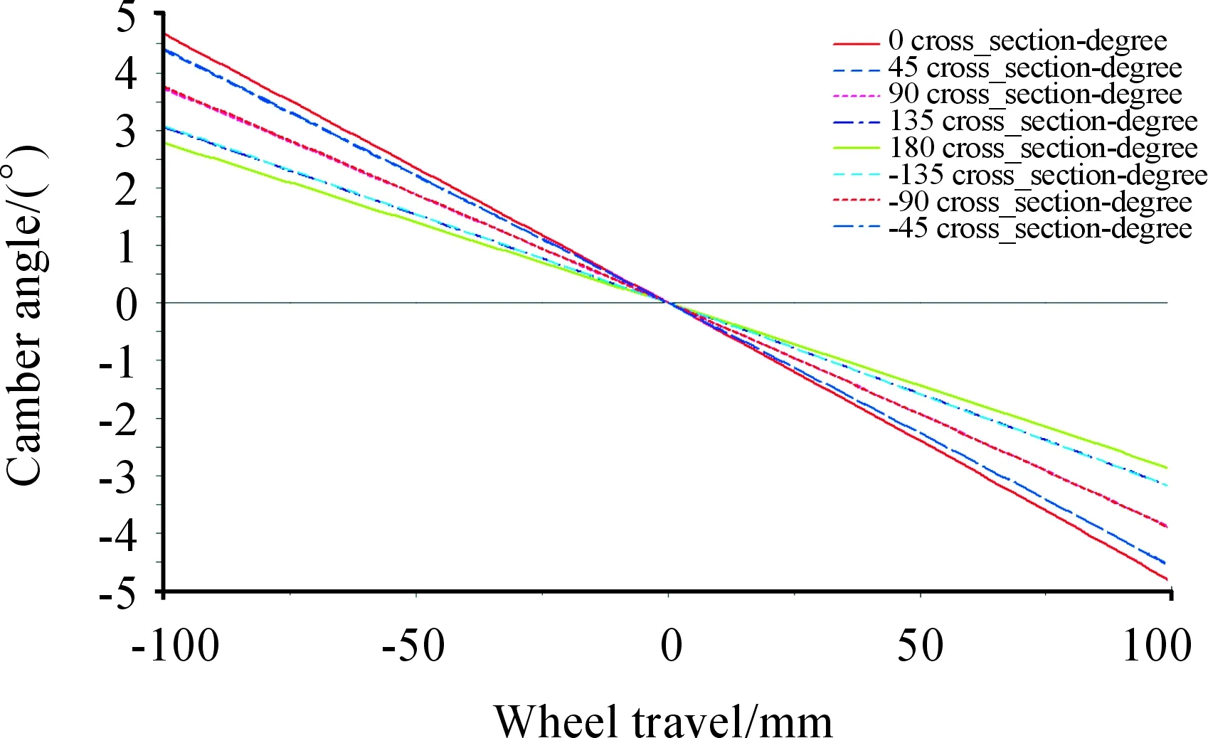
Fig.15 Camber angle variation for various beam azimuth angles under opposite wheel travel
Under the opposite wheel travel condition, the toe-in angle and the camber angle exhibit an evident change. The toe-in angle exhibited a minimum change at a beam azimuth angle of -90°, but the camber angle exhibited a minimum change at a beam azimuth angle of -180°. It is observed that the variation of the angle is correlated with the shear center height, and the variation of the camber angle is correlated to the front and back of the shear center.
4.2 Impact of the shear center on suspension K&C characteristics under the vehicle roll condition
Under the vehicle roll condition, the beam can also rotate. Therefore, the impact of the shear center on the vehicle roll condition is significant. Applying a ±10° heeling angle to the simulation assembly, and 7,350 N of vertical load to the rear suspension, the parameter variation curves of the torsion beam suspension for various beam azimuth angles are shown in Fig.16~19.
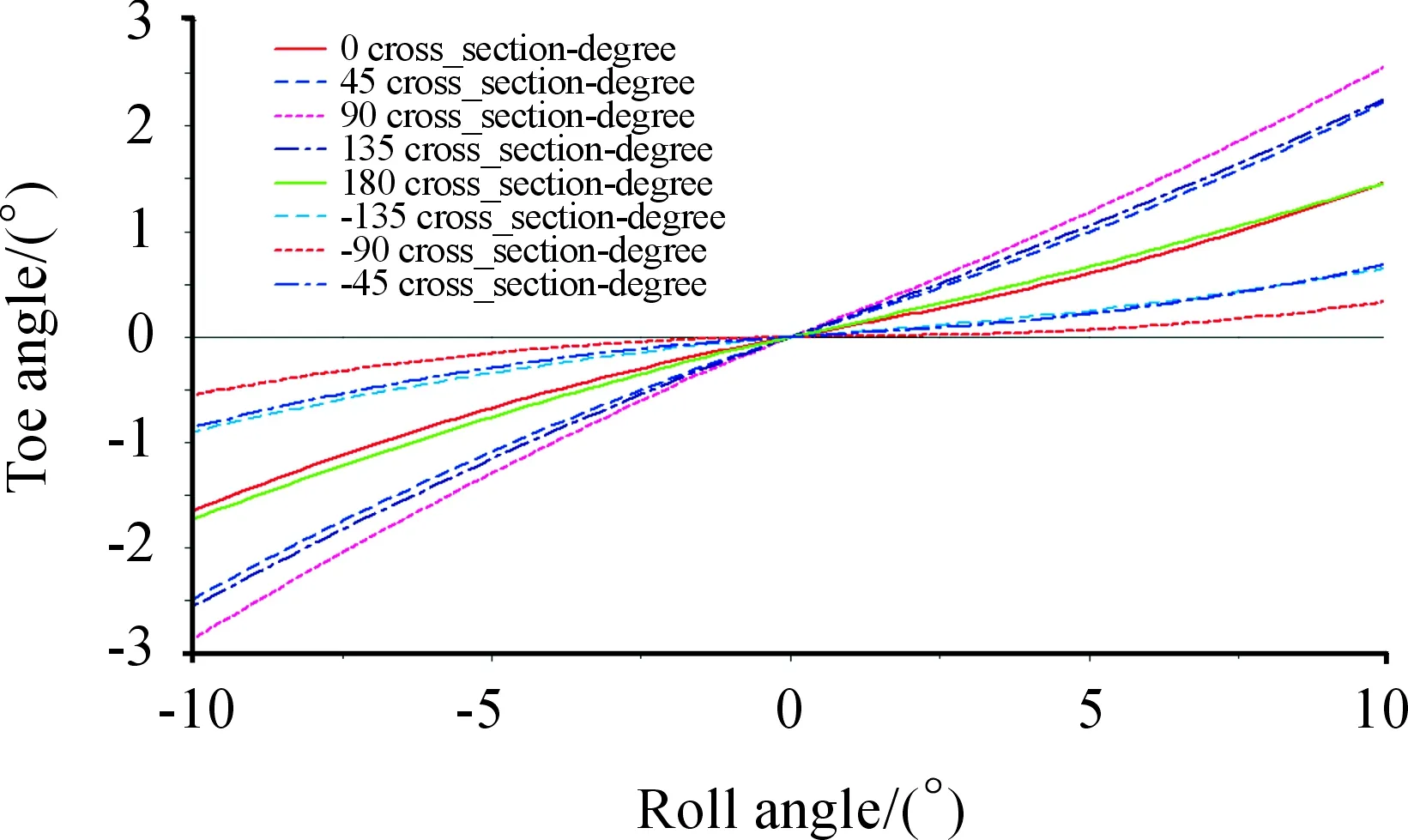
Fig.16 Toe-in angle variation for various beam azimuth angles under the vehicle roll condition

Fig.17 Camber angle variation for various beam azimuth angles under the vehicle roll condition
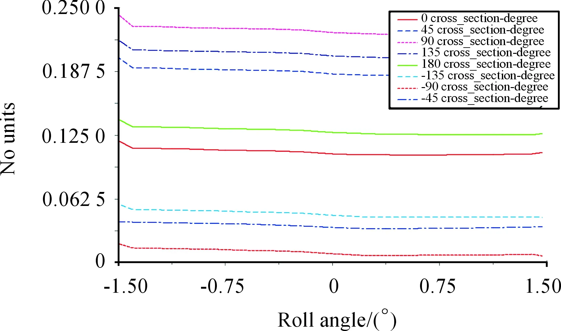
Fig.18 Roll steering ratio for various beam azimuth angles
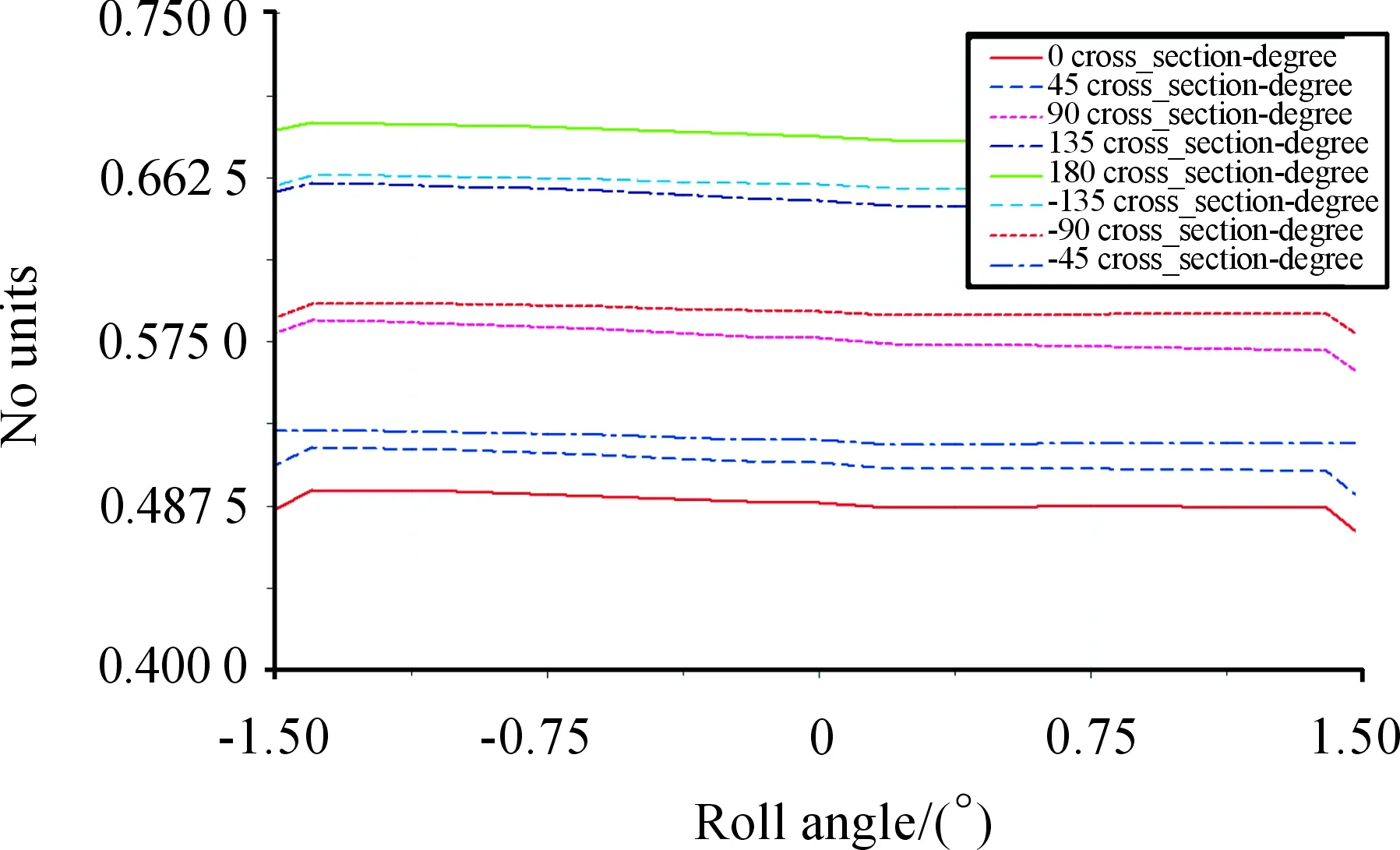
Fig.19 Camber steering ratio for various beam azimuth angles
It is observed from Fig. 16 that the toe-in angle varies significantly under a ±10° variation of the camber angle, where the roll camber angle was a minimum when the angle discrepancy was above 2.5° and the beam azimuth angle was -90°, and, when the beam azimuth angle was 90°, the camber angle attained a maximum value. It is evident that, under vehicle roll conditions, the shear center height impacted the magnitude of the toe-in angle of the wheel. The toe-in angle is observed to decrease as the shear center increases. This observation is beneficial to the operational stability and under-steer characteristics of a vehicle.
It is observed from Figure 17 that a variation of the shear center led to about a 2° fluctuation in the camber angle of the wheel to ground, and the variation of camber angle was obviously related to the front and back locations of the shear center. The variation of camber angle was a minimum for a beam azimuth angle of 0°.
It is noted that a smaller camber angle is conducive to the stability of a vehicle while turning under roll conditions; however, under the condition of non-roll opposite wheel travel, because the camber angle of the wheel to ground is identical to the camber angle relative to the vehicle body, the camber angle due to the wheel jump exhibited a higher change, and diminished comfort and stability. Therefore, this situation should be avoided during vehicle design.
4.3 Summary of shear center location selection
The selection of the torsion beam shear center can be summarized as below.
1) The front and back locations of the shear center for the torsion beam had a significant impact on the camber angle under vehicle roll and opposite wheel travel conditions. When the shear center location was at the back, the rear suspension exhibited a smaller roll steering ratio and roll camber ratio. However, the camber angle attained a maximum value under the condition of opposite wheel travel, which is not conducive to rear passenger comfort and operational stability on bumpy roads. Therefore, the shear center of the front and rear positions should compromise, and, generally, the selection of the shear center should control the roll camber ratio at about 50%.
2) The upper and lower positions of the shear center had a significant impact on the toe-in angle of the rear suspension. When the shear center was located at a higher position, both the vehicle roll and opposite wheel travel conditions exhibited a smaller variation of the toe-in angle. When the rear suspension was subjected to a lateral force, the rear wheel sideslip angle was along the direction of the centrifugal force[16]; therefore, when the suspension structure itself was subjected again to a lateral force, there was a tendency of over-steering. Locating the shear center at a higher position helped to alleviate this trend, and, accordingly, increased the operational stability of the vehicle. Therefore, after determining the location of the shear center, the shear center should be arranged as high as possible in the allowable range of the torsion beam structure topology.
3) It was better to use the graphic method introduced in this paper to compute the roll center location of the suspension. The roll center should not be too high, nor should it be lower than the roll center of the front suspension. The roll center of the back suspension was generally controlled within 50~200 mm.
5 Summary
1) This paper established a rigid-flexible coupling simulation model of a torsion beam rear suspension using the simulation software ADAMS, and validated the model through actual vehicle experimental data to ensure the accuracy of the simulation.
2) This paper established the geometric relationship between the shear center of the torsion beam, hard points, and the roll center of the suspension by a graphic method, and validated this geometric relationship using a simulation model and experimental data.
3) This paper investigated the impact of the torsion beam shear center on the K&C characteristics of the suspension, and summarized an appropriate approach for selecting the shear center(As shown in subsection 3.3).
Declaration of conflicting interests
The author(s) declared no potential conflicts of interest with respect to the research, authorship, and/or publication of this article.
Funding
The author(s) disclosed receipt of the following financial support for the research, authorship, and/or publication of this article: This project is supported by National Natural Science Foundation of China (Grant No. 51305269) and Shanghai Automotive Industry Science and Technology Development Foundation of China (Grant No. 1744)