Predicting the sinkage of a moving tracked mining vehicle using a new rheological formulation for soft deep-sea sediment*
2018-05-07XUFeng许锋RAOQiuhua饶秋华MAWenbo马雯波
XU Feng (许锋) , RAO Qiuhua (饶秋华) , , MA Wenbo (马雯波)
1 School of Civil Engineering, Central South University, Changsha 410075, China
2 College of Civil Engineering and Mechanics, XiangTan University, Xiangtan 411105, China
1 INTRODUCTION
It is well known that there are rich mineral resources below the seabed in the deep sea. Recently, the exploitation of deep-sea resources has been attracting increasing attention from researchers and engineers all over the world (Lin et al., 1991; Rao et al., 2009).Currently, there are a few systems for mining deepsea minerals (known as nodules), e.g., the continuous chain-bucket method, a method involving compressed air and a hydraulic lift, and the shuttle down-the-hole lift method. All of these mining systems consist of five main parts: a mining ship, a flexible hose, a buff er, a rigid pipe, and a tracked mining vehicle. In particular, the movement characteristics of the mining vehicle on the seabed play an important role in deepsea mining operations (Lv et al., 2004).
Soft deep-sea sediments have higher water content,greater void ratio, and lower shear strength than do land soils, and are more rheological in nature (Chen et al., 2013; Ma et al., 2014a). Hence, tracked mining vehicles that operate on deep-sea beds can easily slip or even sink into the seabed, causing the mining operation to fail (Gigler and Ward, 1993; Caccia et al., 2000; Letherwood and Gunter, 2001; Dai, 2010).With regard to tracked mining vehicles, there have been various studies of how they interact with land soil. Bekker theory and Reece theory have been used to investigate the effect of the vertical bearing force ofsuch soil on vehicle sinkage, and the effect of the soil shear strength on the vehicle traction force (Schiff man,1961; Bekker, 1969; Pan, 1986; Shen and Yu, 1989;Wong, 2001; Li and Li, 2010). However, those studies either failed to consider the rheological properties of land soil or only considered such properties in one direction (compression or shear). For soft deep-sea sediment, there have been even fewer studies of the influence of its rheological properties on the performance of tracked mining vehicles, let alone its combined compression-shear rheological properties.

Table 1 Physical and mechanical properties of the soft deep-sea sediment

Table 2 Physical and mechanical properties of sediment simulants and deep-sea sediment
In the present study, we prepare an artificial material to simulate the properties of soft deep-sea sediment from a poly-metallic nodule mining area in the Pacific Ocean. We conduct compressive creep tests under different compressive stresses and shear creep tests under different compressive and shear stresses. These tests are intended to simulate the shear and compressive stresses that a mining vehicle exerts simultaneously on the soft sediment because of its weight and movement. The creep tests are used to obtain compressive and shear rheological parameters to establish a compression-sinkage model and a combined compression-shear rheological constitutive model. The combined compression-shear rheological sinkage of the tracked mining vehicle is calculated for different speeds by using the RecurDyn software with a self-programmed combined compression-shear rheological constitutive model for comparison with shear rheological sinkage and ordinary sinkage (i.e.,without considering the rheological properties). The developed RecurDyn software can be used to study the performance and structural optimization of the moving tracked mining vehicle.

Fig.1 Compressive creep test
2 COMPRESSIVE AND SHEAR CREEP TESTS
2.1 Preparation of the deep-sea sediment simulant
In this study, we focus on the soft deep-sea sediment from a C-C poly-metallic nodule mining area in the Pacific Ocean (1 000 m deep). Its physical and mechanical properties are given in Table 1 in relation to particle size, liquid plastic limit, specific surface,compressive modulus, cohesion, and internal friction angle (Ma et al., 2014b).
Because the supply of this sediment was limited,we had to find a sediment simulant for the various experimental studies that we wished to conduct.Usually, a sediment simulant is a mixture of bentonites and water (Schulte et al., 2003; Ma et al., 2014a, b).Therefore, we prepared four types of sediment simulant (namely S1–S4) by mixing four forms of bentonite with different percentages of water, as listed in Table 2 (Ma et al., 2014a); the water content is defined as the ratio of water content to solids content.In Table 2, we see that the S3 sediment simulant is the closest to the deep-sea sediment in relation to their physical and mechanical parameters, and therefore is the best substitute material.
2.2 Testing procedure
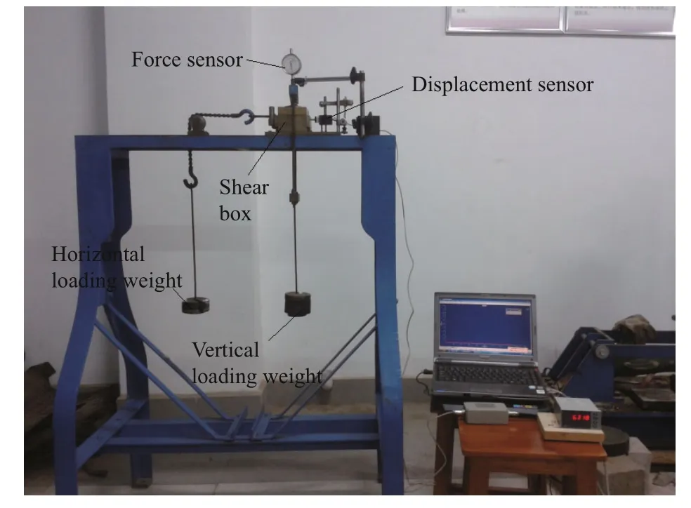
Fig.2 Shear creep test

Fig.3 Compressive creep curves for different σ
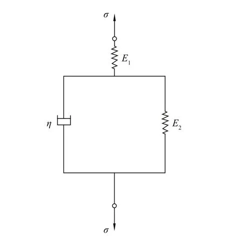
Fig.4 Kelvin-Hooke rheological model (K-H)
The compressive-creep test equipment shown in Fig.1 was used to obtain compressive-creep curves for each sediment simulant over a range of compressive stressσ=5–30 kPa in 5-kPa steps. In the sediment container, weights on the bearing plate applied a specific constant compressive stressσto the sediment simulant. The associated vertical displacementzwas recorded automatically every second (with high precision) by a displacement sensor on the bearing plate until the displacement had stabilized (Ma et al.,2016).
Because the compressive stress at the interface between the track shoe and the deep-sea sediment has an appreciable effect on the shear displacement (i.e.,movement) of the tracked mining vehicle, we conducted shear-creep tests under constant compressive stress to determine the appropriate shear rheological model of the sediment simulant. Figure 2 shows a shear-creep apparatus that was designed in house, in which a specific compressive stress (again,σ=5–30 kPa in 5-kPa steps) was applied by a vertical loading weight and a specific shear stressτ(τ=1–6 kPa in 1-kPa steps) was applied by a horizontal loading weight. Under specific constant values ofσandτ(36 groups in total), the shear displacementswas recorded automatically every second (with high precision) by an NS-WY02 displacement sensor until the displacement had stabilized (Ma et al., 2014a).
3 COMPRESSIVE AND SHEAR RHEOLOGICAL CONSTITUTIVE EQUATIONS
3.1 Compressive rheological constitutive equation
Figure 3 illustrates the compressive creep curves of the deep-sea sediment simulantunder different constant values of compressive stressσ. The Kelvin-Hooke rheological model (Fig.4), containing two springs and one dashpot, is used to fit these curves(z-t) by transferring theσ-ε(compressive-stresscompressive-strain) equation (Eq.1) to theσ-z(compressive-stress-sinkage) equation given in Eq.2:
whereE1andE2are the compressive elastic moduli of the sediment simulant andηis its viscosity;
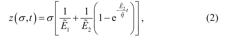
Figure 5 shows the test data (solid points) inz-t-σspace and the curved surface of Eq.2 fitted using the Table Curve-3D curve and surface fitting software.Table 3 lists the fitted compressive creep parameters,where the coefficient of determinationR2is 0.985.

Fig.5 Fitted curved surface in z- t- σ space with test data

Fig.6 Shear creep curves for σ=5 kPa (as an example)
Table 3 Compressive creep parameters
3.2 Combined compression-shear rheological constitutive equation
Figure 6 shows typical shear-creep curves for the sediment simulantfor different values ofτforσ=5 kPa. The Burgers rheological model (Fig.7),containing two springs and two dashpots, is used to fit these curves (s-t), where theτ-γ(shear-stress-shearstrain) equation (Eq.3) is transferred to theτ-s(shearstress-shear-displacement) equation (Eq.4) (Ma et al.,2014a):

whereK1andK2are the shear moduli of the sediment simulant, andη1andη2are its viscosities;
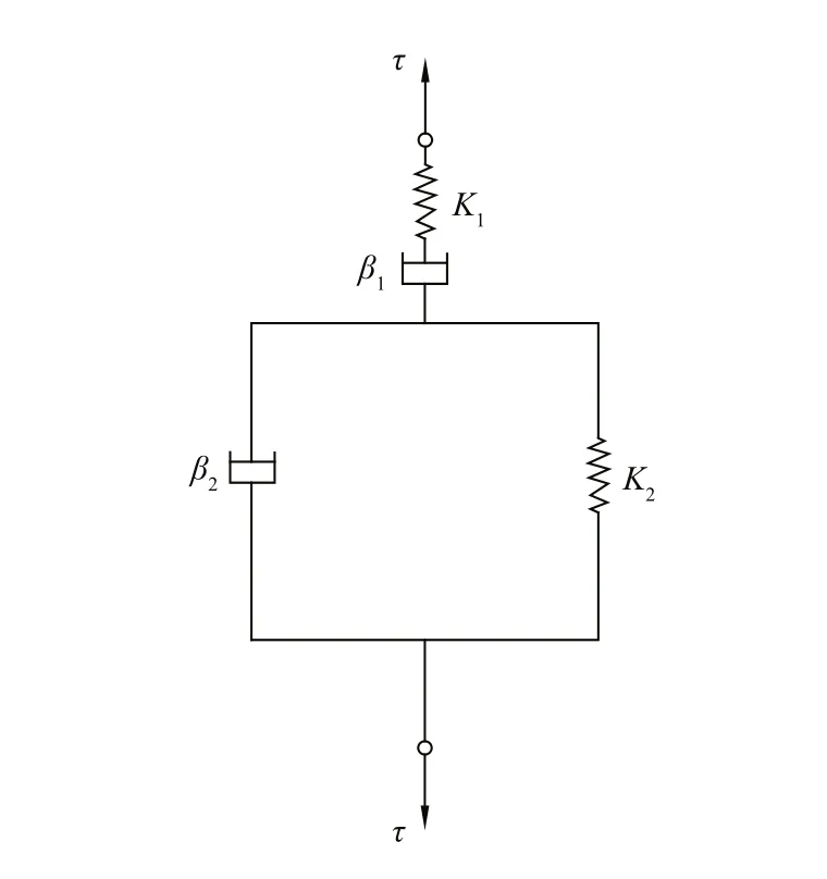
Fig.7 Burgers rheological model
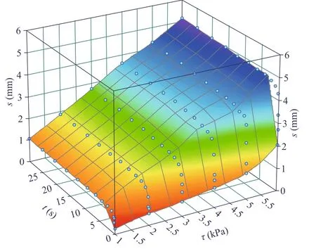
Fig.8 Fitted curved surface with test data in s- t- τ space( σ= 5 kPa)
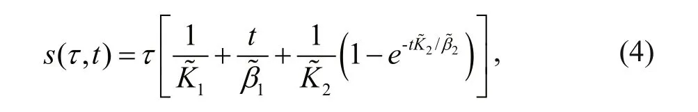
whereandare shear elastic parameters proportional to the shear moduliK1andK2,respectively, andandare shear viscous parameters that are proportional to the viscositiesη1andη2, respectively. Equations 3 and 4 clearly have the same form except for, andinstead ofK1,K2,β1, andβ2.
Figure 8 shows the test data (solid points) ins-t-τspace and the curved surface of Eq.4 fitted using TableCurve-3D for the instance ofσ=5 kPa. Table 4 lists all of the fitted shear-creep parameters under differentσ, in which the coefficients of determinationR2are close to unity. Clearly, these shear creep parameters are all dependent onσ. The shear rheological equation, Eq.4, can be rewritten as Eq.5,where, andare functionsof fitted with data in Table 4. Obviously, the shear displacementsis influenced by the constant compressive stressσapplied in the shear-creep tests.

Table 4 Fitted shear-creep parameters

Table 5 Geometrical parameters of the crawler
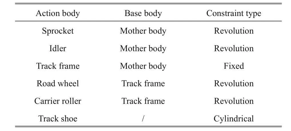
Table 6 Constraint type of each component

4 SINKAGE SIMULATION OF THE MOVING TRACKED MINING VEHICLE
4.1 Self-programming of compression-shear rheological constitutive model

Fig.9 Three-dimensional model of moving tracked mining vehicle
We used the multi-body dynamics simulation software RecurDyn (Recursive Dynamic) to calculate the sinkage of the moving tracked mining vehicle based on the combined compression-shear rheological properties of the soft deep-sea sediment. Because the RecurDyn software incorporates only the independent compression-sinkage model proposed by Bekker(1969) and the shear stress-displacement model proposed by Janosi and Hanamoto (1961), the combined compression-shear rheological constitutive model had to be self-programmed into the RecurDyn software, as well as the direct-shear rheological constitutive model and ordinary constitutive model(without consideration of rheological properties) for comparison.
Microsoft Visual Studio 2005 was used to program and compile the compression-shear rheological constitutive model written in the FORTRAN language, namely CSRCM.for in short. File CSRCM.for must be put in the same current directory as SOLVER.LIB and SYSCAL.F files of RecurDyn, and DFORDLL.LIB, DCONSOL.LIB, and DFPORT.LIB files of FORTRAN, in order to generate the executive file CSRCM.DLL as a called user subroutine in the RecurDyn software.
4.2 Calculation model
As shown in Fig.9, a simplified tracked mining vehicle was used, consisting of two steel crawlers and a steel mass block on the top. This vehicle moves on a deep-sea sediment simulant with the combined compression-shear rheological properties introduced by CSRCM. for program. Each crawler has 32 track shoes, three road wheels, two carrier idlers, one sprocket, one idler, and one track frame. Its geometric parameters are listed in Table 5, and Table 6 gives constraint type of each component.

Fig.10 Combined compression-shear rheological sinkage at different vehicle speeds
Because the actual speed of a moving tracked mining vehicle on the seabed is usually in the range of 0.5–1.0 m/s (Chen et al., 2004), the speed range (v) of 0.5–2.0 m/s was adopted for the simulation calculations in this study, as well as the motionless case (v=0) for comparison. The centroid rheological sinkage of the tracked mining vehicle was calculated by the RecurDyn software with the self-programmed CSRCM.DLL for the rheological properties of the deep-sea sediment simulant. The subsystem toolkit in RecurDyn was used to create and assemble the various components (i.e., track shoe, sprocket, idler,road wheel, carrier roller, track frame, and mass block). The detail procedures are 1) to set the modeling environment parameters (including units, material types, acceleration due to gravity, and orientation); 2)to create the track shoes by inputting their geometrical data and grouser profile; 3) to create the sprocket and idlers by adjusting their geometrical data and tooth profiles; 4) to create the road wheels and carrier rollers by modifying their hub and flange radii; 5) to assemble the components after choosing the track frame and mass block (i.e., the simplified tracked mining vehicle); 6) to create an analysis job and set the analysis type and simulation time; 7) to create the deep seabed model under the tracked mining vehicle model and adjust their relative position.
5 RESULT AND ANALYSES
Figure 10 shows the combined compression-shear rheological sinkagezof the tracked mining vehicle at different vehicle speedsv. These curves can be divided into two stages: the instantaneous displacement occurring during the initial loading period (t=0–0.2 s),and the creep sinkage (t=0.2–10 s). Clearly, the sinkage decreases and tends to become more stable as the vehicle moves faster. This is because creep varies with time, and hence there is less time for the deepsea sediment simulant to creep when the tracked mining vehicle moves faster, whereby the creep sinkage becomes smaller. Those results are consistent with the findings of Bekker (1969), and so we conclude that the RecurDyn software is reliable.

Fig.11 Direct-shear rheological sinkage at different vehicle speeds
Figure 11 shows the direct-shear rheological sinkagezof the tracked mining vehicle at different vehicle speeds (v), in whichσis equal to 5 kPa in compression-shear rheological constitutive model.Compared with Fig.10, it can be seen that the directshear rheological sinkage is smaller than the combined compression-shear rheological sinkage at the same speed. Because the compressive stress (σ) at the interface between the track shoe and the deep-sea sediment simulant changes as the tracked mining vehicle moves, it has a considerable effect on the direct-shear rheological properties of the deep-sea sediment simulant. Therefore, the combined compression-shear rheological model rather than the direct-shear rheological model must be taken into account in predicting the sinkage of the tracked mining vehicle.
Figure 12 shows the ordinary sinkage (z) at different speeds (v) without consideration of the rheological properties of the deep-sea sediment simulant. It is can be seen that with the related constitutive equation and the parameters from the literature (Han, 2014) that are input directly into RecurDyn, the sinkage curves become steady after 1 s and reach the same value(roughly 20 mm in depth in Fig.12) after 4 s, neither of which are influenced by the vehicle speed.
By comparing the sinkage curves in Fig.12 with those in Figs.10 and 11 at the same vehicle speed, we conclude that the sinkage without consideration of rheological properties is much smaller than that with consideration of rheological properties, and that the combined compression-shear rheological sinkage is the largest among those sinkages at the same vehicle speed. Noticeably, the rheological properties of the deep-sea sediment simulant have a considerable effect on the sinkage of the tracked mining vehicle.
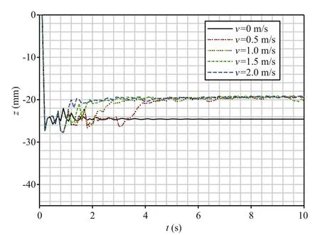
Fig.12 Ordinary sinkage at different vehicle speeds (without consideration of rheological properties)
6 CONCLUSION
1) The best deep-sea sediment simulant was obtained by mixing bentonite with a certain percentage of water in order to have the closest physical and mechanical properties to those of the soft deep-sea sediment, including wet density, water content,cohesion, and internal friction.
2) The combined compression-shear rheological constitutive model must be taken into account when calculating the sinkage of the tracked mining vehicle.This is because the shear rheological parameters of the sediment simulant are influenced greatly by the compressive stress (which changes as the tracked mining vehicle moves).
3) The combined compression-shear rheological sinkage of the tracked mining vehicle at different speeds was calculated by the RecurDyn software with a self-programmed compression-shear rheological constitutive model. This sinkage decreased with vehicle speed.
4) The ordinary sinkage (i.e., without consideration of the rheological properties) was much smaller than that with consideration of the combined compressionshear and direct-shear rheological properties. The combined compression-shear rheological sinkage was the largest.
5) The RecurDyn software with a self-programmed compression-shear rheological constitutive model can be used to study the movement performance and structural optimization of a tracked mining vehicle.
7 ACKNOWLEDGEMENT
The authors would like to thank the National Natural Science Foundation of China for financial support, and the State Key Laboratory of Exploitation and Utilization of Deep Sea Mineral Resources (Joint Lab of Central South University and Changsha Research Institute of Mining and Metallurgy) for technical support.
Bekker M G. 1969. Introduction to Terrain-vehicle Systems.University of Michigan Press, Michigan, USA.
Caccia M, Indiveri G, Veruggio G. 2000. Modeling and identification of open frame variable configuration unmanned underwater vehicles.IEEEJournalofOceanic Engineering,25(2): 227-240.
Chen F, Gui W H, Wang S P, Shen D Y, Han X Y. 2004.Modeling and simulation of a deep seabed tracked vehicle.
Robot,26(6): 510-514. (in Chinese with English abstract)
Chen G Q, Yi L, Chen S L, Huang H J, Liu Y X, Xu Y H, Cao J R. 2013. Partitioning of grain-size components of estuarine sediments and implications for sediment transport in southwestern Laizhou bay, China.Chinese JournalofOceanologyandLimnology,31(4): 895-906.
Dai Y. 2010. The Modeling Research and Simulation Analysis on the Single-rigid-body of Tracked Miner Moving on the Seafloor. Central South University, Changsha, China. (in Chinese)
Gigler J K, Ward S M. 1993. A simulation model for the prediction of the ground pressure distribution under tracked vehicles.JournalofTerramechanics,30(6): 461-469.
Han Q J. 2014. Slip and Path Tracking Control of the Deep Sea Tracked Miner. Central South University, Changsha,China. (in Chinese with English abstract)
Janosi Z, Hanamoto B. 1961. The analytical determination of drawbar pull as a function of slip for tracked vehicles in deformable soils.In: Proceedings of the ISTVS 1st International Conference on Mechanics of Soil-Vehicle System. Edizioni Minerva Tecnica, Turin, Italy. p.707-736.
Letherwood M D, Gunter D D. 2001. Ground vehicle modeling and simulation of military vehicles using high performance computing.ParallelComputing,27(1-2): 109-140.
Li L, Li S L. 2010. Simulation and mechanical characteristics of terra-mechanics of the surface soil on deep-sea bed.EngineeringMechanics,27(11): 213-220. (in Chinese with English abstract)
Lin Z H, Li X L, Cronan D S, Hodkinson R A. 1991.Compositional variations in manganese nodules collected from the North Penrhyn Basin.ChineseJournalof OceanologyandLimnology,9(4): 347-357.
Lv D, He J S, Liu S J. 2004. Current study status of exploiting technology to deep-ocean resource.Mining&Processing Equipment, (9): 6-9. (in Chinese)
Ma W B, Rao Q H, Li P, Guo S C, Feng K. 2014a. Shear creep parameters of simulative soil for deep-sea sediment.JournalofCentralSouthUniversity,21(12): 4 682-4 689.
Ma W B, Rao Q H, Wu H Y, Guo S C, Li P. 2014b. Macroscopic properties and micro structure analyses of deep-sea sediment.RockandSoilMechanics,35(6): 1 641-1 646.(in Chinese with English abstract)
Ma W B, Rao Q H, Xu F, Feng K. 2016. Impact compressive creep characteristics of simulative soil for deep-sea sediment.MarineGeoresources&Geotechnology,34(4):356-364.
Pan J Z. 1986. The general rheological model of paddy soils in south china.JournalofTerramechanics,23(2): 59-68.
Rao Q H, Wang Z, Liu S J, Fang M. 2009. Interaction of fluidsolid coupled flexible hose and mining machine in deepocean mining system.In: Proceedings of the Eighth ISOPE Ocean Mining Symposium. International Society of Off shore and Polar Engineers, Chennai, India. p.263-269.
Schiff man R L. 1961. Analysis of the displacements of the ground surface due to a moving vehicle.In: Proceedings of the First International Conference on Mechanics of Soil Vehicle Systems. Turin, Italy. p.45-62.
Schulte E, Handschuh R, Schwarz W. 2003. Transferability of soil mechanical parameters to traction potential calculation of a tracked vehicle.In: Proceedings of the 5th ISOPE Ocean Mining Symposium. International Society of Off shore and Polar Engineers, Tsukuba, Japan. p.123-131.
Shen J, Yu Q. 1989. Pressure-sinkage-time equation for wet soil.TransactionsoftheChineseSocietyforAgricultural Machinery,20(4): 15-19. (in Chinese with English abstract)
Wong J Y. 2001. Theory of Ground Vehicle. 3rded. John Wiley& Sons, New York, USA.
杂志排行

Journal of Oceanology and Limnology的其它文章
- An aftereffect of global warming on tropical Pacific decadal variability*
- Analysis of monthly variability of thermocline in the South China Sea*
- A numerical study of the South China Sea Warm Current during winter monsoon relaxation*
- Chemical characterization of fractions of dissolved humic substances from a marginal sea—a case from the Southern Yellow Sea*
- The morphological and molecular detection for the presence of toxic Cylindrospermopsis (Nostocales, Cyanobacteria) in Beijing city, China*
- Solid sand particle addition can enhance the production of resting cysts in dinoflagellates*