用于高性能硫化镉敏化太阳能电池对电极的硫化铜/还原氧化石墨烯纳米复合材料的合成
2018-03-15AmrHesseinAhmedAbdElMoneim
Amr Hessein, Ahmed Abd El-Moneim
(1. Department of Materials Science and Engineering, Egypt-Japan University of Science and Technology, New Borg El Arab City, Alexandria21934, Egypt; 2. Department of Mathematical and Physical Engineering, Faculty of Engineering (Shoubra), Benha University, Cairo, Egypt)
1 Introduction
Quantum dots-sensitized solar cell (QDSSC) is a promising candidate as the next generation solar cell owing to the ease of fabrication and the low production cost[1]. The photoanode of QDSSCs simply comprises a mesoporous layer from a wide bandgap semiconductor (usually TiO2) that is sensitized with a narrow bandgap QDs such as CdS, CdSe and PbS[2-4]. Upon excitation and due to the bandgaps offset, the photogenerated electrons from the conduction band of QDs are injected into the TiO2conduction band, and then passing to the external circuit through the front electrode. The initial state of the QDs is restored by means of electron donation from a polysulfide (S2-/Sx2-) electrolyte. The electrons are collected from the external circuit by the counter electrode (CE) and used to regenerate the oxidized compounds in the polysulfide electrolyte. Owing to the unique optoelectronic properties of QDs such as bandgap tunability, high extinction coefficient, and multiple exciton generation capabilities, 44% theoretical power conversion efficiency (PCE) has been predicted for QDSSCs[5]. Nonetheless, the experimental PCE of QDSSCs is still far below than the theoretical value due to the non-satisfactory electrodes designs.
In QDSSCs, the CE plays a pivotal role in collecting the electrons from the external circuit and catalyzing the reduction of the oxidized species in the (S2-/Sx2-) electrolyte[6-8]. A high electrochemical activity, long-term chemical stability and durability besides low-cost and ease of fabrication are the prerequisites for a high performance CE. Due to the high electrocatalytic activity of Cu2S for Sx2-reduction, a thin-film from Cu2S formed by exposing brass sheet to a polysulfide electrolyte is commonly used in CE of QDSSCs. However, the QDSSC devices fabricated based on the Cu2S/brass CE exhibited an inferior instrumental stability[9]. This is because the continual reaction between the brass substrate and the polysulfide electrolyte resulted in peeling off the Cu2S layer from the brass substrate, leading to the contamination of the electrolyte and the photoanode. Alternatively, various metal sulfides (CuxS, PbS, NiS, CoS, etc) thin-films prepared on FTO substrate with different coating methods such as successive ionic layer adsorption and reaction (SILAR)[10], chemical bath deposition (CBD)[11], hydrothermal method[12]and electrophoretic deposition[13]have been investigated as CEs for QDSSCs.Besides the low charge carrier mobility and chemical stability issue, the aforementioned approaches do not meet the requirements for the large-scale production[14].Thereby, the fabrication of a highly-efficient and durable CE is considered to be one of major challenges encountered by the researchers to realize practical applications of QDSSCs.
Recently, graphene with its excellent electronic, conductive and mechanical properties has been considered as a promising alternative material to fabricate efficient electrodes in many electrochemical applications[15-18]. Graphene produced from the oxidation and reduction of graphite is preferable to fabricate graphene-based electrode for electrochemical and energy-related applications. The reduced graphene oxide (RGO) usually suffered from the aggregation and restacking problems, which resulted in poor electrical conductivity and catalytic activity of the graphene electrodes[19]. However, the excellent chemical stability and high specific surface area of RGO represent a perfect framework to immobilize inorganic nanoparticles (NPs) for further improvements in the electrocatalytic activity and stability of the fabricated electrodes[20].
In this work, the photovoltaic performance and stability of CdS QDSSC are totally improved by developing a highly efficient CE from CuxS NPs and RGO sheets. The CuxS/RGO nanocomposites were prepared by a facile one-step hydrothermal process for the in-situ synthesis of CuxS NPs and reduction of graphene oxide. The effect of initial concentration of graphene oxide on the morphological, structural and electrochemical properties of the as-prepared CuxS/RGO nanocomposites had been studied by means of FE-SEM, XRD, Raman spectroscopy, and electrochemical measurements. The CEs based on the CuxS/RGO composite were fabricated by the simple drop casting method of catalyst ink directly on the FTO substrate and processed at low temperature under ambient atmosphere. Compared to the conventional Cu2S/brass CE, CdS QDSSC based on the optimized CuxS/RGO CE showed a 50% enhancement in the PCE and an excellent performance stability under the normal operation condition.
2 Experimental
2.1 Preparation of CuxS/RGO nanocomposite
Herein, a nanocomposite from CuxS nanocrystals decorated on RGO sheets was prepared by a facile and scalable one-pot hydrothermal method. In the beginning, a clear GO aqueous solution was obtained by exfoliating graphite oxide in distilled water under mild sonication for 2 h. 20 mL of copper acetate [Cu(OAc)2] (1mmol) solution with a water and ethylene glycol volume ratio of 1∶1 was added dropwise to 100 mL of GO solution under vigorous stirring. The Cu(OAc)2-GO mixture was further stirred at room temperature for 1 h. After that, 5 mmol of thiourea dispersed in 10 mL of distilled water was added to the Cu(OAc)2-GO mixture and stirred for another hour. The mixture was then transferred to a 150 mL Teflon lined stainless-steel autoclave and hydrothermally treated at 200 ℃ for 24 h. The excess amount of thiourea was used to ensure the complete reaction of all the Cu2+ions with the S2-ions, and also as a reducing agent for the GO. After the autoclave was cooled down to room temperature, a black precipitate of CuxS/RGO nanocomposite was collected and washed several times with distilled water and ethanol using a centrifuge and dried in an electric oven at 60 ℃ overnight. The initial amount of GO in the mixture was changed to 50 mg (CuxS/RGO50), 100 mg (CuxS/RGO100), and 150 mg (CuxS/RGO150).
2.2 Fabrication of CuxS/RGO CEs
The CuxS/RGO CEs for QDSSC applications were prepared by the simple drop casting method directly on an FTO substrate. Firstly, 45 mg of as-prepared CuxS/RGO nanocomposites were separately mixed with 5 mg PVDF as a binder in 1 mL NMP by ultrasonication for about 1 h. The CuxS/RGO CEs were obtained by drop casting 10 μL of the prepared coating inks on a pre-cleaned FTO substrate of an exposed area of 1 cm2, followed by drying at 110 ℃. For comparison, RGO, and Cu2S/brass CEs were fabricated and tested in parallel with the CuxS/RGO CE composite. The RGO was prepared by the chemical reduction of GO with hydrazine hydrate, and the CE was fabricated by a similar method to the CuxS/RGO CEs. The Cu2S/brass CE was fabricated by vulcanizing a brass sheet with a polysulfide electrolyte[21].
2.3 Fabrication of QDSSC devices
QDSSC photoanodes were prepared on a pre-cleaned FTO with a surface resistivity of 7 Ω/sq (Asahi Glass). A mesoporous layer of TiO2P25 of 10.5±0.2 μm thickness was coated by the doctor blade technique over a TiO2dense blocking layer and sintered at 500 ℃ for 1 h[22]. The coating paste was prepared by mixing TiO2P25 and ethyl cellulose as a binder in terpineol[23]. The surfaces of the photoanodes were then further treated with 100 mM TiCl4aqueous solution at 70 ℃ for 30 min.
All photoanodes were sensitized with CdS QDs using the successive ionic layer adsorption and reaction (SILAR) method. Briefly, the photoanode was immersed for 1 min in 0.2 mol/L Cd(NO3)2·4H2O in methanol as a cation source (Cd2+) to be adsorbed on the TiO2layer. The photoanode was then rinsed with methanol to remove the excess Cd2+cations and dried under N2atmosphere. Then, the photoanode was immersed in a 0.2 mol/L Na2S (methanol:water 1∶1) solution as the anion source (S2-) for 1 min, which was rinsed with methanol and dried under N2atmosphere. This four-step procedure was considered as one SILAR cycle. All the photoanodes were sensitized with 10 CdS SILAR cycles and also passivated with a ZnS layer obtained with four SILAR cycles using 0.1 mol/L cation and anion precursor concentrations.
The QDSSC devices were fabricated by assembling the photoanodes and CEs into sandwich-type solar cells with Parafilm as a spacer between the two electrodes. A regenerative polysulfide electrolyte (S2-/Sx2-) composed of 1 mol/L Na2S, 1 mol/L S, and 0.1 mol/L KCl in distilled water was used to fill the space between the two electrodes. The active area of solar cells was fixed at 0.16 cm2by clamping a metal shadow mask to the solar cell surface using binder clips.
2.5 Measurements and characterization
The morphology of the samples was characterized by field-emission scanning electron microscopy (FE-SEM) using a JEOL JEM-6500F scanning electron microscope. X-ray powder diffraction (XRD) was used to investigate the crystallinity of the samples using a diffractometer (Rigaku RINT 2100 PC) operating with a Cu target as theKαX-ray radiation source. Raman scattering spectra were measured with a Raman microscope (RAMAN touch) using a laser wavelength of 532 nm. UV-visible absorption spectra were recorded on a Hitachi U- 4000 spectrometer equipped with a diffuse reflectance unit. Photovoltaic measurements were performed using a solar simulator (San-Ei Electric XES-40S1) at AM 1.5 with 1 sun illumination intensity (100 mW/cm2), and current density-voltage (J-V) data were recorded using a source meter unit (Keithley SMU 2400). The AM 1.5 condition for the solar simulator was confirmed using a standard silicon solar cell (BS-500BK). Incident photon-to-current conversion efficiency (IPCE) measurement was performed by a DC measurement method with an IPCE system (Bunkoukeiki SM-250). Electrochemical measurements were carried out on an electrochemical workstation (CH Instruments 660E). The sample used for the electrochemical measurements was a symmetrical dummy cell fabricated from two identical CEs separated with a spacer and the polysulfide electrolyte filling the space.
3 Results and discussion
3.1 Structure and morphology measurements
The surface morphologies of CuxS/RGO nanocomposites were investigated by means of FE-SEM at low and high magnifications as shown in Fig. 1. As seen, the 2D structure of the RGO sheets is decorated with CuxS nanoparticles(NPs), where their sizes and distribution on RGO sheets are clearly controlled with the initial amount of GO in the solution. In the case of CuxS/RGO 50 sample as shown in Fig. 1(a, a1), the RGO sheets are densely covered with CuxS NPs of different sizes in the range of 100 - 150 nm, besides some large CuxS particles in the micro scale. The formation of large and agglomerated particles can be attributed to the insufficient amount of RGO sheets that were available for CuxS deposition during the preparation.
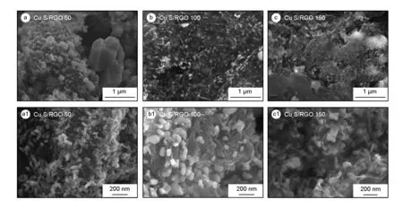
Fig. 1 FE-SEM micrographs of as-prepared CuxS/RGO nanocomposites.
For CuxS/RGO 100 sample as shown in Fig. 1 (b, b1), a high and uniform coverage, without aggregation, of well anchored CuxS NPs on the surface of transparent and thin 2D-RGO sheets can be obviously seen.The CuxS NPs show lateral dimensions in the range of 50 - 100 nm. On the other hand, the surface morphology of CuxS/RGO 150 sample as shown in Fig. 1(c, c1), show a uniform distribution of embedded CuxS NPs, the lateral dimension is in the range of 50 - 100 nm, among thick RGO sheets. The thicker RGO sheets obtained, which may negatively affect the electrochemical activity of the nanocomposite, is directly related to the excess starting concentration of GO.
Fig. 2(a) shows the XRD diffraction patterns of CuxS/RGO nanocomposites and GO starting precursor. As seen, the diffraction peak related to the GO was completely disappeared in the patterns of CuxS/RGO nanocomposites, confirming that the hydrothermal method can be effectively used to remove the oxygen functional groups from the GO and restoring thesp2-hybridization of graphene sheets. It is worth to mention that no obvious peaks of RGO can be seen in the diffraction patterns of CuxS/RGO composites. This can be attributed to the uniform coverage of RGO sheets with crystalline CuxS NPs, which minimize the restacking of RGO sheets, hence causing the disappearance of the RGO diffraction peaks[24].
On the other hand, all the diffraction peaks of the presented patterns for CuxS/RGO nanocomposites are well indexed to the hexagonal covellite phase of cupric sulfide CuS (JCPDS Card No. 00-006-0464) and rhombohedral Digenite Cu1.8S phase (JCPDS Card No. 00-047-17480)[21], where their fraction and degree of crystallinity is determined by the starting concentration of GO in solution precursors. The addition of copper source cations foremost to the GO solution makes copper ions to distribute firstly on the GO sheets network, acting as reaction sites ready to interact with the sulfide ions added lately. The variation in the GO concentration will result in a change in the number of copper ions located in every reaction site on the GO network. This resulted in different stoichiometry of the final obtained phase of CuxS in the nanocomposite.
For CuxS/RGO 50 composite, the peaks assigned for Cu1.8S phase show a higher intensity than those assigned for CuS phase, indicating that Cu1.8S is the predominant phase. Comparable peak intensities from both CuS and Cu1.8S phases were obtained in CuxS/RGO 150 nanocomposite. While, all the peaks related to the CuS phase show a higher intensities than those corresponding to Cu1.8S phase in the CuxS/RGO 100, indicating that CuS is the predominant phase in the assembled nanoparticles on RGO sheets. Finally, CuxS/RGO 100 nanocomposite show a higher degree of crystallinity compared with other nanocomposites. Hence, the CuxS/RGO 100 nanocomposite with a higher covellite CuS content is expected to show a higher electrochemical activity towards polysulfide electrolyte than the other two samples[25].
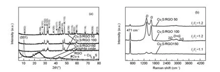
Fig. 2 (a) XRD, and (b) Raman spectra of as-prepared CuxS/RGO nanocomposites.
The Raman spectra of as-prepared CuxS/RGO nanocomposites are shown in Fig. 2(b). In addition to theDandGbands of graphene, a sharp band that located at 471 cm-1is present in the Raman spectra of all samples. This peak was assigned to the stretching mode of S-S atoms in covellite CuS nanoparticles[26, 27]. The presence of CuS Raman band proved the successful attachment of CuxS nanoparticles on the graphene layers and formation of CuxS/RGO nanocomposite[28]. Also, the higher S-S band intensity with respect to D and G peaks of graphene in the CuxS/RGO 50 confirms the higher content of CuxS particles in the final product, while the weaker S-S peak in CuxS/RGO 150 reveals the higher RGO content. The moderate S-S band intensity in the CuxS/RGO 100 indicates the integration between CuS nanocrystals and RGO in the nanocomposite. It is also worth noting that the (ID/IG) ratio in CuxS/RGO composite is in the range between 1.1 and 1.2, which is generally lower than 1.3 for the chemically reduced RGO. This indicates the effectiveness of hydrothermal method in producing RGO with a fewer numbers of defects.
3.2 Electrochemical properties
The electrochemical activities of all fabricated CuxS/RGO and Cu2S/brass CEs were evaluated by means of cyclic voltammetry (CV), electrochemical impedance spectroscopy (EIS), and Tafel polarization measurements on symmetric cells from two identical CEs as presented in Fig. 3. Generally, all the CuxS/RGO CEs possess a better electrochemical performance than the bare RGO CE, which points out to the role of CuxS particles in improving the activity of RGO towards (S2-/Sx2-) electrolyte. The CV curves in Fig. 3(a) reveal the superior electrochemical activity exhibited by CuxS/RGO 100 CE between all the fabricated CEs. A very high reduction current density (Jred) equals to 75.93 mA/cm2was obtained by CuxS/RGO 100 CE, much higher than 37.87 mA/cm2obtained from the state of the art Cu2S/brass CE. This superior activity of CuxS/RGO 100 CE is a direct result of the preferred and fast reduction of oxidized Sx2-ions from the larger number of active sites afforded by the uniform distribution of CuxS nanocrystals on conductive RGO sheets as previously presented in FE-SEM micrographs.
Fig. 3(b) shows EIS Nyquist plots of the CE symmetrical cells measured in the frequency range from 0.1 Hz to 100 kHz at a zero bias voltage and AC ramp amplitude of 20 mV. Two typical semicircles are observed for all symmetrical cells in the higher and lower frequency regions. The series resistance (Rs) of the CE determined from the onset of the high frequency semicircle (~100 kHz) comprises the bulk resistance of the CE material and the sheet resistance of the supporting substrate. The high frequency semicircle is attributed to the charge-transfer resistance (RCT1) and the constant phase element (CPE1) at the solid-solid interface, while the low frequency semicircle is consistent with theRCT2and CPE2 at the electrolyte-CE interface. The EIS plots were fitted by the Zsimpwin software to the equivalent circuit shown in the inset of the low-impedance-range plots for the CuxS/RGO 100 and Cu2S/brass CEs shown in Fig. 3(c), and the fitted EIS parameters are summarized in Table 1.

Fig. 3 (a) CV, (b) EIS, (c) low range EIS and (d) Tafel plots of all CuxS/RGO and Cu2S/brass CEs. The inset of (c) shows the equivalent circuit used to fit the EIS data.
Among all the fabricated CEs, the Cu2S/brass CE shows the smallestRsbecause of the high electrical conductivity of the brass substrate. On the other hand, among all newly developed CEs, the CuxS/RGO 100 CE shows the lowest impedance, which indicates its higher electroactivity. Accordingly, the CuxS/RGO 100 CE yieldsRsof 7.35 Ω, slightly higher than the FTO sheet resistance, which reveals the high conductivity of the CuxS/RGO 100 nanocomposite. This result also proves the effective reduction for the GO by the hydrothermal method at this initial concentration. Moreover, the novel CuxS/RGO 100 CE exhibits the lowestRCT1(1.50 Ω) among all the CEs, which refers to the strong binding between the CuxS/RGO and FTO substrate. The low electron transfer resistance at CuxS/RGO-FTO interface is favorable for fast electrons collection from the external circuit and rapid injection of the collected electrons into the conduction band of the CuxS nanocrystals. The CuxS/RGO CE also shows a smallerRCT2(5.54 Ω) than the Cu2S/brass CE (17.29 Ω), indicating its superior electrocatalytic activity for reduction of Sx2-ions and effective holes scavenging from the polysulfide electrolyte[9, 29].
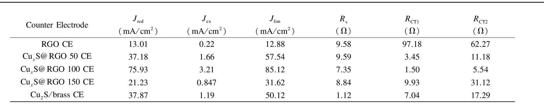
Table 1 Calculated electrochemical parameters for all CuxS/RGO and Cu2S/brass CEs.
The electrochemical activities of the fabricated CEs were also evaluated by performing Tafel polarization measurements on the symmetric cells at a scan rate 10 mV/s. The recorded Tafel plots in Fig. 3(d) of all the fabricated CEs also confirm the superior catalytic activity of CuxS/RGO 100 CE to the Cu2S/brass CE. The exchange current density (Jex) estimated from the intercept of the extrapolated linear regions in at zero overpotential Tafel plot was used to evaluate the CE activity. The novel CuxS/RGO 100 CE shows a superiorJexof 3.2 mA/cm2, higher than 1.19 mA/cm2of the Cu2S/brass CE, and much higher than 0.22 mA/cm2for the RGO CEs. These results are in close consistent with the results of the charge transfer resistances previously estimated from EIS measurements asJexis directly related toRCTaccording to the relation:
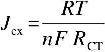
(1)
whereRis the universal gas constant,Tis the temperature,nis the number of electrons, andFis Faraday’s constant. Additionally, the highest limiting current density (Jlim) of 85.12 mA/cm2was obtained from the CuxS/RGO 100 CE, indicating the very low diffusion impedance of electrolyte that renders a better electrolyte infiltration into CuxS/RGO 100 CE than the other CEs.
In summary, the combination of RGO and CuxS in CuxS/RGO nanocomposites through hydrothermal reduction is found to accelerate charge transfer for polysulfide reduction, which was more significant than reducing the series resistance of the fabricated CE. Furthermore, changing the initial concentration of the GO was responsible for the variation in the particle size and the CuxS stoichiometric ratio in the final obtained nanocomposites. In consistency with the expectation from the morphological examination of as-prepared samples, the CuxS/RGO 100 CE shows the best electrochemical activity among the other CEs. This is caused by the well-defined dense and uniform distributed CuxS nanocrystals onto and between the surfaces of the conductive RGO sheets and a higher content of CuS NPs than Cu1.8S. Consequently, the significant low values ofRCT1andRCT2along with the highJlimandJexvalues obtained for CuxS/RGO 100 CE greatly improves the electron transfer and redox concentration gradient at the FTO/CE and CE/electrolyte interfaces. This would be assumed to suppress the charge recombination rates, pushing up the TiO2Fermi level in the QDSSC photoanodes by CuxS/RGO 100 CE and hence better photovoltaic performance is expected.
3.3 Photovoltaic performance
A schematic representation of the typical structure of the QDSSC assembled device showing the charge transport pathway within the device is described in Fig. 4. A photoanode with a structure FTO/TiO2/CdS/ZnS was assembled with FTO-CuxS/RGO CE by polysulfide electrolyte. Upon solar light illumination, the incident photons are absorbed by CdS QDs to create the electron-hole pairs. The photogenerated electrons are rapidly injected from the CdS conduction band into the TiO2conduction band, which in turn directed to the external load via the FTO front electrode. The photogenerated holes in CdS QDs are scavenged by a fast electron donation from the (S2-/Sx2-) redox electrolyte, while the oxidized polysulfide ions are reduced by accepting electrons from CuxS/RGO CE through a catalytic reaction. The wide bandgap ZnS layer was used as a passivation to inhibit the recombination losses at the photoanode-electrolyte interface.
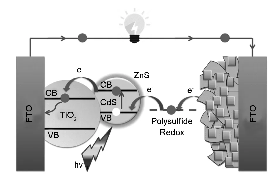
Fig. 4 A schematic representation of FTO/TiO2/CdS/ZnS QDSSC device assembled based on the CuxS/RGO CE.
The photovoltaic performance characteristics of CdS QDSSCs assembled with the different CEs were measured under simulated solar light illumination with a standard condition of AM 1.5G and an intensity of 100 mW/cm2. The obtained photocurrent density-photovoltage (J-V) characteristics are shown in Fig. 5(a), and the corresponding solar cell parameters of the tested QDSSCs, namelyJSC,VOC, FF, and PCE are summarized in Table 2. In consistent with the electrochemical measurements, the overall photovoltaic performances of QDSSCs with the different CuxS@RGO CEs are better than the cell based on RGO CE, with the best photovoltaic performance from the CuxS/RGO 100 CE. This clearly reflects the role of CuxS in improving the activity of RGO, and also the influence of the CuxS stoichiometric ratio of on the performance of CuxS/RGO as a cathode for QDSSCs.
Clearly seen from Table 2, the CdS QDSSCs fabricated based on CuxS/RGO 100 CE shows the highestJSCof 8.67 mA/cm2andVOCof 0.571 V, which is mainly ascribed to the preferred and fast reduction of Sx2-ions to S2-ions at the CuxS/RGO 100 CE surface. This gives rise to efficient restoration of CdS QDs back to the ground state by rapid hole scavenging from CdS valence band by rapid electron donation from the polysulfide electrolyte[7]. Hence, these high values ofJSCandVOCalong with an improved FF of 47.5% resulted in the outstanding high PCE of 2.36% achieved. This is mainly due to the suppression in the recombination rate of photogenerated electrons at the interface between the photoanode and the electrolyte upon using the superior catalytic CuxS/RGO 100 CE[30]. On the other side, only 1.57% of PCE was achieved from the CdS QDSSCs assembled with the Cu2S/brass CE, which is 33.5% lower than the cell based on CuxS/RGO 100 CE. This low performance is basically due to the obtained lower values ofVOCof 0.451 V and FF of 42.2%. Moreover, the QDSSCs based on the RGO CE shows the lowest PCE of 0.85% because of the low catalytic activity of the chemically reduced RGO, as clearly seen from the lowVOCand FF.
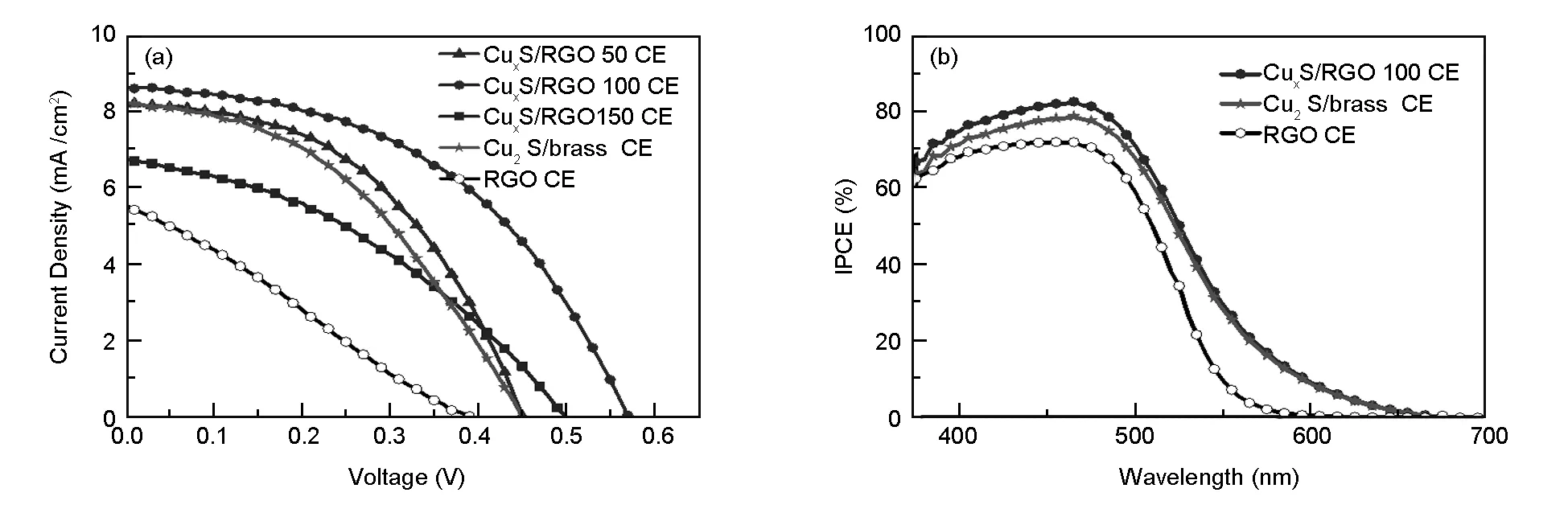
Fig.5 (a) J-V characteristic, (b) IPCE curves of CdS QDSSC assembled with the different CEs.
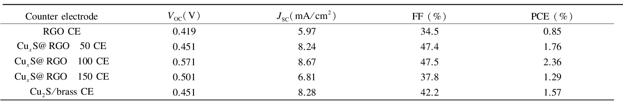
CounterelectrodeVOC(V)JSC(mA/cm2)FF(%)PCE(%)RGOCE0.4195.9734.50.85CuxS@RGO 50CE0.4518.2447.41.76CuxS@RGO 100CE0.5718.6747.52.36CuxS@RGO 150CE0.5016.8137.81.29Cu2S/brassCE0.4518.2842.21.57
The IPCE measurements were also performed to confirm the enhancement in the photovoltaic performance upon the application of our novel CuxS/RGO 100 CE[31]. The IPCE curves of CdS QDSSCs assembled with the different CEs as a function of incident wavelength are shown in Fig. 5(b). Compared to the obtained IPCE peak values of QDSSCs with the Cu2S/brass (IPCE=79.3%), and RGO (IPCE=72.5%) CEs, the cell assembled with the CuxS/RGO 100 CE shows the highest IPCE peak value of 83% at a wavelength of 465 nm. The results of IPCE data proves that a more efficient utilization of the photogenerated electrons using the CuxS/RGO 100 as a CE, which is in good agreement with the photovoltaic performance andJ-Vmeasurements.
The reproducibility of the highly photovoltaic performance obtained upon the application of CuxS/RGO 100 as a CE was investigated by fabricating and characterization of three QDSSC devices under the same experimental conditions. Fig. 6(a) shows theJ-Vcurves of the three assembled QDSSC devices. It can be seen that all the three cells show the high photovoltaic performance characteristics with nearly equal PCE (~2.29% ± 0.06%) values, which demonstrates the high reproducibility of the CuxS/RGO 100 CE for the QDSSC applications. Furthermore, as the stable operation under normal operating conditions is a prerequisite for practical solar cell devices, a photostability test of QDSSCs under standard operation condition was performed. The photostability of the QDSSCs was tested by monitoring the change in the short-circuit current under light soaking with continuous one-sun illumination for 180 min. As clearly shown in Fig. 6(b), the QDSSC with the CuxS/RGO 100 as the CE exhibits no apparent change inJSCduring 180 min, which clearly indicates an excellent photostability of the developed CE. The perfect photostability of the QDSSC device is directly related to the high chemical durability of the CuxS/RGO CE, resulting from wrapping CuxS nanocrystals by the chemically inert RGO sheets. In contrast, the QDSSC based on the Cu2S/brass CE did not withstand the 180 min photostability test. A very sharp decrease inJSCwas observed during the first hour of the test, and a complete failure of the cell occurred after 2 h of testing. The contamination of the electrolyte and photoanode by Cu2S released from the brass substrate due to the continuous reaction between the polysulfide and the brass is the main reason for this inferior stability[32,33].
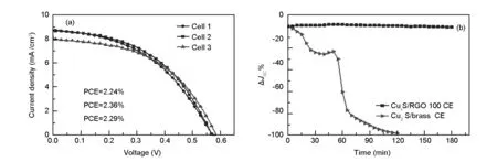
Fig. 6 (a) J-V characteristic curves of three CdS QDSSC devices fabricated with CuxS/RGO 100 CE, and (b) Percentage change in the JSC of CdS QDSSCs based on the CuxS/RGO 100CE and Cu2S/brass CEs under light soaking for 180 min.
4 Conclusions
We have demonstrated a new and simple method to prepare highly efficient and cost- effective CuxS/RGO CE for QDSSCs. The CuxS/RGO nanocomposites were synthesized by the facile one-step hydrothermal method, where the high-performance CEs were fabricated by coating CuxS/RGO ink directly on a FTO substrate using a drop-casting method. FE-SEM and XRD measurements show that the initial concentration of GO solution has a remarkable effect on the stoichiometry and morphology of the obtained CuxS nanocrystal. Electrochemical measurements reveal the effect of CuxS nanocrystal stoichiometry and particle size on the electrochemical activity of the fabricated CEs. The smaller the particle size and the higher covellite CuS content, the higher the superior electrochemical activity. The high performance is contributed by a large number of CuxS active sites and the rapid electron transport through the conductive graphene framework afforded by the CuxS/RGO 100 CE. The overall photovoltaic parameters of QDSSCs are greatly improved by using the novel CuxS/RGO 100 as a CE. A CdS QDSSC assembled with the CuxS/RGO 100 CE exhibits a highly stable and reproducible PCE of 2.36%, much higher than the PCE (1.57%) obtained with the state of the art Cu2S/brass CE. Thus, the developed CuxS/RGO 100 CE has a great potential for use in future QDSSCs owing to its high productivity and excellent stability.
Acknowledgements
The authors are grateful to Professor Kazunari Matsuda, Institute of Advanced Energy (IAE), Kyoto University and Professor A. Wakamiya, Institute for Chemical Research (ICR), Kyoto University, for their kind help and support for performing and finishing this work. The authors also gratefully acknowledge the Missions Sector-Higher Education Ministry, Egypt, for financial support through this work, and the Materials Science and Engineering Department at E-JUST.
[1] A Badawi. Tuning the energy band gap of ternary alloyed Cd1-xPbxS quantum dots for photovoltaic applications[J]. Superlattices Microstruct, 2016, 90: 124-131.
[2] A Badawi, N Al-Hosiny, S Abdallah. The photovoltaic performance of CdS quantum dots sensitized solar cell using graphene/TiO2working electrode[J]. Superlattices Microstruct, 2015, 81: 88-96.
[3] A Tubtimtae, T Hongto, K Hongsith, et al. Tailoring of boron-doped MnTe semiconductor-sensitized TiO2photoelectrodes as near-infrared solar cell devices[J]. Superlattices Microstruct, 2014, 66: 96-104.
[4] M Raja, N Muthukumarasamy, D Velauthapillai, et al. Enhanced photovoltaic performance of quantum dot-sensitized solar cell fabricated using Al-doped ZnO nanorod electrode[J]. Superlattices Microstruct, 2015, 80: 53-62.
[5] D M Li, L Y Cheng, Y D Zhang, et al. Development of Cu2S/carbon composite electrode for CdS/CdSe quantum dot sensitized solar cell modules[J]. Sol Energy Mater Sol Cells, 2014, 120: 454-461.
[6] I Hwang, K Yong. Counter electrodes for quantum-dot-sensitized solar cells[J]. Chem Electro Chem, 2015, 2(5): 634-653.
[7] J G Radich, R Dwyer, P V Kamat. Cu2S reduced graphene oxide composite for high-efficiency quantum dot solar cells. Overcoming the redox limitations of S2-/Sn2-at the counter electrode[J]. J Phys Chem Lett, 2011, 2(19): 2453-2460.
[8] K Meng, G Chen, K R Thampi. Metal chalcogenides as counter electrode materials in quantum dot sensitized solar cells: a perspective[J]. J Mater Chem A, 2015, 3: 23074-23089.
[9] H Zhang, H Bao, X Zhong. Highly efficient, stable and reproducible CdSe-sensitized solar cells using copper sulfide as counter electrodes[J]. J Mater Chem A, 2015, 3(12): 6557-6564.
[10] H Salaramoli, E Maleki, Z Shariatinia, et al. CdS/CdSe quantum dots co-sensitized solar cells with Cu2S counter electrode prepared by SILAR, spray pyrolysis and Zn-Cu alloy methods[J]. J Photochem Photobiol A Chem, 2013, 271: 56-64.
[11] C Venkata Thulasi-Varma, S S Rao, C S S P Kumar, et al. Enhanced photovoltaic performance and time varied controllable growth of a CuS nanoplatelet structured thin film and its application as an efficient counter electrode for quantum dot-sensitized solar cells via a cost-effective chemical bath deposition[J]. Dalt Trans, 2015, 44: 19330-19343.
[12] D Punnoose, H-J Kim, S Srinivasa Rao, et al. Cobalt sulfide counter electrode using hydrothermal method for quantum dot-sensitized solar cells[J]. J Electroanal Chem, 2015, 750: 19-26.
[13] V H Vinh Quy, J H Kim, S H Kang, et al. Enhanced electrocatalytic activity of electrodeposited F-doped SnO2/Cu2S electrodes for quantum dot-sensitized solar cells[J]. J Power Sources, 2016, 316: 52-59.
[14] J H Zeng, D Chen, Y F Wang, et al. Graphite powder film-supported Cu2S counter electrodes for quantum dot sensitized solar cells[J]. J Mater Chem C, 2015, 3: 12140-12148.
[15] S Hassan, M Suzuki, A A El-Moneim. Facile synthesis of MnO2/graphene electrode by two-steps electrodeposition for energy storage application[J]. Int J Electrochem Sci, 2014, 9(12): 8340-8354.
[16] E Ghoniem, S Mori, A Abdel-Moniem. Low-cost flexible supercapacitors based on laser reduced graphene oxide supported on polyethylene terephthalate substrate[J]. J Power Sources, 2016, 324: 272-281.
[17] A Hessein, F Wang, H Masai, et al. One-step fabrication of copper sulfide nanoparticles decorated on graphene sheets as highly stable and efficient counter electrode for CdS-sensitized solar cells[J]. Jpn J Appl Phys, 2016, 55(11): 112301.
[18] B Zheng, C Gao. Preparation of graphene nanoscroll/polyaniline composites and their use in high performance supercapacitors[J]. New Carbon Mater ials, 2016: 31(3): 315-320.
[19] C Xu, R Yuan, X Wang. Selective reduction of graphene oxide[J]. New Carbon Mater ials, 2014, 29(1): 61-66.
[20] L Liu, K P Annamalai, Y Tao. A hierarchically porous CuCo2S4/graphene composite as an electrode material for supercapacitors[J]. New Carbon Mater ials, 2016, 31(3): 336-342.
[21] H Zhang, H Bao, X Zhong. Highly efficient, stable and reproducible CdSe-sensitized solar cells using copper sulfide as counter electrodes[J]. J Mater Chem A, 2015, 3(12): 6557-6564.
[22] I Barceló, J M Campia, T Lana-Villarreal, et al. A solid-state CdSe quantum dot sensitized solar cell based on a quaterthiophene as a hole transporting material[J]. Phys Chem Chem Phys, 2012, 14(16): 5801-5807.
[23] X Wang, J Tian, C Fei, et al. Rapid construction of TiO2aggregates using microwave assisted synthesis and its application for dye-sensitized solar cells[J]. RSC Adv, 2015, 5(12): 8622-8629.
[24] G Wang, J Zhang, S Kuang, et al. The production of cobalt sulfide/graphene composite for use as a low-cost counter-electrode material in dye-sensitized solar cells[J]. J Power Sources, 2014, 269: 473-478.
[25] C S Kim, S H Choi, J H Bang. New insight into copper sulfide electrocatalysts for quantum dot-sensitized solar cells: Composition-dependent electrocatalytic activity and stability[J]. ACS Appl Mater Interfaces, 2014, 6(24): 22078-22087.
[26] M Najdoskia, I Grozdanova, C J Chunnilallb. Raman spectra of thin solid films of some metal sulfides[J]. J Mdecular structure, 1997, 410: 267-270.
[27] A G Milekhin, N A Yeryukov, L L Sveshnikova, et al. Combination of surface- and interference-enhanced Raman scattering by CuS nanocrystals on nanopatterned Au structures[J]. Beilstein J Nanotechnol, 2015, 6(1): 749-754.
[28] Z Li, F Gong, G Zhou, et al. NiS2/reduced graphene oxide nanocomposites for effi cient dye- sensitized solar cells[J]. J Phys Chem C, 2013, 117(13): 6561-6566.
[29] C V V M Gopi, S Srinivasa Rao, S K Kim, et al. Highly effective nickel sulfide counter electrode catalyst prepared by optimal hydrothermal treatment for quantum dot-sensitized solar cells[J]. J Power Sources, 2015, 275: 547-556.
[30] K Zhao, Z Pan, I Mora-Seró, et al. Boosting power conversion efficiencies of quantum-dot-sensitized solar cells beyond 8% by recombination control[J]. J Am Chem Soc, 2015, 137(16): 5602-5609.
[31] P V Kamat. Quantum Dot Solar Cells. Semiconductor nanocrystals as light harvesters[J]. J Phys Chem C, 2008, 112(48): 18737-18753.
[32] Y Jiang, X Zhang, Q-Q Ge, et al. Engineering the interfaces of ITO@Cu2S nanowire arrays toward efficient and stable counter electrodes for quantum-dot-sensitized solar cells[J]. ACS Appl Mater Interfaces, 2014, 6(17): 15448-15455.
[33] H Geng, L Zhu, W Li, et al. Electrochemical growth of FeS on three-dimensional carbon scaffold as the high catalytic and stable counter electrode for quantum dot-sensitized solar cells[J]. Electrochim Acta, 2015, 182: 1093-1100.