Algorithm and experiments of six-dimensional force/torque dynamic measurements based on a Stewart platform
2016-11-23WenKeDuFuzhouZhngXinzhi
Wen Ke,Du Fuzhou,*,Zhng Xinzhi
aSchool of Mechanical Engineering and Automation,Beihang University,Beijing 100083,China
bSchool of Mechanical and Aerospace Engineering,Kingston University,London SW15 3DW,UK
Algorithm and experiments of six-dimensional force/torque dynamic measurements based on a Stewart platform
Wen Kea,Du Fuzhoua,*,Zhang Xianzhib
aSchool of Mechanical Engineering and Automation,Beihang University,Beijing 100083,China
bSchool of Mechanical and Aerospace Engineering,Kingston University,London SW15 3DW,UK
Stewart platform(SP)is a promising choice for large component alignment,and interactive force measurements are a novel and significant approach for high-precision assemblies.The designed position and orientation(Pamp;O)adjusting platform,based on an SP for force/torquedriven(F/T-driven)alignment,can dynamically measure interactive forces.This paper presents an analytical algorithm of measuring six-dimensional F/T based on the screw theory for accurate determination of external forces during alignment.Dynamic gravity deviations were taken into consideration and a compensation model was developed.The Pamp;O number was optimized as well.Given the specific appearance of repeated six-dimensional F/T measurements,an approximate cone shape was used for spatial precision analysis.The magnitudes and directions of measured F/Ts can be evaluated by a set of standards,in terms of accuracy and repeatability.Experiments were also performed using a known applied load,and the proposed analytical algorithm was able to accurately predict the F/T.A comparison between precision analysis experiments with or without assembly fixtures was performed.Experimental results show that the measurement accuracy varies under different Pamp;O sets and higher loads lead to poorer accuracy of dynamic gravity compensation.In addition,the preferable operation range has been discussed for high-precision assemblies with smaller deviations.
1.Introduction
The alignment of large-scale and complex components,such as airframes,satellites,and rockets,typically involves a large number of assembly fixtures,which control the position and orientation(Pamp;O)of larger components in order to meet the accuracy requirement of the final assembly.Traditional fixed assembly fixtures can only be applied to the alignment of one specific large component.Even a small change in the shape or structure of the large component will lead to redesigning and remanufacturing a new fixed assembly fixture.With the rapid development of the assembly technology toward becoming digital,more flexible and intelligent,digital flexible alignment systems have gained popularity for large component alignment,consisting of both software and hardware.The software includes a control system,a measurement system,a simulation system,and a calculation system.The hardware includes a Pamp;O adjusting platform,digital measurement equipment,and an integrated control platform.The large components alignment process using a digital flexible alignment system has been transformed from the traditional process,based on manual fixtures and operations,to automatic alignment,which significantly improves aligning precision and efficiency.1
The Pamp;O adjusting platform(such as the electronic mating alignment system,automated positioning systems based on POGOs,and parallel adjusting platforms),as a key section of the large component alignment,can automatically adjusts the Pamp;O of large components.2In recent years,parallel robots have been widely used for Pamp;O adjustments of large-scale component assembly,due to their outstanding advantages including high stiffness,high load capacity,fast motion,and high positioning accuracy.3,4Being the most frequently used structure of parallel robots,Stewart platforms(SPs)are suitable for machining and manufacturing,5,6surgical operations,7simulator designing,8,9flexible and precise assembly of aircraft sections,10spacecraft Pamp;O adjustments,11and low-impact alignments.12An SP is composed of a moving platform and a base platform,which are connected with six stretchable limbs through spherical/universal joints.In the operation range,the 6-degrees-of-freedom(DOF)motion of the moving platform could be achieved by the motions of the six limbs as a whole.13,14
Currently,the main assembly strategy that is followed for a digital flexible alignment system is measurement aided assembly(MAA),which is based on geometrical control.15In order to direct and support the applications of advanced approaches in MAA for wing-fuselage alignment and realize the process integration and data fusion,a novel framework of measurement assisted assembly methodology has been proposed,based on key measurement.16Aiming to control the geometrical key characteristics and attain the best fit of Pamp;O,which is a key feature in MAA,an optimization algorithm based on key characteristics for large component assembly has been proposed.17Using different measurement systems to measure the coordinates of points,the uncertainty of measurement results was analyzed from uncertainty contributions and setup procedures.18,19With the improvement of manufacturing and processing accuracy,a phenomenon that the accuracy of the measurement system is lower than that of assembly design takes place.20In this case,it will not only lead to an assembly failure,but also cause unexpected damages of components.Thus the measurement and control of the interaction force between components have great significance for the quality of the final product.Since six-dimensional force/torque(F/T)sensors can measure three-dimensional forces and threedimensional torques with appropriate control techniques,they are commonly utilized to complete the force feedback loop control and high-precision assembly of components.The force measurement and control technology rely on two important parts:sensors and force control.
·Six-dimensional F/T sensors:Based on the elastomeric structure,six-dimensional F/T sensors can be divided into two groups:direct output type without coupling and indirect output type with coupling(including the SP structure).Structures of both types are fixed and unchangeable.Moreover,the isotropic configuration of a six-dimensional F/T sensor based on an SP,the task-oriented design method of a six-dimensional F/T sensor,and a six-dimensional F/T sensor have been introduced to complete peg-in-hole assembly tasks.21,22A six-beam sensor based on SP and the idea concept of ‘joint less’structure and beam sensors have been proposed to improve the precision and sensitivity in measuring a small F/T.23A six-dimensional heavy F/T sensor with high stiffness and good linearity based on SP has been presented.24Experimental results verified the feasibility and validity of the sensor by an established calibration platform.To summarize,six-dimensional F/T sensors have many types offorms and some advanced features.However,they are limited to the work environment and cannot be open-access designed for specific needs.Finally,they are very expensive.
·Force control techniques:A shape recognition algorithm based on a six-dimensional F/T sensor and a hole detection algorithm havebeen reported.25Experimentalresults showed that the two algorithms could complete the assembly of chamferless square peg-in-hole.The six-dimensional F/T sensor was employed to estimate the contact phases and design the assembling strategy to achieve force-guided robotic assembling.26–28The admittance characteristics for a force-guided robotic assembly and analytical derivations for different contact states were presented by Wiemer and Schimmels.29A modified control scheme for an SP with compensations for interaction force control and positional error recovery was introduced.30A novel strategy of the high-precision chamferless peg-hole insertion with a sixdimensional F/T sensor was introduced.31This strategy implemented the relation between a peg and a hole from the force sensor signal,and provided a wide range of initial conditions that affected the insertion.To summarize,a correct use of the interaction force can effectively achieve assembling.Finally,many control strategies have also been studied.
Following a literature review,traditional fixed assembly fixtures have been unable to meet the needs of large component alignment in a digital, flexible,and intelligent assembly process.On the contrary,the SP has gained popularity for its outstanding advantages in alignment of large-scale components.However,the measurement and control of the interaction forces between components should be considered.Therefore,a digital flexible alignment system with an SP based on six-dimensional F/T feedback and combined with force control techniques has been designed in this study.Due to the high manufacturing costs of six-dimensional F/T sensors and the required large size,they are not suitable for direct use in digital flexible alignment systems.Consequently,a Pamp;O adjusting platform based on an SP and force sensors has been designed,which can adjust the Pamp;O of a component and dynamically measure interactive forces.The platform uses six inexpensive force sensors placed in each limb to measure the forces of limbs and calculates the sixdimensional F/T based on measurement results.Moreover,combined with force control techniques,a precision analysis method of the six-dimensional F/T is proposed.
This paper takes into consideration multiple influential factors of the measurement accuracy of the interaction forces between components.Among the forces,gravity is of great research interest,and for the first time,this paper provides an analytical algorithm of a six-dimensional F/T with dynamic gravity compensation.The setup of the paper is as follows:Section 1 introduces the digital flexible assembly system and its significance,highlights the applications of the SP,and provides a new perspective and novel methods of large components alignment.Section 2 provides the analytical algorithm of a six-dimensional F/T,proposes a dynamic gravity compensation model based on the screw theory,and offers a parameter which is optimized through experiments.For the spatial precision analysis,Section 3 uses an approximate cone shape to evaluatetheaccuracy and repeatability ofthesixdimensional F/T.In Section 4,using the designed Pamp;O adjusting platform to verify the accuracy of the proposed algorithm and perform spatial precision experiments,relevant experimental data are analyzed and discussed.Section 5 concludes the paper and assesses the validity and limitations of the present algorithm and model.
2.Analytical algorithm of the six-dimensional F/T with dynamic gravity compensation
2.1.Overall research description
The overall study for calculating a six-dimensional F/T with dynamic gravity compensation can be depicted in the flowchart presented in Fig.1.The Pamp;O adjusting platform offers 6-DOF motion,due to the motions of six limbs as a whole,and the sixdimensional F/T is dynamically calculated by force sensors,which are placed in each limb to measure the forces of limbs.Moreover,due to the barycenter and gravity deviations of the large component,wrong calculation results will be derived.Thus,the dynamic gravity compensation is studied.
As shown in the left part offig.1,a traditional sixdimensionalF/T sensorisused to measure thesixdimensional F/T.The structural parameters of the sensor cannot be changed;hence,the measurement process is static.Since the lengths of the limbs remain unchanged after the initial setting,there are no sliding joints on the limbs.The sixdimensional F/T is calculated by measuring the forces of the limbs in o1-x1y1z1.As shown in the right part offig.1,the Pamp;O adjusting platform based on an SP is used to calculate the six-dimensional F/T.The length of the structural parameters is changed to adjust the Pamp;O of the component;hence,the calculation process is dynamic.Moreover,the barycenter and gravity of the component must be dynamically compensated.Then,the six-dimensional F/T is calculated by measuring the forces of the limbs based on the dynamic gravity compensation in o1-x1y1z1.
2.2.Analytical algorithm of a six-dimensional F/T based on an SP
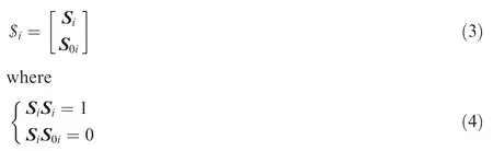
As presented in Fig.2,the Pamp;O adjusting platform based on an SP consists of a moving platform and a base platform,which are connected to each other with six limbs,adjustable in length through sliding joints.In the operation range,the 6-DOF motion of the moving platform could be achieved by the motions of the six limbs as a whole.Force sensors are placed in each limb to measure the force fiapplied to the limbs.Encoders are used to measure the length liof the limbs(i=1,2,...,6).The Cartesian coordinate system of o0-x0y0z0is located in the center of the top surface of the base platform,while the Cartesian coordinate system of o1-x1y1z1is located in the center of the bottom surface of the moving platform.The centers of the spherical joints are denoted as Aiand Bi.
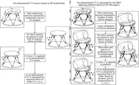
Fig.1 Overview of overall study for calculating a six-dimensional F/T with dynamic gravity compensation.
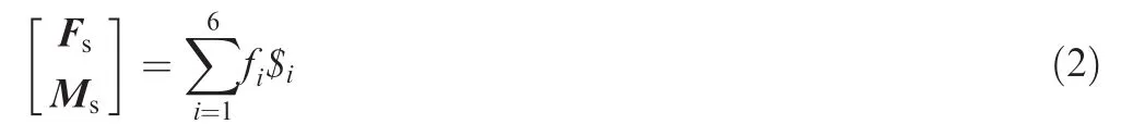
The external load[Fs,Ms]Tof the moving platform in o1-x1y1z1could be calculated by the measured fiand li.The six-dimensional F/T can be defined as follows:

where[Fs,Ms]Tis the calculation results,and fiand liare the measured forces and length data of the limbs,respectively.
Once the distance between Aiand Bi(limb length li)is set,the Pamp;O parameters{x,y,z,α,β,γ}between o1-x1y1z1and o0-x0y0z0could be solved by the newton iteration method.32Among the Pamp;O parameters,x,y,and z are the displacements of o1-x1y1z1with respect to o0-x0y0z0,and α, β,and γ are the rotation angles of o1-x1y1z1with respect to o0-x0y0z0.
The forceequilibrium equation could bedefined in o1-x1y1z1using the screw theory as follows:
where$iis the unit screw along the ith leg,and could be obtained by the following:
Siand S0ican be given by(as in Fig.2):
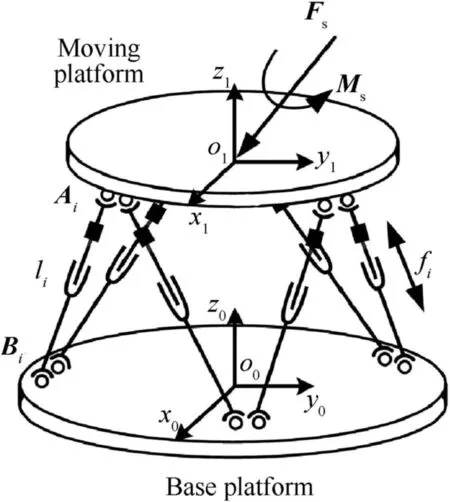
Fig.2 Schematic diagram of a flexible fixture based on an SP for F/T-driven assembly.
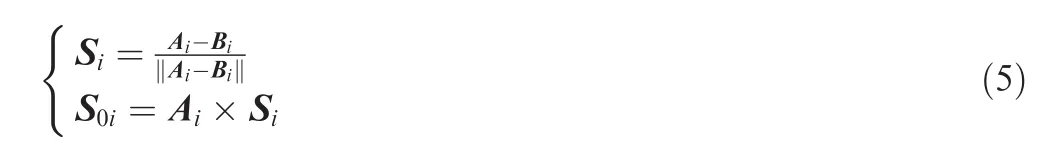
where Aiand Biare the coordinates in o1-x1y1z1.However,in the actual calculation,Aiis the position vector from o1-x1y1z1to the ith spherical joint and Biis the position vector from o0-x0y0z0to the ith universal joint.According to the Pamp;O parameters{x,y,z,α,β,γ},Eq.(5)can be rewritten as follows:
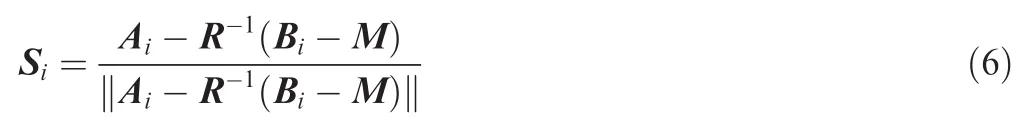
where


where R represents a rotation matrix and M represents a translation matrix.
Eq.(2)can be rewritten in the form of matrix equation as follows:
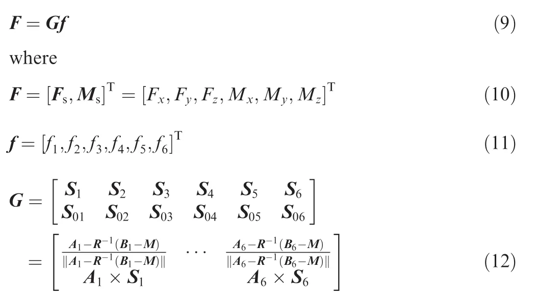
Hence,the external load[Fs,Ms]Tcan be calculated by Eq.(1).
2.3.Dynamic gravity compensation
During the assembly process,the moving platform of the SP,assembly fixtures,and components are relatively heavy and bulky,so their barycenter and gravity deviations,which are caused by manufacturing errors and installation errors,will lead to wrong calculation results of the six-dimensional F/T.Additionally,during the measurements,the adjustable motions of the six limbs would also lead to the coordinate changes of barycenter in o0-x0y0z0and the direction changes of gravity in o1-x1y1z1.To ensure the accuracy of the proposed analytical algorithm in Section 2.2,dynamic gravity compensation is needed.
2.3.1.Compensation model
The influential factors of the calculation results,which are the barycenter and gravity of the moving platform of the SP,assembly fixtures,and other components,cannot be ignored.This paper considers them as a rigid system.Eq.(9)can thus be rewritten as follows:
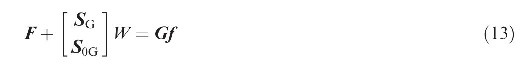
where W is the dimensionless value of the gravity,so it is not a vector.SGis the gravity unit vector of the said rigid system,so it is a 3-column vector.S0Gis the torque vector of SGwith respect to o1-x1y1z1,so S0Gis also a 3-column vector.
When the external load F=0,the six-dimensional F/T is caused by the gravity of the rigid system(as in Fig.3).The coordinate C=[x,y,z]Tindicates the barycenter of the rigid system in o1-x1y1z1.The gravity is divided into forces,along the x1-,y1-,and z1-axis(Fx,Fy,and Fz),and torques,about the x1-,y1-,and z1-axis(Mx,My,and Mz),simultaneously.The relation between three-dimensional forces and threedimensional torques is as follows:
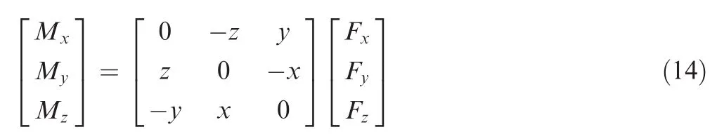
When the Pamp;O of the moving platform changes,Fx,Fy,Fz,Mx,My,and Mzalso change,while satisfying Eq.(14).According to the least square principle,C and W can be solved by the six-dimensional F/T under three different Pamp;O sets.The accuracy of the compensation model can be improved by more measurements under different Pamp;O sets.As an example,four measurements are performed here:
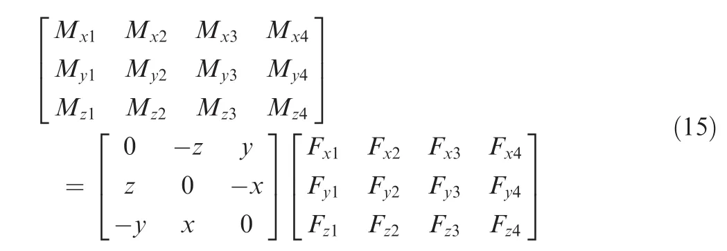
The resolving process of C and W from Eq.(15)is similar to that of the generalized inverse matrix ofmatrix consisting of real numbers,its generalized inverse matrix is of unique existence.When the Pamp;O changes,C and W of the rigid system do not differ in o1-x1y1z1,and the direction S=[0,0,-1]Tof the gravity does not vary in o0-x0y0z0,meaning:

Fig.3 Schematic diagram of the gravity of the rigid system in o1-x1y1z1.
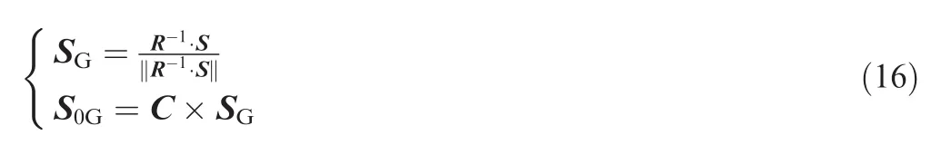
which could serve for the solution of Eq.(13).
For the preparation of a six-dimensional F/T measurement,experiments without external loads were carried out first,and the measured F/Ts could be used for the calculations of C and W using Eq.(15),after which C was substituted into Eq.(16)for the vector[SG,S0G]T.Then,for an arbitrary external load,the six-dimensional F/T in o1-x1y1z1could be obtained using Eq.(13)and the gravity of the rigid system could be dynamically compensated.
2.3.2.Parameter optimization
Without any external load,the measurement of the sixdimensional F/T should be equal to[0,0,0,0,0,0]Tin o1-x1y1z1.However,the analytical algorithm is affected by the gravity of the rigid system,resulting in errors for actual measurements,which must be compensated.According to Eq.(15),the accuracy of the model could be more efficiently compensated and improved by measurements under additional different Pamp;O sets.The determination of the Pamp;O number is essential for efficient dynamic gravity compensation.
Following the instructions of the Monte Carlo method,n Pamp;O sets were selected for experimental verification.Each set was repeated 200 times measurements,and the average values of the limb lengths and forces were obtained.A sixdimensional F/T can be calculated for each Pamp;O and can be used for the calculations of C and W using Eq.(15).Substituting C into Eq.(16),for the vector[SG,S0G]T,the gravity of the rigid system can be dynamically compensated by using Eq.(13).The designed Pamp;O adjusting platform applied in dynamic gravity compensation is presented in Fig.4.The parameters of the Pamp;O adjusting platform are listed in Table 1 and the graphical user interface(GUI)of data acquisition for dynamic gravity compensation is presented in Fig.5.
For the determination of the proper selection of the Pamp;O n number,another 50 Pamp;O sets were selected,and the sixdimensionalF/T afterdynamiccompensationcouldbe obtained.The fluctuations between the compensated F/T and[0,0,0,0,0,0]Twere calculated.For measurements repeating n times(n=3,4,...,24),the fluctuation range of the error is 3σ,where σ is the standard deviation.Experimental data are illustrated in Fig.6.
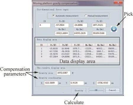
Fig.5 GUI of data acquisition for dynamic gravity compensation.
From Fig.6,it is noteworthy that the fluctuations after compensation were reduced with a higher n from the torques errors,indicating an enhanced compensation effect.The Fx,Fy,and Fzfluctuations show that the standard deviations vary along with n,yet within a small overall range,implying that the dynamic compensation offorces is of high stability and credibility.Regarding the Mx,My,and Mzfluctuations,the standard deviations decrease when n increases.In particular,the deviations of n=6 have been significantly reduced compared to those of n=3,indicating high converging rates of Mxand My.
For a stable and efficient compensation,the Pamp;O number was selected to be 18 for the following experiments.
3.Spatial precision analysis of the six-dimensional F/T
The force control techniques take the magnitude and direction of the measured F/T into consideration;hence,by measuring the six-dimensional F/T,the magnitude and direction of the measured F/T could be illustrated as an approximate cone shape,as demonstrated in Fig.7,which is utilized to evaluate the accuracy and repeatability of the six-dimensional F/T in the spatial precision analysis.
In an arbitrary coordinate system,six-dimensional F/T accuracy represents the deviation between an expected sixdimensional F/T and the average value of the measured F/T.The spatial precision standard in Fig.7 can be described using the following parameters:
·Force direction accuracy AFD:the angle between the expected direction and the central direction of measurements.
·Torque accuracy AMX,AMY,AMZ:the differences between the expected torques and the average torques of measurements(as AMY,in Fig.7).
In an arbitrary coordinate system,six-dimensional F/T repeatability stands for the variation in measurements for one expected six-dimensional F/T,which can be expressed by the following parameters:

Fig.7 Approximate cone shape for spatial precision analysis.
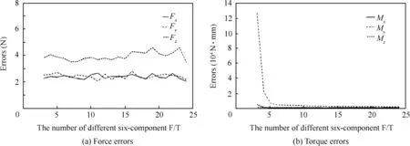
Fig.6 Fluctuation analysis of the six-dimensional F/T after dynamic compensation.
·Force direction repeatability RFD:half of the apex angle of the cone,formed by the measured directions.
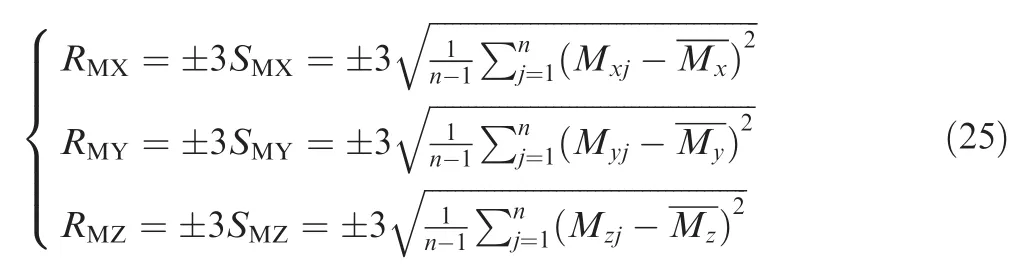
·Force magnitude repeatability RFM:spread of magnitude±3SFMabout the mean value m,where SFMis the standard deviation.
·Torque repeatability RMX,RMY,RMZ:spreads of torques±3SMX,±3SMY,±3SMZregarding the mean values Mx,My,Mz,where SMX,SMY,SMZare the standard deviations,respectively(as RMYin Fig.7).
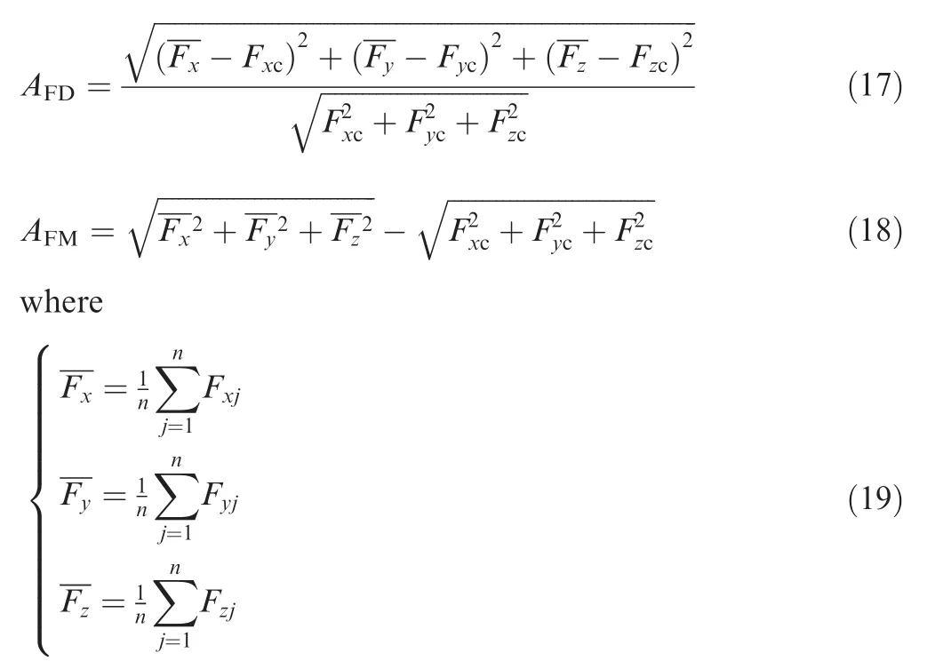
3.1.Force direction and magnitude accuracy
Let Fx,Fy,Fzbe the directional vectors of the center of the direction cluster for measurements that are repeated for n times,Fxc,Fyc,and Fzcthe directional vectors of the expected force,and Fxj,Fyj,and Fzjthe directional vectors of the jth measurement.
Then,the force direction accuracy AFDand the force magnitude accuracy AFMcan be calculated as follows:
“对!因为你走到下一条路,下个路口,只有下个山头,你才知道它下面的选择是怎么样,这里的风景跟前面不一样。有些机会是你以前想象不到的,但时间没有变,工作还是没有变。”紧凑的语速和敏捷的思维背后,我能感受到他的一丝疲惫。
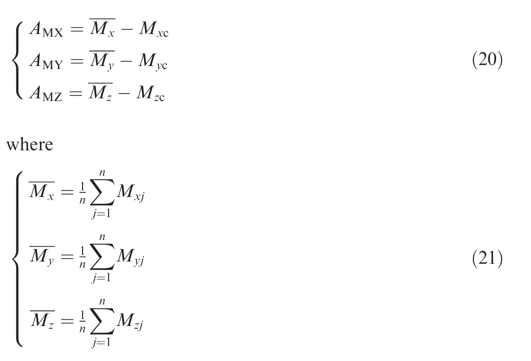
3.2.Torque accuracy
Let Mx,My,Mzbe the mean values of the torques measurements that are repeated for n times,Mxc,Myc,Mzcthe expected torques,and Mxj,Myj,Mzjthe torques of the jth measurement,respectively.The torque accuracy AMX,AMY,AMZcan be expressed as follows:
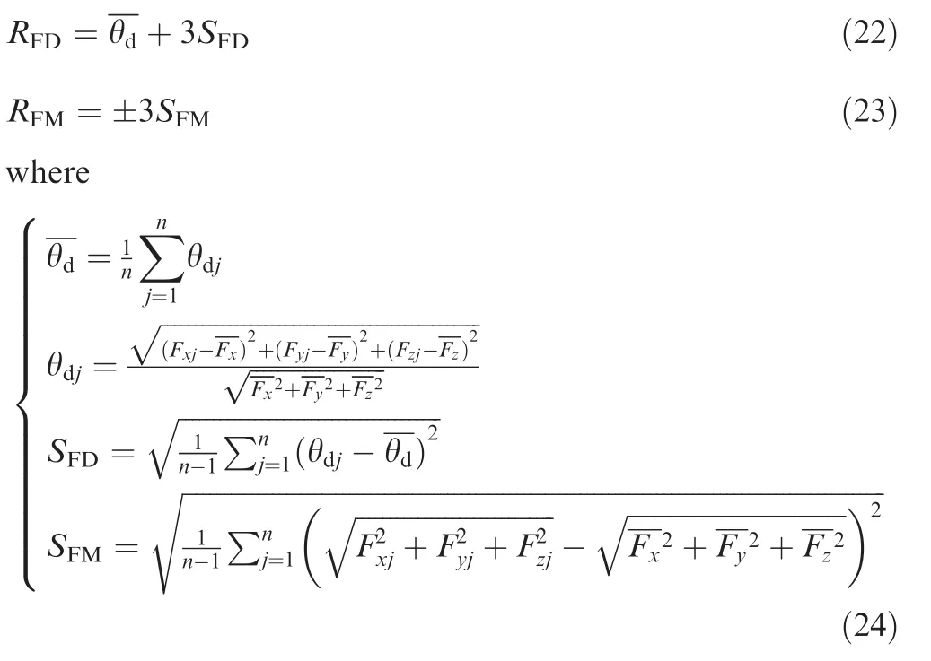
3.3.Force accuracy
With the aforementioned Fx,Fy,Fzand Fxj,Fyj,Fzj,the force direction repeatability RFDand the force magnitude repeatability RFMcan be de fined as follows:
3.4.Torque repeatability
The torque repeatability RMX,RMY,RMZcan be obtained by the following:
4.Experimental results and discussion
4.1.Measurement of a known applied load
The designed Pamp;O adjusting platform is presented in Fig.4.To measure a known applied load,three steps have been followed in this paper.Firstly,a known six-dimensional F/T is applied to the Pamp;O adjusting platform.The through-hole of the moving platform is used to hang the known load.In this paper, the coordinates of the through-hole are[302.874,-175.192,89.64]Tin o1-x1y1z1,the known load is 15 kg,and the Pamp;O is{0,0,0,0,0,0}.Hence,the value of the six-dimensional F/T can be calculated by the proposed algorithm and be expressed as [0,0,-150,26278.8,45431.1,0]Tin o1-x1y1z1.Secondly,measuring the load 1000 times repeatedly,under dynamic gravity compensation,1000 measurement results of the six-dimensional F/T can be obtained.Thirdly,the analytical predictions of the proposed algorithm are presented in Fig.8.The accuracy and repeatability analyses are listed in Tables 2 and 3,respectively.Finally,additional 1000 measurement results of the six-dimensional F/T are used to verify the validity of the calculation results and conclusions can be acquired.

Table 2 Accuracy analysis of the six-dimensional F/T.

Table 3 Repeatability analysis of the six-dimensional F/T.
From Fig.8,it is noteworthy that the proposed algorithm could accurately predict the forces and torques in consistency with the theoretical values.Together with the experimental data,the force direction accuracy AFDis 0.003 rad and the force direction repeatability RFDis 0.107+3×0.048 rad;the force magnitude accuracy AFMis 0.329 N and the force magnitude repeatability RFMis±3×13.668 N,which are ideal for the six-dimensional F/T measurements.Comparisons between Tables 2 and 3 could also lead to the conclusion that the accuracy and repeatability offorce were improved,compared to those of torque,which is attributed to the difference in their physical properties.For the force measurements,the errors could offset due to their directions.However,for the torque measurements,the deviations would be amplified by the arm offorce for experiments.
Measuring the load 1000 times repeatedly,under dynamic gravity compensation,1000 measurements ofthe sixdimensional F/T are all within the scopes of Tables 2 and 3.Thus,the method of the spatial precision analysis is considered as correct.
4.2.Precision analysis of measuring the six-dimensional F/T
Dynamic gravity compensation is critical for high-precision assembly and serves as an efficient tool for preliminary calibration before actual measurements.The designed Pamp;O adjusting platform based on an SP for F/T-driven alignment can adjust the Pamp;O,and dynamically measure interactive forces.However,the measurement accuracy of the six-dimensional F/T is different under different Pamp;O sets and the accuracy of dynamic gravity compensation presented in this paper could be affected by the gravity of the rigid system.In this section,experiments were carried out with the Pamp;O adjusting platform and spatial accuracy analyses were provided.Different Pamp;O parameters{x,y,z,α,β,γ}were discussed.A comparison between compensations with or without assembly fixtures was also presented.
The Pamp;O number n=18 has been selected based on Section 2.2.Under limb length variations,18 groups of sixdimensional F/T were obtained,and the barycenter C and the gravity value W could be determined.
4.2.1.Measuring the six-dimensional F/T without assembly fixtures
The Pamp;O adjusting platform without assembly fixtures is presented in Fig.4.The Pamp;O parameters of the moving platform were controlled for a motion of a single degree offreedom.Without assembly fixtures,the gravity value of the rigid system is 773.16 N(n=18).The moving range in x,y,and z directions is±40 with 10 mm variation for each measurement.The angle range is±5°with 1°variation for each measurement.For every change in Pamp;O parameters,500 groups of the six-dimensional F/T were measured.The average F/T and relevant results are illustrated in Fig.9.
Fig.9(a)and(b)displays the F/T distribution of the Pamp;O adjusting platform without assembly fixtures moving along the x,y,and z directions.Fig.9(c)and(d)displays the F/T distribution of the Pamp;O adjusting platform without assembly fixtures rotating around the x,y,and z directions.The location of the ball in Fig.9(a)represents the control position,while in Fig.9(c)the control orientation.The color bar on the right stands for the value of the measured force,with red areas being higher.The arrow of the ball shows the direction of the measured force.Fig.9(b)and(d)presents the torque variations with respect to the pose parameters.Details about the black lines,markers,and line styles are listed in the legend.
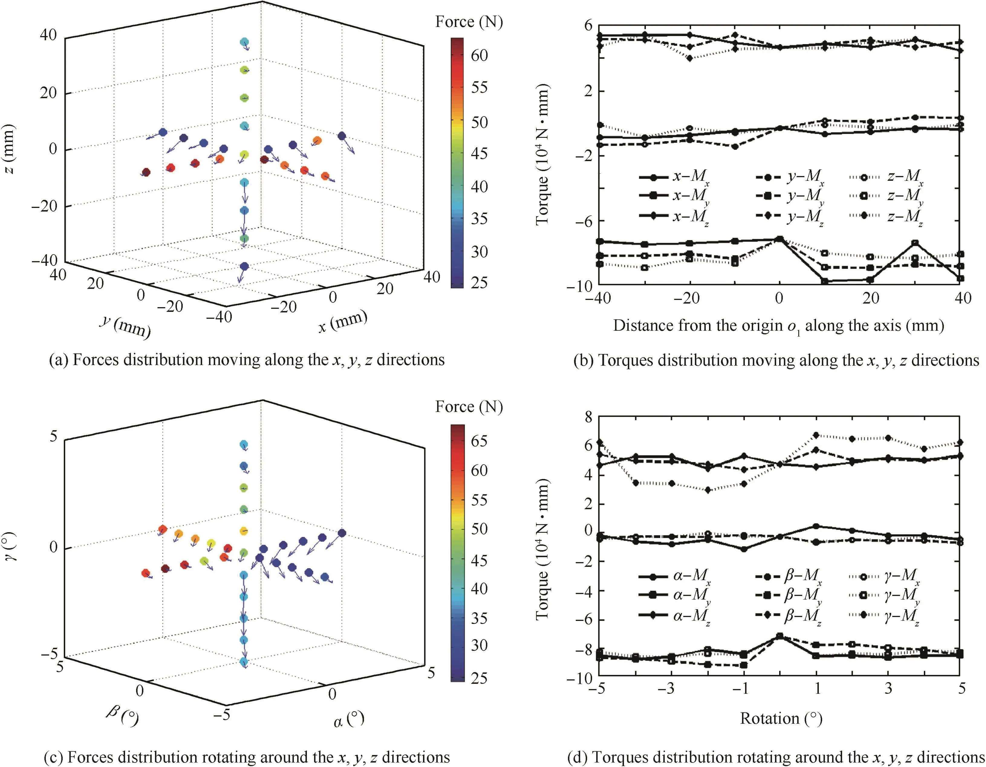
Fig.9 Experimental results of measuring the six-dimensional F/T without assembly fixtures.
From Fig.9(a)and(c),it can be observed that when the Pamp;O adjusting platform is moving along the x,y,and z directions without rotations,the deviations in the z direction are much smaller,compared to those in the other two directions.When the Pamp;O adjusting platform is moving in the range of x≥0 or y≥0,the deviations are smaller,and the force magnitude accuracy AFMis 30–35 N.The measured deviations increase when x decreases or y increases,and the biggest deviation is 60 N for x=-40 mm.When the Pamp;O adjusting platform is rotating around the x,y,and z directions,the deviations around the z direction are much smaller,compared to those around the other two directions.The deviations are smaller for α ≥ 0 or β ≤ 0,and the force magnitude accuracy AFMis 30–35 N.The biggest deviation appears at α =-5°and its force magnitude accuracy AFMis 65 N.The force vectors are all heading to the-x and-y directions,which indicates that a directional compensation could be made in the future to improve the accuracy of the algorithm.
From Fig.9(b)and(d),it can be observed that when the Pamp;O adjusting platform is moving along the x,y,and z directions without rotations,the torque accuracy AMXshows enhanced compensation with smaller deviations.When the Pamp;O adjusting platform without assembly fixtures is rotating around the x,y,and z directions,the torque accuracy AMXshows enhanced compensation with smaller deviations.
4.2.2.Measuring the six-dimensional F/T with assembly fixtures The Pamp;O adjusting platform with assembly fixtures is presented in Fig.10.The Pamp;O parameters of the moving platform were controlled for a single degree offreedom of motion.Without assembly fixtures,the gravity value of the rigid system is 1912.09 N(n=18).The moving range in the x,y,and z directions is±30,with 10 mm variation for each measurement.The angle range is±3°with 1°variation for each measurement.For every change in Pamp;O parameters,500 groups of the six-dimensional F/T were measured.The average F/T and relevant results are illustrated in Fig.11.

Fig.10 Pamp;O adjusting platform with assembly fixtures.
Fig.11(a)and(b)displays the F/T distribution of the Pamp;O adjusting platform with assembly fixtures moving along the x,y,and z directions,while Fig.11(c)and(d)displays the F/T distribution of the Pamp;O adjusting platform with assembly fixtures rotating around the x,y,and z directions.The location of the ball in Fig.11(a)represents the control position,while in Fig.11(c)the control orientation.The color bar on the right stands for the value of the measured force,with red areas being higher.The arrow of the ball shows the direction of the measured force.Fig.11(b)and(d)shows the torque variations with respect to the pose parameters.Details about the black lines,markers,and line styles are listed in the legend.
From Fig.11(a)and(c),it can be observed that when the Pamp;O adjusting platform with assembly fixtures is moving along the x,y,and z directions without rotations,the deviations in the z direction are much smaller,compared to those in the other two directions.When the Pamp;O adjusting platform is moving in the range of x≥0 or y≥0,the deviations are smaller,and the force magnitude accuracy AFMis 30–55 N.The measured deviations increase when x decreases or y increases,and the highest deviation is 80 N for y=-15 mm.When the Pamp;O adjusting platform is rotating around the x,y,and z directions,the deviations around the z direction are much smaller,compared to those of the other two directions.The deviations are smaller for α ≥ 0 or β ≤ 0,and the force magnitude accuracy AFMis 30–55 N.The biggest deviation appears at α =-3°and its force magnitude accuracy AFMis 65 N.The force vectors are all heading to the-x and-y directions,which indicate that a directional compensation could be made in the future to improve the algorithm’s accuracy.
From Fig.11(b)and(d),it can be observed that when the Pamp;O adjusting platform is moving along the x,y,and z directions without rotations,the torque accuracy AMXshows enhanced compensation with small deviations.When the Pamp;O adjusting platform with assembly fixtures is rotating around the x,y,and z directions,the torque accuracy AMXshows enhanced compensation with small deviations as well.
Comparisons between Sections 4.1 and 4.2 lead to the conclusion that the measurement accuracy of the six dimensional F/T is different under different Pamp;O sets.Therefore,a preferable operation range of the Pamp;O adjusting platform can be selected for high-precision assembly with smaller deviations.The accuracy of measuring the six-dimensional F/T with assembly fixtures is inferior to that observed without assembly fixtures,and the deviations are higher.This is attributed to the weight difference between the assembly fixtures and the moving platform.In this case,the assembly fixtures are twice as heavy as the moving platform,which lowers the accuracy of dynamic gravity compensation as well as the coupling effect of the six-dimensional F/T in the analytical algorithm.
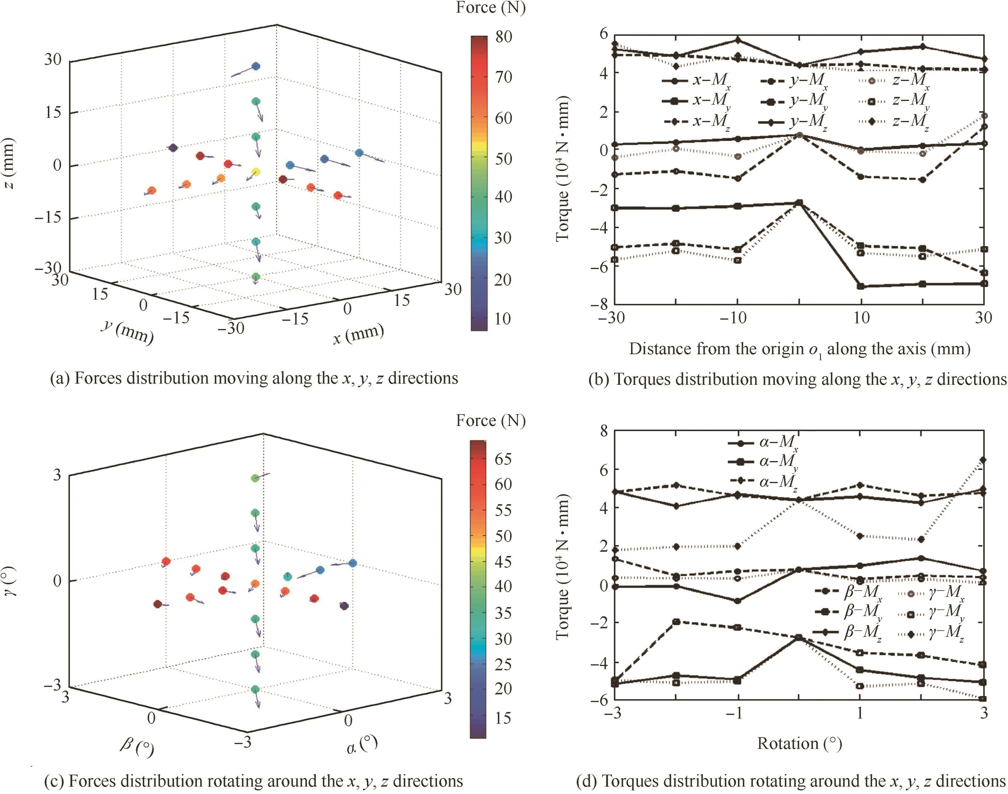
Fig.11 Experimental results of measuring the six-dimensional F/T with assembly fixtures.
4.3.F/T-driven alignment of large components
Experiments of the F/T-driven alignment for large components were performed on the designed digital flexible alignment system using aerospace products(as in Fig.12),and the alignment process can be described by the flowchart shown in Fig.13.Firstly,according to the precision analysis results of Section 4.2,the threshold value of the six-dimensional F/T could be obtained.In the experiment,the threshold value of the force magnitude was 60 N,and the threshold value of the torque magnitude was 25 N·m.Secondly,an operator judged the direction of the applied force by visual,and then an external force was applied to the Pamp;O adjusting platform by the operator.Thirdly,the six-dimensional F/T was calculated in real time by dynamic gravity compensation.Fourthly,intention recognition methods were designed through the threshold value,the direction and magnitude of the force,and the torque.In the end,the Pamp;O adjusting platform adjusted the Pamp;O of the large component to follow the intentions of the operator.
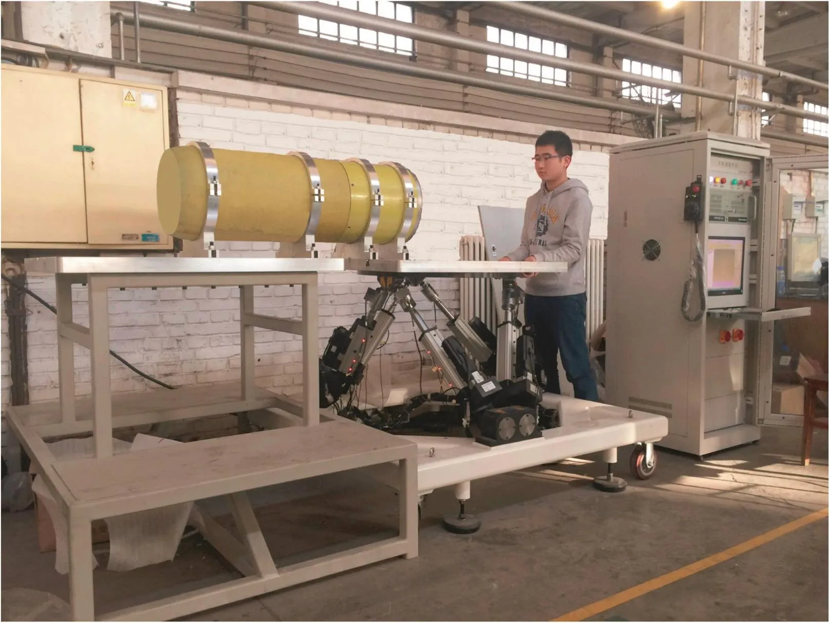
Fig.12 Alignment system of large components for F/T-driven assembly.
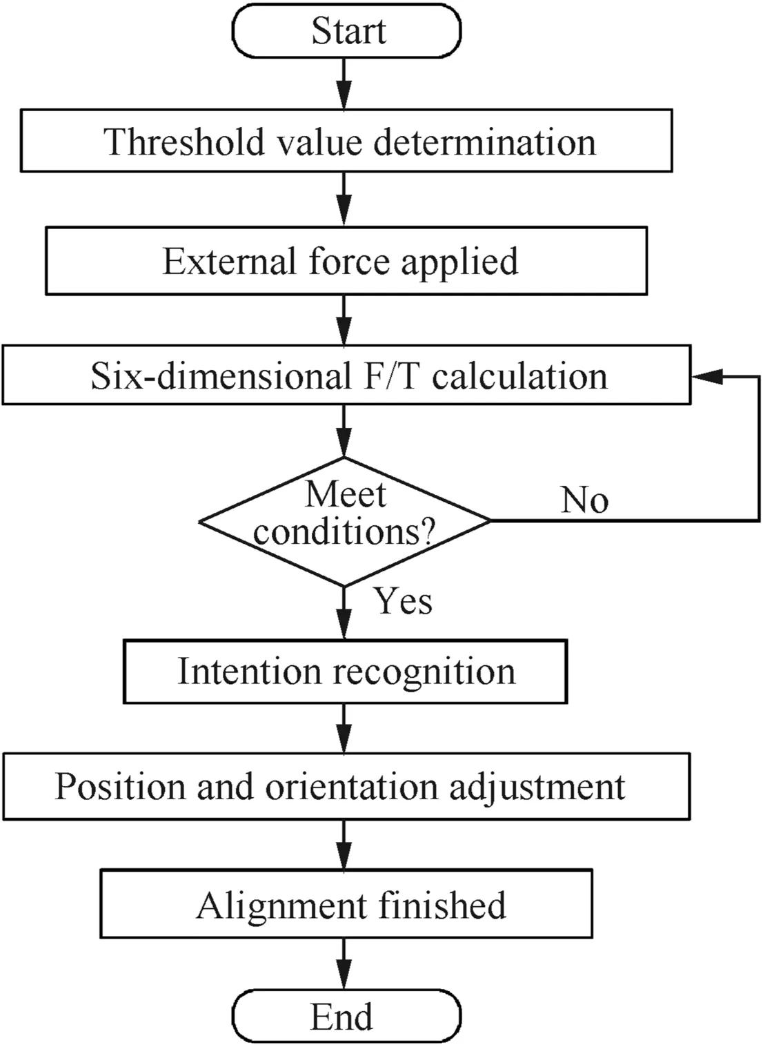
Fig.13 Flowchart of the F/T-driven alignment.
In the above experiments,the alignment process was completed successfully.The experimental results proved that the precision analysis of the six-dimensional F/T was correct and effective,and the intention recognition was correct.The alignment process met the real-time requirements.The analytical algorithm and precision analysis of the six-dimensional F/T based on the Pamp;O adjusting platform laid the foundation for F/T-driven alignment of large components.
5.Conclusions
The Pamp;O adjusting platform can dynamically measure interactive forces.This paper provides an analytical algorithm of the interaction forces between components and takes into consideration dynamic gravity deviations as influential factors.The relevant experimental results show that the proposed analytical algorithm can evaluate gravity deviations and make reliable compensations.The contributions of the paper are summarized as follows:
(1)An analytical algorithm of the six-dimensional F/T based on the screw theory is proposed for accurate determination of external forces during high-precision alignment.Dynamic gravity deviations are taken into consideration and a precise compensation model is provided.Barycenter coordinates and gravity directions are discussed in details.Meanwhile,the choice of the Pamp;O number is optimized for a stable and efficient compensation through experiments.
(2)An approximation cone shape is used for spatial precision analysis.Given the specific appearance of the repeated six-dimensional F/T measurements,the magnitudes and directions of the measured F/T could be evaluated by a set of standards,regarding accuracy and repeatability.
(3)Known applied load measurement experiments have been performed on the Pamp;O adjusting platform based on an SP for F/T-driven alignment,and relevant experimental data adequately prove that the proposed analytical algorithm could accurately predict the F/T with small deviations.Precision analysis experiments have been performed on the Pamp;O adjusting platform(without or with assembly fixtures),and relevant experimental data adequately prove that the measurement accuracy of the six-dimensional F/T is different under different Pamp;O sets.Higher loads lead to poorer accuracy of dynamic gravity compensation.In addition,the preferable operation range is discussed for high-precision alignment with smaller deviations.Based on the above analysis,the experiments off/T-driven alignment for large components have been completed successfully.
(4)Interactive force measurements are novel and significant for high-precision assembly,and the present algorithm could fulfill accurate force determination and provide satisfactory dynamic gravity compensation.Measuring the six-dimensional F/T could be further improved with higher motion control of the moving platform or more accuratemeasurementsofforcesor limb lengths.Besides,the coupling effect for the Pamp;O parameters,varying in synchronization and force control techniques,should be studied in future research.
Acknowledgments
This study was co-supported by the National Defense Basic Scientific Research(No.A2120132007)and the Fund of National Engineering and Research Center for Commercial Aircraft Manufacturing(No.SAMC14-JS-15-055).
Appendix A.Supplementary material
Supplementary data associated with this article can be found,in the online version,at http://dx.doi.org/10.1016/j.cja.2016.10.015.
1.Mei ZY,Maropoulos PG.Review of the application offlexible,measurement-assisted assembly technology in aircraft manufacturing.Proc IME B J Eng Manuf 2014;228(10):1185–97.
2.Chen ZH,Du FZ,Tang XQ.Research on uncertainty in measurement assisted alignment in aircraft assembly.Chin J Aeronaut 2013;26(6):1568–76.
3.Yao R,Zhu WB,Huang P.Accuracy analysis of Stewart platform based on interval analysis method.Chin J Mech Eng 2013;26(1):29–34.
4.Rosenzveig V,Briot S,Martinet P,Ozgur E,Bouton N.A method for simplifying the analysis of leg-based visual servoing of parallel robots.IEEE International Conference on Roboticsamp;Automation(ICRA);May 31–June 7;Hong Kong,China;2014.
5.Pedrammehr S,Mahboubkhah M,Khani N.A study on vibration of Stewart platform-based machine tool table.Int J Adv Manuf Technol 2013;65(5):991–1007.
6.Denkenaa B,Holza C,Abdellatifb H.Model-based control of a hexapod with linear direct drives.Int J Comput Integr Manuf 2006;19(5):463–72.
7.Dalvand MM,Shirinzadeh B.Motion control analysis of a parallel robot assisted minimally invasive surgery/microsurgery system(PRAMiSS).Robot Comput-Int Manuf 2013;29(2):318–27.
8.Tang F.Development of an engineering simulator for armored vehicle.International conference on Automation,Mechanical Control and Computational Engineering;Apr 24–26;Jinan,China;2015.
9.Pisla A,Itul T,Pisla D,Szilaghyi A.Considerations upon the influence of manufacturing and assembly errors on the kinematic and dynamic behavior in a flight simulator Stewart-Gough platform.Mech,Transm Appl:Mech Mach Sci 2012;3:215–23.
10.Lochte C,Dietrich F,Raatz A.A parallel kinematic concept targeting at more accurate assembly of aircraft sections.Intell Robot Appl 2011;7101:142–51.
11.Xu YF,Yuan JR,Zhao J,Zhao YB.Robust attitude control and simulation of a Stewart spacecraft.The 27th Chinese Control and Decision Conference;May 23–25;Qingdao,China;2015.
12.Zhao H,Zhang SY,Chen XD.Compliant force control in space docking.Proceedings of the 2007 IEEE International conference on mechatronics and automation;Aug 5–8;Harbin,China;2007.
13.Zhang GQ,Du JJ,To S.Calibration of a small size hexapod machine tool using coordinate measuring machine.Proc IME E J Process Mech Eng 2014;230(3):1989–96.
14.Zhou WY,Chen WY,Liu HD.A new forward kinematic algorithm for a general Stewart platform.Mech Mach Theory 2015;87:177–90.
15.Jamshidi J,Kayani A,Iravani P,Summers MD.Manufacturing and assembly automation by integrated metrology systems for aircraft wing fabrication.Proc IME B J Eng Manuf 2010;224(1):25–36.
16.Chen ZH,Du FZ,Tang XQ,Zhang X.A framework of measurement assisted assembly for wing-fuselage alignment based on key measurement characteristics.Int J Manuf Res 2015;10(2):107–28.
17.Zheng LY,Zhu XS,Liu RW,Wang YW,Maropoulos PG.A novel algorithm of posture best fit based on key characteristics for large components assembly.Procedia CIRP 2013;10:162–8.
18.Galetto M,Mastrogiacomo L.Analysing uncertainty contributions in dimensional measurements of large-size objects by ultrasound sensors.Int J Comput Integr Manuf 2014;27(1):36–47.
19.Ferria C,Mastrogiacomob L,Farawayc J.Sources of variability in the set-up of an indoor GPS.Int J Comput Integr Manuf 2010;23(6):487–99.
20.Muelaner JE,Cai B,Maropoulos PG.Large-volume metrology instrument selection and measurability analysis.Proc IME B J Eng Manuf 2010;224(6):853–68.
21.Yao JT,Zhang HY,Zhu JL,Xu YD,Zhao YS.Isotropy analysis of redundant parallel six-axis force sensor.Mech Mach Theory 2015;91:135–50.
22.Yao JT,Li WJ,Zhang HY,Xu YD,Zhao YS.Task-oriented design method and experimental research of six-component force Sensor.Intell Robot Appl 2014;8917:1–12.
23.Dwarakanath TA,Bhutani G.Beam type hexapod structure based six component force-torque sensor.Mechatronics 2011;21(8):1279–87.
24.Liu W,Li Q,Jia ZY,Jiang E.Design and experiment of a parallel six-axis heavy force sensor based on Stewart structure.Sensors Transd 2013;151(4):54–62.
25.Kim YL,Song HC,Song JB.Hole detection algorithm for chamferless square peg-in-hole based on shape recognition using F/T sensor.Int J Prec End Manuf 2014;15:425–32.
26.Jasim IF,Plapper PW.Contact-state monitoring offorce-guided robotic assembly tasks using expectation maximization-based Gaussian mixtures models.Int J Adv Manuf Technol 2014;73(5):623–33.
27.Shirinzadeh B,Zhong Y,Tilakaratna PDW,Tian YL,Dalvand MM.A hybrid contact state analysis methodology for roboticbased adjustment of cylindrical pair.Int J Adv Manuf Technol 2011;52(1):329–42.
28.Park DI,Park C,Do H,Choi T,Kyung JH.Assembly phase estimation in the square peg assembly process.The 12th International Conference on Control,Automation and Systems;Oct 17–21;JeJu Island,Korea;2012.
29.Wiemer SC,Schimmels JM.Optimal admittance characteristics for planar force-assembly of convex polygonal parts.2012 IEEE International Conference on Robotics and Automation;May 14–18;Saint Paul,MN,USA;2012.
30.Bera TK,Merzouki R,Bouamama BO,Samantaray AK.Force control in a parallel manipulator through virtual foundations.Proc IME I J Syst Control Eng 2012;226(8):1088–106.
31.Qiao H,Dalay BS,Parkin RM.Robotic peg-hole insertion operations using a six-dimensional force sensor.Proc IME C J Mech Eng Sci 1993;207:289–305.
32.Geng MC,Zhao TS,Wang C,et al.The study of the direct position analysis of parallel mechanism based on quasi-newton method.J Mech Eng 2015;51(9):28–36[Chinese].
Du Fuzhou is an associate professor and M.S.advisor in the School of Mechanical Engineering and Automation at Beihang University.His main research interests are measurement-assisted assembly,quality management,and quality engineering.
31 March 2016;revised 26 April 2016;accepted 16 August 2016
Available online 21 October 2016
Dynamic gravity compensation;
F/T-driven alignment;
Precision analysis;
Pamp;O adjusting platform;
Six-dimensional F/T
Ⓒ2016 Chinese Society of Aeronautics and Astronautics.Production and hosting by Elsevier Ltd.This is anopenaccessarticleundertheCCBY-NC-NDlicense(http://creativecommons.org/licenses/by-nc-nd/4.0/).
*Corresponding author.Tel.:+86 10 82316795.
E-mail addresses:rongyu_wen@163.com(K.Wen),du_fuzhou@163.com(F.Du),X.Zhang@kingston.ac.uk(X.Zhang).
Peer review under responsibility of Editorial Committee of CJA.
Production and hosting by Elsevier
http://dx.doi.org/10.1016/j.cja.2016.10.015
1000-9361Ⓒ2016 Chinese Society of Aeronautics and Astronautics.Production and hosting by Elsevier Ltd.
This is an open access article under the CC BY-NC-ND license(http://creativecommons.org/licenses/by-nc-nd/4.0/).
杂志排行

CHINESE JOURNAL OF AERONAUTICS的其它文章
- Analysis of swirling flow eff ects on the characteristics of unsteady hot-streak migration
- Implicit discontinuous Galerkin method on agglomerated high-order grids for 3D simulations
- Design and implementation of rigid-flexible coupling for a half-flexible single jack nozzle
- Dynamic simulation of aerial towed decoy system based on tension recurrence algorithm
- A quasi-one-dimensional model for hypersonic reactive flow along the stagnation streamline
- An experimental investigation on static directional stability