Cutting tool temperature prediction method using analytical model for end milling
2016-11-23WuBohiCuiDiHeXiodongZhngDinghuTngKi
Wu Bohi,Cui Di,He Xiodong,Zhng Dinghu,*,Tng Ki
aLaboratory of Contemporary Design and Integrated Manufacturing Technology,Ministry of Education,Northwestern Polytechnical University,Xi’an 710072,China
bHong Kong University of Science and Technology,Hong Kong,China
Cutting tool temperature prediction method using analytical model for end milling
Wu Baohaia,Cui Dia,He Xiaodonga,Zhang Dinghuaa,*,Tang Kaib
aLaboratory of Contemporary Design and Integrated Manufacturing Technology,Ministry of Education,Northwestern Polytechnical University,Xi’an 710072,China
bHong Kong University of Science and Technology,Hong Kong,China
Dramatic tool temperature variation in end milling can cause excessive tool wear and shorten its life,especially in machining of difficult-to-machine materials.In this study,a new analytical model-based method for the prediction of cutting tool temperature in end milling is presented.The cutting cycle is divided into temperature increase and decrease phases.For the temperature increase phase,a temperature prediction model considering real friction state between the chip and tool is proposed,and the heat flux and tool-chip contact length are then obtained through finite element simulation.In the temperature decrease phase,a temperature decrease model based on the one-dimension plate heat convection is proposed.A single wire thermocouple is employed to measure the tool temperature in the conducted milling experiments.Both of the theoretical and experimental results are obtained with cutting conditions of the cutting speed ranging from 60 m/min to 100 m/min,feed per tooth from 0.12 mm/z to 0.20 mm/z,and the radial and axial depth of cut respectively being 4 mm and 0.5 mm.The comparison results show high agreement between the physical cutting experiments and the proposed cutting tool temperature prediction method.
1.Introduction
Cutting heat is a fundamental physical phenomenon in machining and causes high temperature in local cutting zone,which results in many serious problems,including excessive toolwear, shortened tool life,and low machining accuracy.1–3End milling,which plays a critical role in manufacturing,has been extensively employed to finishing-cut parts of planar or curved shapes,as well as in rough machining.During an end milling process,enormous heat is produced because of the severe deformation of metal in the cutting zone and intensive friction in the chip-tool interface,especially for difficult-to-cut materials.The resulting excessive temperature inevitably worsens the tool wear and shortens its life,while atthesametimedetrimentsthesurfaceintegrityand machining quality.Understandably,it is necessary to study the temperature of cutting tool in order to improve the cutting condition in end milling.
There are many theoretical or experimental research works on interrupted cutting temperature,especially on end milling temperature.Radulescu and Kapoor4proposed an analytical model to predict the tool temperature field in the metal cutting process,which can be applied to both continuous and interrupted three-dimensional cutting.A time-dependent heat flux model was introduced to precisely represent the heating and cooling cycle in interrupted cutting.Stephen and Ali5analyzed tool temperature in interrupted cutting,both theoretically and through physical experiments.In their work,a theoretical model of semi-infinite rectangular corner heated by heat flux varying on time with different spacious distributions is employed to investigate the tool temperature distribution;the theoretical results are compared with the measurement resultsfrom infrared and tool-chip thermocouple.Lin6researched the tool-workpiece interface temperature problem in end milling by an inverse heat conduction approach,where the machine surface temperature measured by IR pyrometer is regarded as a boundary condition and an inverse finite element method is employed to estimate the tool-work interface temperature.Ueda et al.7used a two-color pyrometer to measure the temperature of tool flank face in high speed milling and investigated the effect of cutting parameters on temperature at a carbide tool flank face.The results show that the cutting speed is the most important factor in causing the temperature rise.Lazoglu and Altintas8proposed a temperature prediction model of the tool and chip in continuous machining and for time varying milling processes,based on the finite difference method.Firstly,a heat transfer model between the chip and tool rake face is employed to study the steady cutting operation,especially the orthogonal cutting.Then this model is extended to analyze a time-varying milling process considering the chip thickness varying with time.Sato et al.9,10invented an infrared radiation pyrometer with two optical fibers connected by a fiber coupler to measure the chip-tool interface temperature in end milling with brittle CBN tool.Their method is proved very practical for measuring the chip-tool temperature during chip formation.Later they used the measurement equipment to study the cyclic temperature variation beneath the rake face of tool in end milling,and compared the measurement results with the theoretical results obtained by the same theoretical model with Stephen and Ali.The comparison results show good agreement and it is validated that the temperature variation in up milling is inverse with that of down milling.Coz et al.11proposed a temperature measuring system for rotating tools that is made of a thermocouple integrated into the milling or drilling tool near the cutting edge and a wireless transmission unit and data conditioning system incorporated into the tool-holder.Jen et al.12obtained a numerical solution of nonlinear heat conduction by a volume control method to study the time-varying cutting temperature.Yang and Zhu13analyzed the cutting temperature in milling process of titanium alloy Ti6Al4V by a finite element model of helix double-edge cutting based on a new material constitutive model.Their analysis results suggest that the temperature at the rake face is higher than that on the flank and the high temperature is closer to the cutting edge.Jen et al.14proposed a temperature prediction model applied under transient conditions,which improved Stephenson’model by a fixed-point iteration process in quasi-steady energy partitioning.Feng et al.15analyzed the workpiece temperature by a heat conduction model based on the fundamental characteristics of the milling process.Specifically,the method of weight particle swarm optimization was used to evaluate the heat flux.Their experimental results on AISI1045 show that the global maximum and minimum heat are 2.856× 10⁶W/(m2·°C)and 2.823×10⁶W/(m2·°C)respectively;further,the interfacial heat flux was apparently divided into three non-linear stages.Cui et al.16analyzed transient average temperature in face milling.Chen et al.17investigated heat flux and temperature distribution on tool-work interface based on a three-dimension transient model of inverse heat conduction in high speed milling process.
Notwithstanding many valuable results aforementioned,the actual friction state of the tool-chip interface and the temperature dropping phase are not considered in these studies,resulting in inaccuracy of the analytical models of the cutting temperature.To address this issue,in this paper a new analytical model-based method for predicting the cutting tool temperature in end milling is presented,with both the aforementioned missing factors considered.
The rest of this paper is organized as follows.The analytical cutting temperature model is presented in Section 2,including the models for both the temperature rising and temperature dropping phase.Section 3 discusses how to determine the heat flux and the chip-tool contact length using the finite element method,which is necessary in order to use the analytical model established in Section 2.The results of physical cutting experiments on Inconel718 milling are given in Section 4,and the comparison analysis between the theoretical and experimental results is discussed in Section 5.Finally,the conclusions are summarized in Section 6.
2.Methodology
Compared with turning,end milling is a discontinuous machining operation,with two totally opposite phases.In the temperature rising phase,the insert performs a cutting action and is heated by the heat source from the secondary and the tertiary deformation zone,causing its temperature gradually reach the top temperature.In the secondary deformation zone,the heat comes from the work done in the chip deformation and the slide friction between the insert and chip.Besides,in the tertiary deformation zone,the heat is produced from overcoming the friction between the insert flank face and the newly machined surface.Nevertheless,after accomplishing the cutting action,the insert becomes completely exposed in the ambient air,which causes its temperature to drop until the next cutting action begins,thus comprising the temperature dropping phase.These two phases make up one complete cycle of an end milling operation.
2.1.Model of temperature rising phase
During the temperature rising phase,the temperature of insert varies with time and it can be described as a non-steady heat conduction process.Generally,in end milling,the insert on the cutter is roughly of rectangular shape.Moreover,the insert is heated at a corner by the heat source produced by contact with workpiece.The heat source,which causes the temperature increment of insert,is produced by friction between chip and rake face.Because of a roughly rectangular friction contact area between chip and rake face,its shape can approximately be regarded as a rectangular.Before the insert performs cutting action,the conductor consists of insert and cutter has steady temperature.With the cutting action perform,it begins to be heated by heat source over insert surface.According to heat transfer,the conductor like this can be assumed as a semi-infinite body in analysis temperature change.Therefore,as an approximation,the insert is modeled as a semi-infinite rectangular corner heated by a time-varying heat flux on the tool-chip interface,as shown in Fig.1.
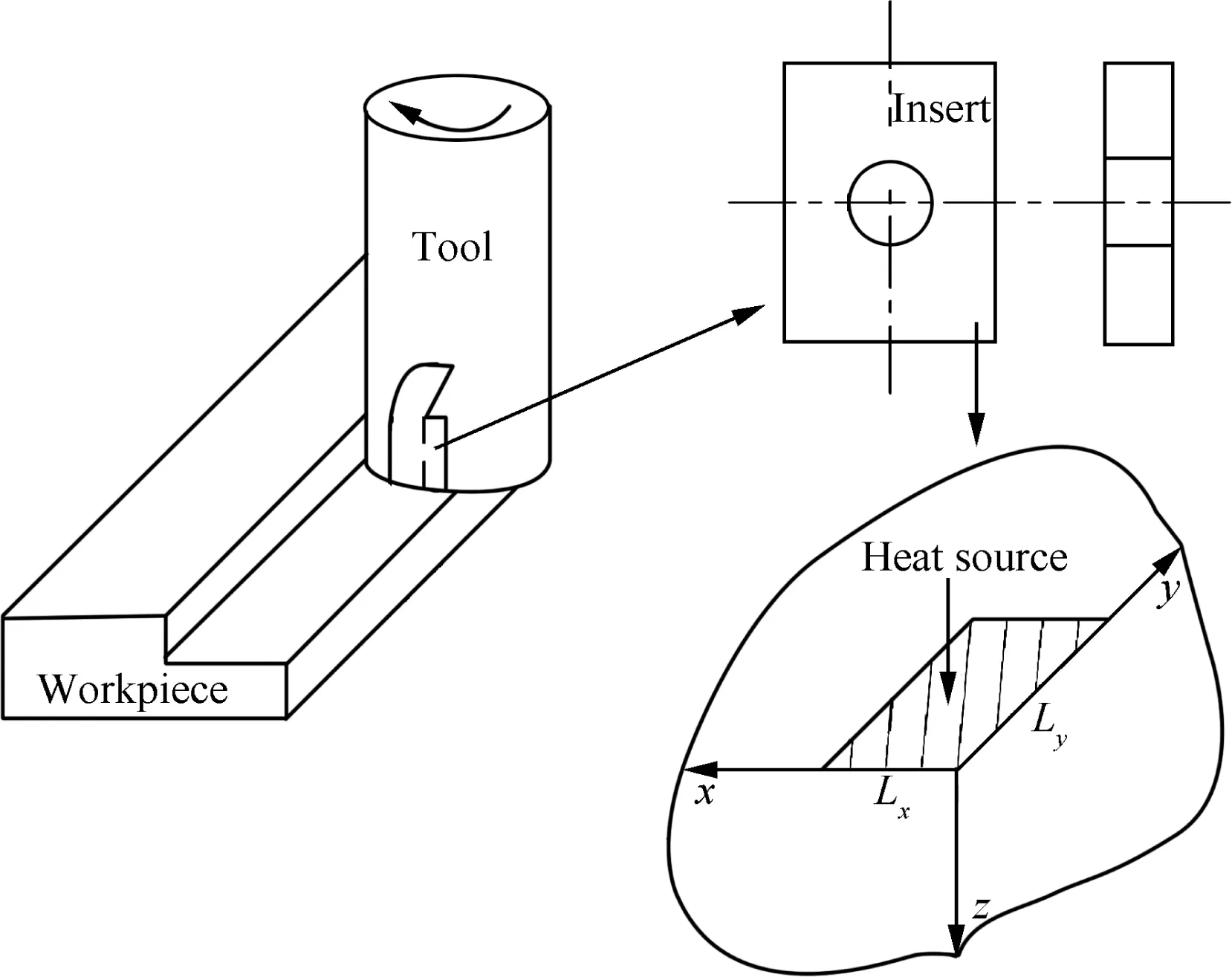
Fig.1 End milling diagram and approximation heating model.
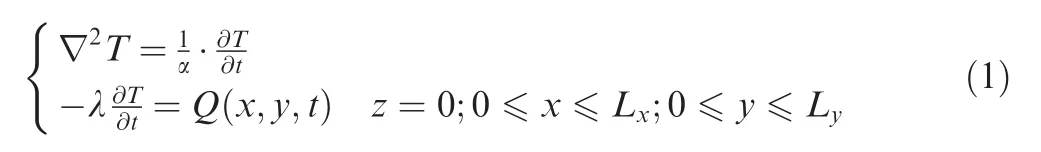
In this paper,with the heat radiation and temperature effect on the thermal properties of the tool material neglected,the governing equation and boundary condition for the temperature T of the insert are set as where α is the thermal diffusivity,t is the time,λ the thermal conductivity,Q the heat flux,and Lxand Lyare the dimensions of the heat source.Except the interface between the tool and chip,the rest surface of tool is regarded as insulated and the initial temperature is set to be 0°C.
The green function can be used to solve the above heat conduction equation.5The green function G for the temperature of a semi-infinite corner excited by an instantaneous heat source at time τ at the surface point(x=xp,y=yp,z=0)is G(x,y,z,xp,yp,0,D)
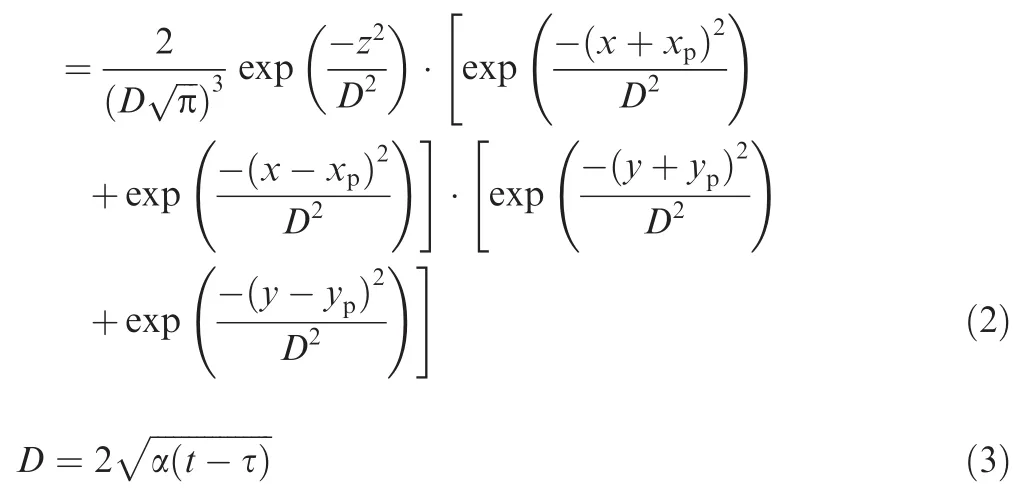
where D is a parameter with units of length,and its physical meaning is characteristic dimension for the penetration of temperature field at time t resulted from instantaneous heat source at time τ.According to Osakis’theory,18the solution of the temperature in a semi-infinite corner is
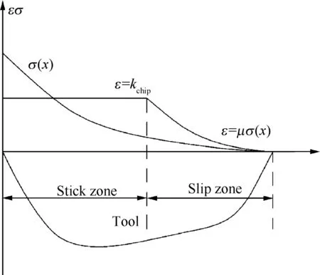
Fig.2 Stress distribution on rake face.

The magnitude of heat flux is strongly affected by the friction along the tool-chip interface.However,there are two different friction states in this interface in the process of end milling,respectively called stick zone and slip zone,as shown in Fig.2.
At the beginning of chip formation,the workpiece is squeezed from the tool and in turn forms a chip.As a result,the shear stress ε in the area that the chip closely contacts with the tool tip is constant kchip.Moreover,there is very high normal stress σ in this area.The chip is able to separate from the workpiece on the condition that the shear stress is increasingly promoted.At this moment,the shear stress matches the normal stress by the friction coefficient μ.In this study,the heat flux Q is considered to come from the uniform heat source and the liner heat source based on the following empirical equations:

where β is length ratio of stick zone over slip zone,q1(x)reflects the type of heat source distribution,and q(τ)is the source heat flux varying with time.
Eqs.(5)and(6)then will be utilized to solve the temperature equation.First,the inner double integral of the green function GR needs to be calculated:
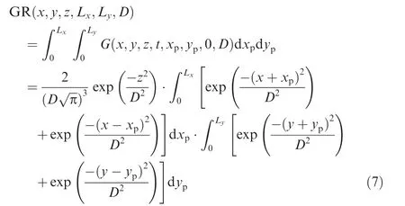
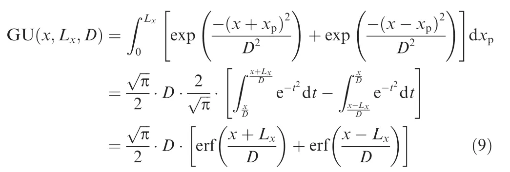
An error function erf(x)is introduced in the inner double integral calculation:

Then GU which represents the integral of variable x is calculated as
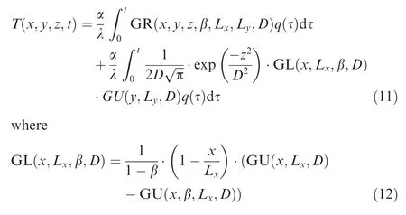
Similarly,the integral of variable y can be obtained.So the inner double integral of the green function GR is

At last,the temperature solution of the insert on the cutter is
2.2.Model of temperature dropping phase
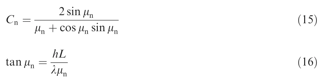
This phase refers to the time when the insert is entirely exposed in ambient air,causing its temperature to drop.The process of temperature dropping can be modeled as one of heat convection.Therefore,by approximating the insert as a thin plate with certain thickness(see Fig.3),based on the heat conduction theory,the governing equation and boundary condition for solving its temperature T can be obtained by analysis of one-dimensional thermal conduction of plate.Specifically,the following PDEs are in the following order:

where h is the convection transfer rate and Tffluid temperature.Excess temperature θ =T(L,τ)-Tfis introduced,L is the thickness of insert,the method of separation of variables then be employed to solve the problem,i.e.

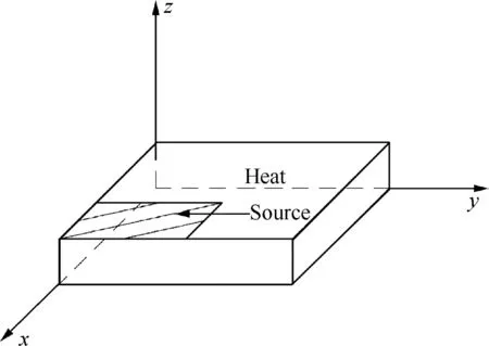
Fig.3 Insert heat convection diagram.
3.Heat flux and tool-chip contact length evaluation
Apparently,the heat flux Q and the chip-tool contact length Lxmust be obtained in order to get the tool temperature.But to measure them by experiment is too difficult to realize;as an effective alternative,the finite element simulation is fixed,while the workpiece approaches at a particularly constant speed.
3.1.Finite element model
Deformation software is employed in the simulation of the milling Inconel718 process.In the simulation,the tool is regarded as a rigid body,while the workpiece is regarded as isotropic elastic–plastic with isotropic strain-hardening.Because of high strain rate and high temperature deformation occurring in machining Inconel718,the Jason-Cook constitutive equation,which is used by many researchers,is used to describe the high strain and temperature deformation behavior,as given in Eq.(17):
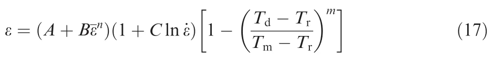
where Td,Tr,and Tmare the deformation temperature,room temperature and melt point temperature,respectively. ε,¯ε and ˙ε are shear stress,shear strain and shear strain rate,respectively.The constants A and B stand for the material yield stress and strain hardening.The mechanics characteristics of the material are represented by the stress rate sensitive coefficient C,the strain hardening exponent n and the thermal softening coefficient m.These parameters Inconel718 are listed in Table 1.19
The mesh function in the software is based on the Lagrangian-Euler techniques and adaptive re-meshing.Specifically,the mesh could be remeshed in the vicinity to form a normal mesh again after the initial mesh has become distorted.Furthermore,the mesh density in the cutting zone should be higher than that in the rest regions of the tool and workpiece.In the present study,the numbers of quadrangle elements in the insert and workpiece are 28197 and 49079 respectively.
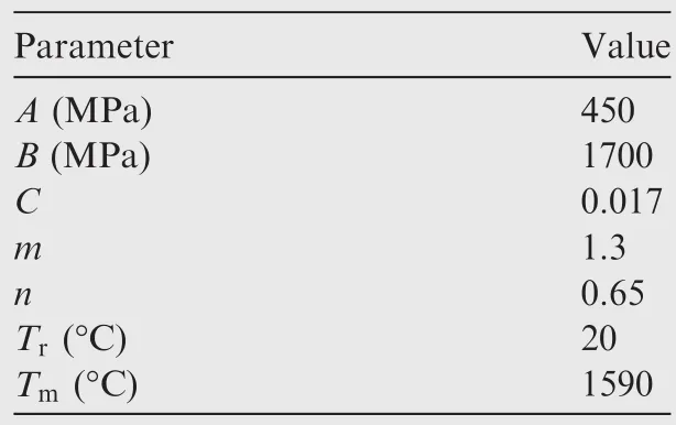
Table 1 Jason-cook constitutive of Inconel718 parameters.
The simulation is performed at ambient temperature provided that the initial temperature of the tool and workpiece is 20°C.The convection coefficient between the workpiece and air is set as 20 W/(m2·°C).According to the Coulomb law,the friction factor is taken to be 0.4.During the simulation,the insert rake angle 5°and clearance angle 5°are fixed,while the workpiece approaches at a particularly constant speed.
3.2.Chip-tool contact length Lxevaluation
The whole simulation is divided into three groups based on the cutting speed,i.e.,the cutting speed V is 60 m/min,80 m/min,and 100 m/min.At each of the three,the simulation is performed by altering feed per tooth fzin the range from 0.12 mm/z to 0.20 mm/z.The radial depth of cut aeand axial depth of cut apare set to be 4 mm and 0.5 mm respectively.The fitting formula about the relationship between Lxand fzat any particular cutting speed is obtained by the leastsquare curve fitting method.The specific results from the simulation and the fitting formulas are listed in Tables 2 and 3.
3.3.Heat flux evaluation
The same finite element method is used in the evaluation of heat flux Q.However,compared with the Lxevaluation,the coefficient of heat flux distribution γ must be taken into account in the Q evaluation,since not all heat flux generatedin the chip-tool interface can reach the tool.20Equation below provides a way to calculate it:
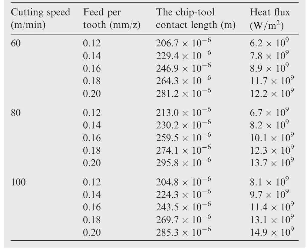
Table 2 Lxand Q obtained from simulation.
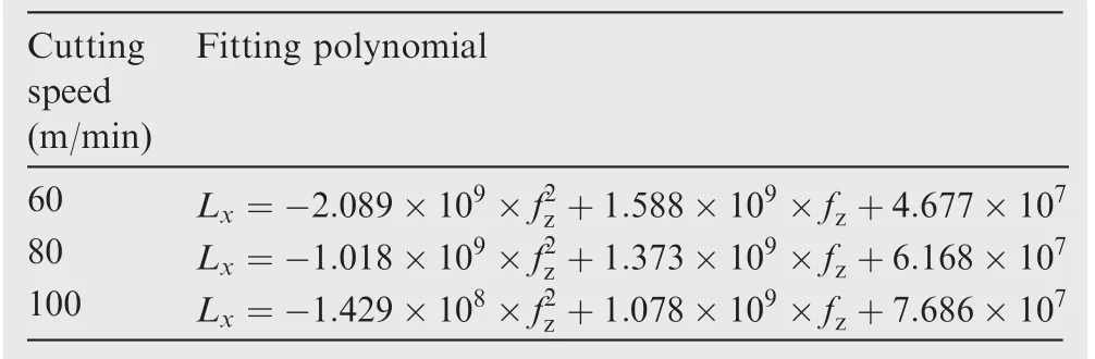
Table 3 Fitting formula of chip-tool contact length.
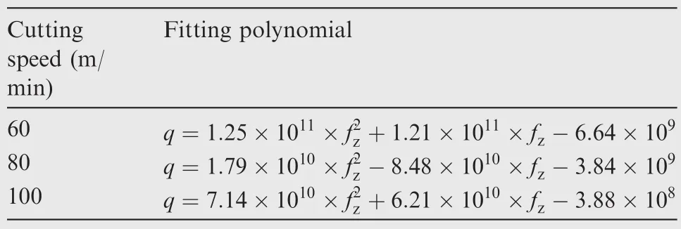
Table 4 Fitting formula of heat flux.
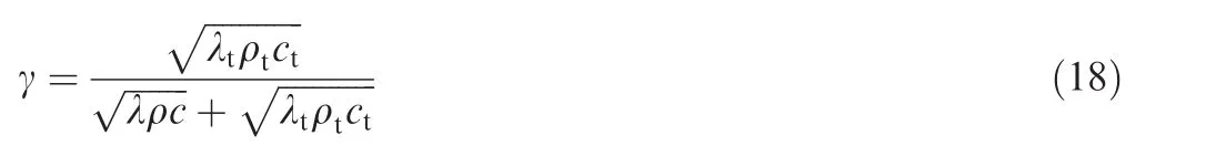
where λ,ρ and c respectively represent thermal conductivity,density,and specific heat,with the subscript t indicating whether the particular coefficient is for the tool(with t)or the workpiece(without t).The specific results of the heat flux Q and the fitting formulas are listed in Table 4.
4.Experiments
To verify the established temperature model,a physical milling experiment is carried out.It is performed at a four-axis machine center,as shown in Fig.4.The workpiece material is Inconel718,which is extensively used in aeroengines.A double-tooth end milling cutter with a carbide insert is selected in this experiment and its specific parameters are shown in Table 5.
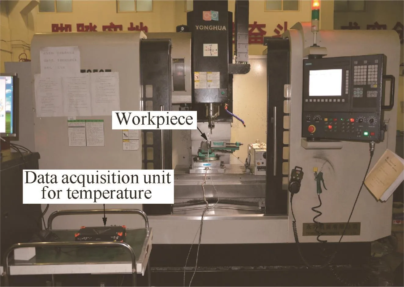
Fig.4 Temperature measuring experiment.
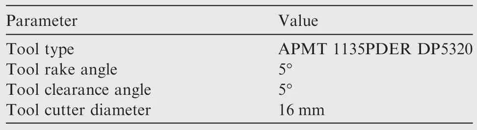
Table 5 Tool parameters.
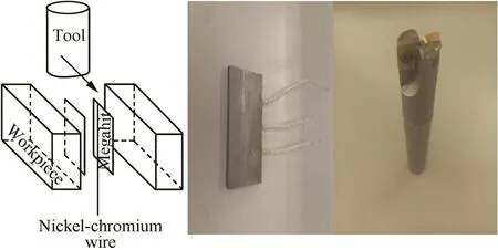
Fig.5 Single wire thermocouple and tool.
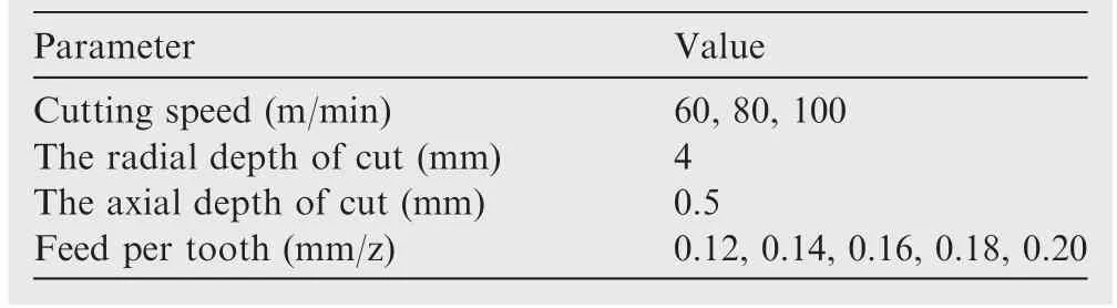
Table 6 Critical cutting parameters.
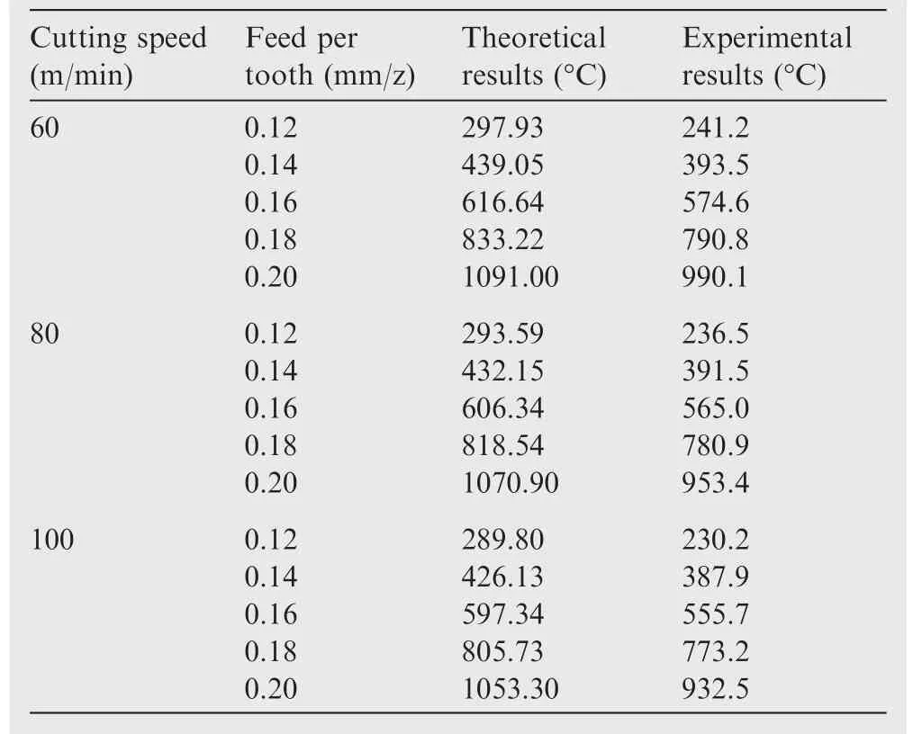
Table 7 Theoretical and experimental results.
Single wire thermocouple is used in the milling experiment to measure the temperature.First,the workpiece is divided into two parts across the line of milling direction.Next,two pieces of megahit,as insulted conductor,are introduced between the two parts.Besides,a nickel–chromium wire is employed as thermocouple and located in between them.Finally,the three components mentioned above are combined as a whole sample by binder,as shown in Fig.5.In the process of milling experiment,the insulted conductor is destroyed by the milling action,which makes the nickel–chromium wire exposed and contact with the workpiece.When the tool is approaching,the temperature signal is produced.
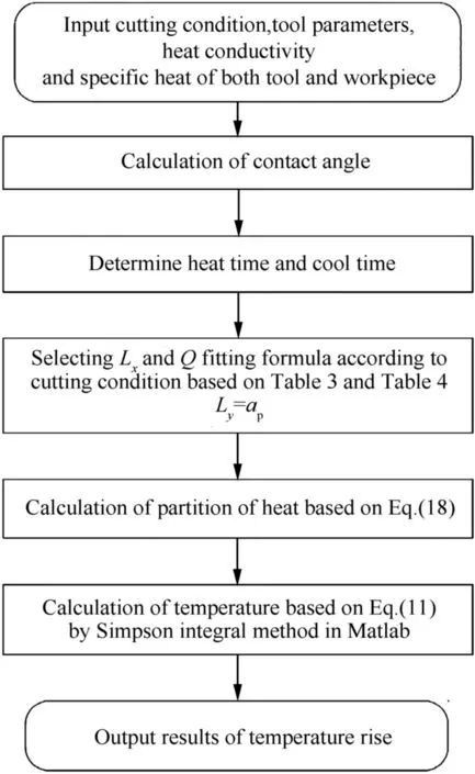
Fig.6 Flowchart for temperature rise calculation.
Those cutting parameters,such as cutting speed,axial depth of cut,radial depth of cut,and feed per tooth,do affect the temperature.However,the cutting speed,and feed per tooth are more crucial and are considered to be dominating ones in insert wear.So the focus of our milling experiment is placed on these two parameters and their ranges are chosen in accordance with the optimal values from the SANDVIK recommendation,as listed in Table 6.The rest of parameters are simply set to be some constants,e.g.,the axial depth of cut is set to be 0.5 mm,and the radial depth of cut is set to be 4 mm.
5.Results and discussion
Table 7 shows the theoretical results calculated by our tool prediction model as the process shown in Fig.6 and the experimental results measured by single wire thermocouple under different cutting conditions with a fixed radial depth of cut and axial depth of cut.
The trends of both theoretical and experimental results in temperature change are verified to be in good agreement.However,the experimental results tend to be lower than the theoretical calculated ones.The reason behind this deviation may be conjectured from the following aspects.First,the coated layer which can prevent heat from entering the tool has not been taken into account in the theoretical model.Secondly,the cutting speed in our experiment belongs to high speed milling for Inconel718.So,compared to conventional milling,there may not be enough heat conducting into the tool during the short contact time.Thirdly,the analysis assumption that the tool is regarded as a rectangular corner ignores the toolrakeangle,which may howeveraffectthetool temperature.
The temperature change has an inverse trend against the cutting speed.This is partly because that the increase of cutting speed may reduce the heating time of the cutter during the machining process.The temperature is also found to increase with the per tooth feed;this agrees with the common knowledge that,with the increase of the per tooth feed,there will be more material to be removed in a cutting cycle and hence more energy is consumed and converted into heat.
6.Conclusions
(1)A new analytical model for predicting the cutting tool temperature in end milling is presented in this paper with consideration of real friction state on the tool-chip interface and the temperature dropping phase.
(2)With different cutting parameters,both computer simulation using the proposed analytical model and physical cutting experiment are carried out,and the two results show good agreement.
(3)The experimental results suggest that the tool temperature increases with the feed per tooth but decreases with the cutting speed.The proposed theoretical model for cutting tool temperature prediction can be further enhanced and then used to optimize the cutting condition to prevent excessive tool wear in end milling.
Acknowledgments
This work was supported by the National Basic Research Program of China(No.2013CB035802)and National Natural Science Foundation of China(No.51475382).
1.Abukhshim NA,Mativenga PT,Sheikh MA.Heat generation and temperature prediction in metal cutting:a review and implication for high speed machining.Int J Mach Tools Manuf 2006;46(7–8):782–800.
2.Young HT.Cutting temperature responses to flank wear.Wear 1996;201(1–2):117–20.
3.Pradip M,Jayaramachandran R,Ganesan S.Finite element analysis of temperature rise in metal cutting process.Appl Therm Eng 2005;25(14–5):2152–68.
4.Radulescu R,Kapoor SG.An analytical model for prediction of tool temperature fields during continuous and interrupted cutting.J Eng Ind 1994;116(2):135–43.
5.Stephenson DA,Ali A.Tool temperatures in interrupted metal cutting.J Eng Ind 1992;114(2):127–36.
6.Lin J.Inverse estimation of the tool-work interface temperature in end milling.Int J Mach Tools Manuf 1995;35(5):751–60.
7.Ueda T,Hosokawa A,Oda K,Yamada K.Temperature on flank face of cutting tool in high speed milling.CIRP Ann–Manuf Technol 2001;50(1):37–40.
8.Lazoglu I,Altintas Y.Prediction of tool and chip temperature in continuous and interrupted machining.Int J Mach Tools Manuf 2002;42(9):1011–22.
9.Sato M,Ueda T,Tanaka H.An experimental technique for the measurement of temperature CBN tool face in end milling.Int J Mach Tools Manuf 2007;47(14):2071–6.
10.Sato M,Tamura N,Tanaka H.Temperature variation in the cutting tool in end milling.J Manuf Sci Eng 2011;133(2):1–7.
11.Coz GL,Marinescu M,Devillez A,Dudzinski D,Velnom L.Measuring temperature of rotating cutting tools:application to MQL drilling and dry milling of aerospace alloys.Appl Therm Eng 2012;36(4):434–41.
12.Jen TC,Eapen S,Gutierrez G.Nonlinear numerical analysis in transient cutting tool temperatures.J Manuf Sci Eng 2003;125(1):48–56.
13.Yang Y,Zhu WW.Study on cutting temperature during milling of titanium alloy based on FEM and experiment.Int J Adv Manuf Technol 2014;73(9):1511–21.
14.Jen TC,Aloysius U,Anagonye AU.An improved transient model of tool temperatures in metal cutting.J Manuf Sci Eng 2001;123(1):30–7.
15.Feng Y,Zheng L,Wang ML,Wang BS,Hou J,Yuan TJ.Research on cutting temperature of work-piece in milling process based on WPSO.Int J Adv Manuf Technol 2015;79(1):427–35.
16.Cui XB,Zhao J,Pei ZQ.Analysis of transient average tool temperatures in face milling.Int Commun Heat Mass Transfer 2012;39(6):786–91.
17.Chen M,Sun FH,Wang HL,Yuan RW,Qu ZH,Zhang SQ.Experimental research on the dynamic characteristics of the cutting temperature in the process of high-speed milling.J Mater Process Technol 2003;138(1–3):468–71.
18.Ozisik MN.Heat conduction.3rd ed.New York:Wiley;1980.p.300–44.
19.Uhlmann E,Graf von der Schulenburg M,Zettier R.Finite element modeling and cutting simulation of Inconel718.CIRP Ann– Manuf Technol 2007;56(1):61–4.
20.Sekhon GS,Chenot JL.Numerical simulation of continuous chip formation during non-steady orthogonal cutting.Eng Comput 1993;10(1):31–48.
Wu Baohai received the B.S.,M.S.and Ph.D.degrees from Xi’an Jiaotong University in 1997,2000,and 2005,respectively,and is now an associate professor there.His main research interests are multi-axis machining and intelligent machining.
Cui Di received the B.S.and M.S.degrees from Xi’an Technological University,Northwestern Polytechnical University in 2011 and 2015,respectively,and is now a Ph.D.candidate there.His main research interests are multi-axis machining and intelligent machining.
16 November 2015;revised 4 January 2016;accepted 11 January 2016
Available online 21 October 2016
Analytical model;
Cutting tool;
End milling;
Temperature prediction;Tool temperature
Ⓒ2016 Chinese Society of Aeronautics and Astronautics.Production and hosting by Elsevier Ltd.This is anopenaccessarticleundertheCCBY-NC-NDlicense(http://creativecommons.org/licenses/by-nc-nd/4.0/).
*Corresponding author.
E-mail address:dhzhang@nwpu.edu.cn(Z.Dinghua).
Peer review under responsibility of Editorial Committee of CJA.
Production and hosting by Elsevier
http://dx.doi.org/10.1016/j.cja.2016.03.011
1000-9361Ⓒ2016 Chinese Society of Aeronautics and Astronautics.Production and hosting by Elsevier Ltd.
This is an open access article under the CC BY-NC-ND license(http://creativecommons.org/licenses/by-nc-nd/4.0/).
杂志排行

CHINESE JOURNAL OF AERONAUTICS的其它文章
- Analysis of swirling flow eff ects on the characteristics of unsteady hot-streak migration
- Implicit discontinuous Galerkin method on agglomerated high-order grids for 3D simulations
- Design and implementation of rigid-flexible coupling for a half-flexible single jack nozzle
- Dynamic simulation of aerial towed decoy system based on tension recurrence algorithm
- A quasi-one-dimensional model for hypersonic reactive flow along the stagnation streamline
- An experimental investigation on static directional stability