Flow regime and head loss in a drip emitter equipped with a labyrinth channel*
2016-10-18LinZHANG张林PuteWU吴普特DelanZHU朱德兰ChaoZHENG郑超
Lin ZHANG (张林), Pu-te WU (吴普特), De-lan ZHU (朱德兰), Chao ZHENG (郑超)
1. Institute of Soil and Water Conservation, Northwest A&F University, Yangling 712100, China,
E-mail: zl0211wy@163.com
2. College of Water Resources and Architectural Engineering, Northwest A&F University, Yangling 712100,China
Flow regime and head loss in a drip emitter equipped with a labyrinth channel*
Lin ZHANG (张林)1, Pu-te WU (吴普特)1, De-lan ZHU (朱德兰)2, Chao ZHENG (郑超)1
1. Institute of Soil and Water Conservation, Northwest A&F University, Yangling 712100, China,
E-mail: zl0211wy@163.com
2. College of Water Resources and Architectural Engineering, Northwest A&F University, Yangling 712100,China
Labyrinth channels are widely adopted in emitter designs to regulate the water flow. The flow regime and the head loss of labyrinth channels have significant impacts on the hydraulic performance of emitters. In this study, the flow behavior of water passing through an emitter channel is observed using the micro particle image velocimetry (PIV), and the head loss during the flow is analyzed for an emitter with a triangular labyrinth channel. The results show that the flow regime is consistent with the classical theory of hydraulics governing straight channels, even when the cross-sectional area is very small (as small as 0.5 mm×0.5 mm). The critical Reynolds number from laminar to turbulent flows in a labyrinth channel is approximately in a range between 43 and 94. The local head loss factor decreases as the Reynolds number increases for labyrinth channels with smaller cross-sectional areas, such as 0.5 mm×0.5 mm and 1.0 mm×1.0 mm. The local head loss factor is not related to the Reynolds number and is only a function of the boundary conditions of the labyrinth channel when the Reynolds number exceeds approximately 1 000 (for cross-sectional areas of 1.5 mm×1.5 mm and 2.0 mm×2.0 mm). The ratio of the local head loss to the total head lossfirst increases and then remains nearly constant as the Reynolds number increases in the labyrinth channel. The head loss in the labyrinth channel is almost equal to the local head loss, and)is approximately 0.95 for cross-sectional areas of greater than 1.0 mm×1.0 mm. These results can be used for optimizing the design of emitter channels.
emitter, flow regime, labyrinth channel, head loss
Introduction
Emitters are key components of drip irrigation systems[1-3]. To allow the pressurized water in pipes to drip slowly into the soil, most emitter channels are small and in a complex structure[4,5]. The cross-sectional area of the channel is generally less than 1 mm2,and a labyrinth structure is widely adopted to enable the emitter channel to regulate the water flow[6-9]. Mattar and Al-Amoud[10]indicated that the pressure loss during the flow is caused by the tortuous route of the emitter channel. With the small size and the complex structure of the emitter channel, it is impossible to observe the flow behavior of the water passingthrough an emitter channel before the micro particle image velocimetry (PIV) technology is developed. Many simulations were conducted for the emitter channel flow[11-13]. Wu et al.[14]used the standard k-ε model and the large eddy simulation (LES) method to analyze the flow characteristic in the drip irrigation emitter, and the results showed that the LES model was more effective to simulate the flow characteristics in the flow path of drip irrigation emitters. Under the condition of the turbulent flow in labyrinth channels,Wei et al.[15]calculated the distributions of the pressure and the velocity and the relationship between the pressure and the discharge rate for channels with three different shapes (triangular, rectangular, and trapezoidal) using the CFD method. Moreover, the results of the labyrinth channel simulation are well consistent with the experimental data. The CFD provides a promising tool for the design of emitter channels with fewer experimental channels and laboratory experiments.
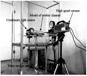
Fig.1 Experimental setup
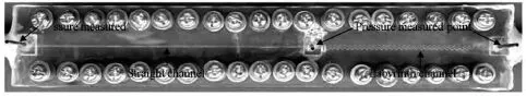
Fig.2 The emitter channel model used for testing
According to the traditional hydrodynamics, the flow through labyrinth channels is typically laminar at the flow rates and the path dimensions for drip emitters. Nevertheless, some studies did show that the flow in labyrinth channels might be turbulent[16-19]. Thus, the question arises, “which type of flow model,the turbulent flow or the laminar flow, should be adopted in the CFD simulations for emitters with labyrinth channels”. To answer this question, the flow behavior of water passing through an emitter channel is observed using the micro PIV and the head loss is analyzed during the flow for a triangular emitter labyrinth channel. The head loss includes the friction head loss and the local head loss. The friction head loss is the loss of energy that occurs in the flow due to the viscous effects generated by the surface of the emitter channel. The local head loss mainly occurs at the entrance and a single bend in the emitter channel. The results prove very valuable for optimizing the design of emitter channels.
1. Materials and methods
1.1 Experimental design
The experiments on the flow regime and the head loss of a drip emitter equipped with a labyrinth channel are conducted at the Irrigation Hydraulics Laboratory(IHL), Northwest A&F University, Yangling, China. The testing apparatus consists of a 90-l cylindrical stainless steel water storage tank, a vortex pump driven by an electric motor, the PVC pipe, valves, a model of an emitter channel, several pressure transducers, a plastic cup, a micro PIV instrument and other necessary equipment. The experimental setup is shown in Fig.1.
A model of an emitter channel is fabricated using two pieces of plexiglass. The emitter channel is carved on one piece, and the second piece is used to cover the first one. The two pieces of plexiglass are then fastened using 38 bolts to form a closed emitter channel. The emitter channel consists of a straight channel and a triangular labyrinth channel, both of square cross section, as shown in Fig.2. The length of the straight channel and the flow length of the labyrinth channel are both 16 cm. Four different square cross sectional areas are used in the emitter channels: 0.5 mm× 0.5 mm, 1.0 mm×1.0 mm, 1.5 mm×1.5 mm and 2.0 mm×2.0 mm, respectively. Each emitter channel model is tested at 5 kPa and 10 kPa and from 20 kPa to 360 kPa with an increment of 20 kPa.
Xi'an Xinming model CYB13 pressure transducers are installed at the inlet of the straight channel,the inlet of the labyrinth channel, and at the outlet of the labyrinth channel, for measuring pressures from 0 kPa to 400 kPa at ±0.1%accuracy. The transducers are calibrated at the IHL before the start of the experiments, and all three transducers are connected to a data logger, which is used to record the pressure at an interval of 5 s during each emitter test of 15 min. The average pressures at the inlet of the straight channel, the inlet of the labyrinth channel and the outlet of the labyrinth channel are calculated in each test. Then, the friction head loss for the straight channel and the total head loss for the labyrinth channel are calculated using the pressures measured at the inlet of the straight channel, the inlet of the labyrinth channel and the outlet of the labyrinth channel. Because the length of the straight channel and the length along the flow of the labyrinth channel are the same, the friction head loss for the labyrinth channel is equivalent to the friction head loss for the straight channel in each test. Therefore, the local head loss for the labyrinth channel is also calculated using the total and friction head losses for each test. The water exiting the emitter channel is collected in a plastic cup,and the weight of the water is measured using an ele-ctronic balance (Shuangjie, model JJ2000, accuracy,0.1 g). The temperature of the water in the plastic cup is measured using a thermometer with an accuracy of 0.1oC, and the corresponding change of the water viscosity is calculated for each test.
The micro PIV measurement system consists of a continuum light source, a high-speed camera and a magnifier (VS-M0910). The high-speed camera is model HotShot 512 of NAC Image Technology, used to record the brilliant color, with resolutions up to 512×512 pixels, and a maximum of 200 000 fps can be captured. With the onboard memory of up to 16GB,the HotShot 512 provides an ultra-long recording time-over 10 min at the full resolution with reduced frame rates. The particle movement in the emitter channel is clearly observed using the micro PIV, and the particle velocity is calculated using the software Movias Pro Viewer 1.63, based on the distance traveled by the particles. Hollow glass beads are added to the water storage tank (0.0001 kg of beads per liter of water) for better observing the flow behavior of water passing through the emitter channel, these beads are used because their density (1 100 kg/m3) is similar to that of water. Hollow glass beads with diameters in the range from 19 µm to 21 µm are selected using 650- and 800-mesh sieves.
1.2 Calculations of friction head loss factor and local
head loss factor
The Darcy-Weisbach equation can be used to determine the friction head loss in a circular pipe as follows[20]

where hfis the friction head loss,fis the friction head loss factor,l is the length of the pipe,Ris the hydraulic radius,Vis the velocity andgis the ratio of weight to mass.
The friction head loss factor can be determined using Eq.(1) as
The friction head loss in the straight channel is measured directly, and the velocity is calculated based on the flow rate and the cross-sectional area of the straight channel in each test. Substituting the values of the friction head loss and the velocity obtained into Eq.(2), the friction head loss factor is calculated for each test.
The total head loss for the labyrinth channel is measured using two pressure transducers. Because the length of the straight channel and the length along the flow of the labyrinth channel are the same, the friction head loss for the labyrinth channel is equivalent to the friction head loss for the straight channel in each test. The friction head loss for the straight channel is also measured using two pressure transducers. Therefore,the local head loss for the labyrinth channel can be calculated from the total and friction head losses for each test. According to the classical hydraulics theory,the local head loss can be calculated from the following equation[20]
where hjis the local head loss andεis the local head loss factor.
The local head loss factor can be determined as

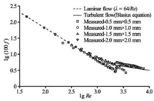
Fig.3 The relationship between friction loss factor and Reynolds number

Fig.4 The particle movement trajectories at different Reynolds numbers(Re)in a straight channel with a cross-sectional area of 1.0 mm×1.0 mm
The Reynolds number is defined as the ratio of the inertial forces to the viscous forces and is used to characterize different flow regimes within a similar fluid, such as laminar or turbulent flow. It can be calculated as
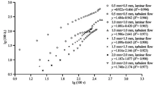
Fig.5 The relationship between friction head loss and water velocity

whereRe is the Reynolds number,Ris the hydraulic radius,γis the kinematic viscosity.
2. Results and discussions
2.1 The flow regime and friction head loss in the straight channel
The relationship between the friction head loss factor and the Reynolds number is shown in Fig.3 for straight channels with different cross-sectional areas. As shown in Fig.3, the flow is laminar when the Reynolds number is less than 2 000, and the flow becomes turbulent when the Reynolds number exceeds 2 000. The measured values are very close to the estimated values of the friction head loss factor, regardless of whether the flow is laminar or turbulent in the straight channel.
The movement of the hollow glass beads in the water in the straight channel is observed using the micro PIV measurement system. During the same period, three hollow glass beads are selected randomly,the movement trajectories of these beads are shown in Fig.4 (with Reynolds numbers of 1 930 and 2 216 for the straight channel with a cross sectional area of 1.0 mm×1.0 mm). As shown in Fig.4, the movement trajectories of the three hollow glass beads ran parallel to the border of the straight channel at a Reynolds number of 1 930, indicating that the flow is laminar. The movement trajectories of the three hollow glass beads are curved and cut cross each other, indicating that the flow becomes turbulent at a Reynolds number of 2 216. Therefore, we can conclude that the critical Reynolds number at which the flow changes from laminar to turbulent is approximately 2 000 in the straight channel. The movement trajectories of the particles provide further evidence that the flow regime is consistent with the classical hydraulics theory, even though the cross-sectional area of the straight channel is as small as 0.5 mm×0.5 mm.

Fig.6 Particle trajectories at a Reynolds number of 43
Figure 5 shows the relationship between the friction head loss and the water flow velocity for straight channels with various cross-sectional areas. The results are consistent with those predicted by the classical hydraulics theory. The friction head loss is roughly proportional to the water velocity for laminar flow and for turbulent flow, but for the latter the curve is 1.5 and 2.0 times steeper than for the former.
2.2 The flow regime and local head loss in the labyrinth channel
Two hollow glass beads are selected randomly during the same period. In Fig.6, the movement trajectories of these beads in the second and third units at the inlet and in the second and third units at the outlet of the labyrinth channel are shown, where the crosssectional area is 0.5 mm×0.5 mm and the Reynolds number is 43. As shown in Fig.6, the movement trajectories of the two hollow glass beads run almost parallel to the border of the labyrinth channel at a Reynolds number of 43. The hollow glass beads move along a straight line in the straight segment of the labyrinth channel. The direction of movement of the hollow glass beads is changed by the centrifugal force at the tooth angle of the labyrinth channel, but the beads continue to move along a straight line after the tooth angle because the viscous force is larger than the inertial force at low Reynolds numbers. Although the movements of the hollow glass beads are disturbed continually by the tooth angles until they move out of the labyrinth channel, as shown in Fig.6(b), the movement trajectories of the hollow glass beads at the outlet of the labyrinth channel remain similar to those at the inlet of channel. Therefore, the flow tends to be laminar in the labyrinth channel at a Reynolds number of 43.
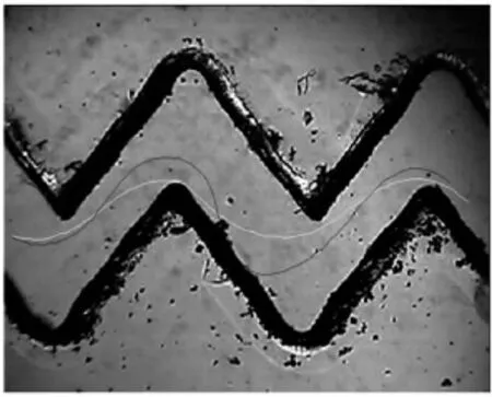
Fig.7 Particle trajectory at the Reynolds number of 94
Figure 7 shows the particle trajectory in the second and third units at the inlet of the labyrinth channel with a cross-sectional area of 0.5 mm×0.5 mm, where the Reynolds number is 94. As shown in Fig.7, the movement trajectories of the two observed hollow glass beads are more disordered than those observed at the Reynolds number of 43, this is because the inertial force becomes increasingly larger than the viscous force as the Reynolds number increases. Based on these experiments, we conclude that the critical Reynolds number at which the flow changes from laminar to turbulent in the labyrinth channel is approximately in the range between 43 and 94.

Fig.8 The relationship between local loss factor and Reynolds number

Fig.9 Particle trajectory at a Reynolds number of 317 in a labyrinth channel with a cross-sectional area of 1.5 mm× 1.5 mm
Figure 8 shows the relationship between the local head loss factor and the Reynolds number for different cross-sectional areas. The local head loss factor decreases as the Reynolds number increases for smaller cross-sectional areas, such as 0.5 mm×0.5 mm and 1.0 mm×1.0 mm. The local head loss factor increases at first and then remains nearly constant as the Reynolds number increases at larger cross-sectional areas (for example, 1.5 mm×1.5 mm and 2.0 mm× 2.0 mm). The local head loss factor is not related to the Reynolds number and is only a function of the boundary conditions of the labyrinth channel when the Reynolds number exceeds approximately 1 000. The reason for the difference in the relationship between the local head loss factor and the Reynolds numberbetween smaller and larger cross-sectional areas is(Fig.9) that a straight main flow region can be formed between two rows of teeth tines, and vortex regions can occur between adjacent teeth tines in the same row due to the degree of occlusion between two opposite and adjacent teeth tines, which is not enough in a large labyrinth channel, i.e., 1.5 mm×1.5 mm. Most particles can move through the straight main flow region, unlike in the smaller labyrinth channels, i.e.,with dimensions of 0.5 mm×0.5 mm and 1.0 mm× 1.0 mm. The main flow region remains labyrinthine because the degree of occlusion between two opposite and adjacent teeth tines is sufficient in smaller labyrinth channels. Most particles pass from the main flow region of the labyrinth in a smaller labyrinth channel,and this is why the relationship between the local head loss factor and the Reynolds number differs between smaller and larger labyrinth channels. Additionally,the local head loss factor for a cross-sectional area of 2.0 mm×2.0 mm is smaller than that for a cross-sectional area of 1.5 mm×1.5 mm with the same Reynolds number. Because the main flow regions in labyrinth channels with cross-sectional areas of 2.0 mm× 2.0 mm and 1.5 mm×1.5 mm are both straight, the cross-sectional area is larger, and the effect of tooth tine on the water movement is smaller.
The relationship between the local head loss and the water velocity is shown in Fig.10. As shown in Fig.10, the local head loss increases as the water velocity increases. The local head loss is proportional to the water velocity with a slope of approximately 1.6 for labyrinth channels with cross-sectional areas of 0.5 mm×0.5 mm and 1.0 mm×1.0 mm and with a slope of approximately 2.0 for labyrinth channels with cross-sectional areas of 1.5 mm×1.5 mm and 2.0 mm× 2.0 mm.

Fig.10 The relationship between local head loss and water velocity
2.3 The ratio of local head loss to total head loss in the labyrinth channel
Labyrinth channels exhibit the advantage of a positive energy dissipation effect; thus, labyrinth channels are commonly used in emitters to regulate the water flow and allow the pressurized water in pipes to drip slowly into soil. Thus, it is important to study the ratio of the local head loss to the total head lossfor emitters with labyrinth channel designs. The value ofin labyrinth channels is shown in Fig.11. As shown in Fig.11,increases as the Reynolds number increases. However, when the Reynolds number increases to a value greater than a certain value,remains nearly constant. When the Reynolds number exceeds approximately 2 000,remains at approximately 0.95 for channels with cross-sectional areas of 1.0 mm×1.0 mm,1.5 mm×1.5 mm and 2.0 mm×2.0 mm. The head loss in labyrinth channels is almost entirely due to the local head loss, and the friction head loss can be neglected for cross-sectional areas of greater than 1.0 mm×1.0 mm. When the Reynolds number exceeds approximately 1 000,remains approximately 0.82 for a cross-sectional area of 0.5 mm×0.5 mm. The abovementioned value ofis smaller than the value offor other cross-sectional areas because for smaller cross-sectional areas, the impact of the viscous force on the water movement is greater,and the ratio of the friction head loss to the total head loss in labyrinth channels is larger. Therefore, in emitter designs, it is recommended that the cross-sectional area of the labyrinth channel should be larger than 1.0 mm×1.0 mm. If the cross-sectional area is too small (i.e., 0.5 mm×0.5 mm or less), then the energy dissipation will not exceed that of channels with larger cross-sectional areas and the channel may become clogged easily due to the small channel size.

Fig.11 The ratio of local head loss to total head loss
3. Summary and conclusions
(1) The critical Reynolds number at which the flow changes from laminar to turbulent is approximately 2 000 in straight channels. The friction head loss is roughly proportional to the water velocity for laminar flow and for turbulent flow in straight channels,but for the latter it is with a slope of approximately 1.5to 2.0 times of that for the former. The flow regime is consistent with the classical hydraulics theory, even for straight channels with very small cross-sectional areas (0.5 mm×0.5 mm).
(2) The critical Reynolds number at which the flow changes from laminar to turbulent in labyrinth channels is approximately in the range between 43 and 94. The local loss factor decreases as the Reynolds number increases for labyrinth channels with smaller cross-sectional areas, such as 0.5 mm×0.5 mm and 1.0 mm×1.0 mm. The local head loss factor is not correlated with the Reynolds number and is only a function of the boundary conditions of the labyrinth channel when the Reynolds number exceeds approximately 1 000 for labyrinth channels with cross-sectional areas of 1.5 mm×1.5 mm and 2.0 mm×2.0 mm.
(3) The ratio of the local head loss to the total head loss increases at first and then remains nearly constant as the Reynolds number increases in labyrinth channels. The head loss in labyrinth channels is almost equal to the local head loss, and the ratio of the local head loss to the total head loss is approximately 0.95 for the cross-sectional areas of greater than 1.0 mm×1.0 mm.
Acknowledgements
This work was supported by the West Light Foudation of the Chinese Academy of Sciences, the Basic Scientific Research Business Special Fund Projects,Northwest A&F University (Grant No. 2014YB061).
References
[1] WEI Zheng-ying, ZHAO Wan-hua and TANG Yi-ping et al. Anti-clogging design method for the labyrinth path of drip irrigation emitters[J]. Transactions of the Chinese Society of Agricultural Engineering, 2005, 21(6): 1-7(in Chinese).
[2] YANG Pei-ling, LEI Xian-long. Development and research of drip irrigation emitters[J].Water Saving Irrigation,2000, (3): 17-19 (in Chinese).
[3] WANG Fang, WU Pu-te and FAN Xing-ke . Numerical simulation and frame designing of emitter's labyrinth channel[J]. Journal of Irrigation and Drainage, 2007,26(3): 34-38(in Chinese).
[4] NIU W., LIU L. and CHEN X. Influence of fine particle size and concentration on the clogging of labyrinth emitters[J]. Irrigation Science, 2013, 31(4): 545-555.
[5] ZHANG J., ZHAO W. H. and LU B. H. New method of hydraulic performance evaluation on emitters with labyrinth channels[J]. Journal of Irrigation and Drainage Engineering, 2011, 137(12): 811-815.
[6] QIU Xiang, LUO Jian-ping and HUANG Yong-xiang et al. Scale analysis of turbulent channel flow with varying pressure gradient[J]. Journal of Hydrodynamics, 2014,26(1): 129-136.
[7] LIU Hai-sheng, LI Yun-kai. Flow characteristics in energy dissipation units of labyrinth path in the drip irrigation emitters with DPIV technology[J]. Journal of Hydrodynamics, 2009, 21(6): 137-145.
[8] ZHANG J., ZHAO W. and TANG Y. et al. Numerical investigation of the clogging mechanism in labyrinth channel of the emitter[J]. International Journal for Numerical Methods in Engineering, 2007, 70(13): 1598-1612.
[9] LI Yong-xin, LI Guang-yong and QIU Xiang-yu et al. Modeling of hydraulic characteristics through labyrinth emitter in drip irrigation using computational fluid dynamics[J]. Transactions of the Chinese Society of Agricultural Engineering, 2005, 21(3): 12-16(in Chinese).
[10]MATTAR M. A., AL-AMOUD A. I. Artificial neural networks for estimating the hydraulic performance of labyrinth-channel emitters[J]. Computers and Electronics in Agriculture, 2015, 114: 189-201.
[11] XU Ming, HU Guo-liang and ZOU Jun et al. Dynamic behavior study of the cavitation bubble in the tube[J]. Chinese Journal of Hydrodynamics, 2014, 29(4): 385-392(in Chinese).
[12] WANG Shang-jin, LIU Xiao-min and XI Guang et al. Flow characteristics in labyrinth emitter used for agricultural irrigation[J]. Transactions of the Chinese Society of Agricultural Engineering, 2000, 16(4): 61-63(in Chinese).
[13] LI Y., YANG P. and XU T. et al. CFD and digital particle tracking to assess flow characteristics in the labyrinth flow path of a drip irrigation emitter[J]. Irrigation Science,2008, 26(5): 427-438.
[14] WU D., LI Y. K. and LIU H. S. et al. Simulation of the flow characteristics of a drip irrigation emitter with large eddy methods[J]. Mathematical and Computer Modeling, 2013, 58(3-4): 497-506.
[15] WEI Q., SHI Y. and DONG W. Study on hydraulic performance of drip emitters by computational fluid dynamics[J]. Agricultural Water Management, 2006, 84(1-2): 130-136.
[16] AL-AMOUD A. I., MATTAR M. A. and ATEIA M. I. Impact of water temperature and structural parameters on the hydraulic labyrinth-channel emitter performance[J]. Spanish Journal of Agricultural Research, 2014, 12(3): 580-593.
[17] ZHANG J., ZHAO W. and TANG Y. et al. Structural optimization of labyrinth-channel emitters based on hydraulic and anti-clogging performances[J]. Irrigation Science,2011, 29(5): 351-357.
[18] KANDILIKAR S. G., JOSHI S. and TIAN S. Effect of surface roughness on heat transfer and fluid flow character at low Reynolds numbers in small diameter tubes[J]. Heat Transfer Engineering, 2003, 24(3): 4-16.
[19] WEI Q., SHI Y. and LU G. et al. Study of hydraulic performance of the eddy channel for drip emitters[J]. Irrigation and Drainage, 2006, 55(1): 61-72.
[20] WU Chi-gong. Hydraulics[M]. Fourth Edition, Beijing: Higher Education Press, 2008(in Chinese).
10.1016/S1001-6058(16)60665-0
October 28, 2014, Revised January 14, 2015)
* Project supported by the National Natural Science Foundation of China (Grant No. 51409244), the National Science and Technology Support Program (Grant No. 2015BAD22B01-02).
Biography: Lin ZHANG (1981-), Male, Ph. D.,
Associate Research Fellow
2016,28(4):610-616
猜你喜欢
杂志排行

水动力学研究与进展 B辑的其它文章
- Effect of some parameters on the performance of anchor impellers for stirring shear-thinning fluids in a cylindrical vessel*
- Numerical simulation of flow characteristics for a labyrinth passage in a pressure valve*
- Effect of head swing motion on hydrodynamic performance of fishlike robot propulsion*
- A parameter analysis of a two-phase flow model for supersaturated total dissolved gas downstream spillways*
- Prediction of oil-water flow patterns, radial distribution of volume fraction,pressure and velocity during separated flows in horizontal pipe*
- Motion and deformation of immiscible droplet in plane Poiseuille flow at low Reynolds number*