Distributed power allocation over indoor multi-pico stations
2015-04-22FEIZesong费泽松GAOQiang高强FUYou傅友TeroIsotaloJarnoNiemela
FEI Ze-song(费泽松), GAO Qiang(高强), FU You(傅友),Tero Isotalo , Jarno Niemela
(1.School of Information and Electronics, Beijing Institute of Technology, Beijing 100081,China;2.Department of Communication Engineering, Tampere University of Technology, Tampere, Finland)
Distributed power allocation over indoor multi-pico stations
FEI Ze-song(费泽松), GAO Qiang(高强)1, FU You(傅友)1,Tero Isotalo2, Jarno Niemela2
(1.School of Information and Electronics, Beijing Institute of Technology, Beijing 100081,China;2.Department of Communication Engineering, Tampere University of Technology, Tampere, Finland)
A low-complexity distributed power allocation algorithm is proposed to reduce the interference and improve the transmitting rate of edge users. Different scenarios are considered and user experience of indoor communication is promoted. The simulation results prove the effectiveness of our algorithm. The proposed power control scheme ensures that more users can achieve their required rate and the fairness of different users is improved. Besides, more than 50% energy can be saved without loss in outage ability, and energy efficiency is also promoted. In addition, the proposed algorithm can be extended to scenarios that the required rates of pico stations can be changed periodically.
distributed power allocation; indoor communication; multi-pico stations
The advancement in technologies and the needs for wireless communication services offered by service providers have led to an increasing level of high data transmitting in mobile applications[1]. Recent research shows that more than 50% of voice calls and more than 70% of data traffic are generated indoors[2]. However, current outdoor base stations (BSs) are not able to cope with growing demand of indoor wireless communication users, because the distance between outdoor BS and indoor user is too far and the penetration loss is huge. In order to fulfill the demand of indoor communication, telecommunication operators are paying more and more interest in indoor coverage design.
In heterogeneous network deployment and applications, pico station, femto station and relay, which are low power nodes, can be set in the macro-only cell to shorten the distance between BSs and users, and then enhance the cell capacity. Due to the introduction of new low power nodes and dense deployment, the interference in heterogeneous network is getting more and more severe and complex than traditional macro-only network. Power allocation is a significant way to mitigate interference and to improve the spectrum efficiency. Many works have been done in this area. In Ref.[3], a distributed power allocation scheme was proposed to maximum throughput in wireless network. The author in Ref.[4] allocated transmitting power to low power nodes in Het-Net based on multi-objective nonlinear optimization to maximum utility function taken both capacity and power consumption into account. In Ref.[5], instead of throughput optimizing, the energy efficiency maximum scheme was proposed over a two-tier Het-Net. The authors in Ref.[6] presented a power and subcarrier allocation method to maximize the cell capacity in a two-tier network, but the algorithm complexity is very high.
Most existing literatures concentrate on the maximization of cell capacity or the trade-off between transmitting power and user rate[3-6]. However, this is not fair to users having a bad channel condition, i.e. edge users. In practice, every user has a requirement of transmitting rate. Below this requirement, quality of experience (QoE) will be degraded[7]. As the required rate will be periodically varied, an efficient power allocation algorithm is needed to adaptively satisfy user’s changing requirement.
In this paper, a low-complexity distributed power allocation algorithm is proposed based on the scenario of indoor multi-pico stations. Besides, the algorithm also can be applied in femto stations or other scenarios suffering severe interference.
1 System model
1.1 Indoor multi-pico stations scenario
In this paper, we consider an indoor communication scenario in two 30 m×30 m rooms separated by a wall with multiple pico stations as shown in Fig.1. In the first scenario, there are 4 picocells with 2 pico stations in the corner of each room, and in the second scenario there are 8 picocells with 4 pico stations in the corner of each room. All the pico stations work on the same spectrum. The users in it select their service pico station based on the reference signal receiving power (RSRP).

Fig.1 Layout for 4 and 8 Pico stations in two rooms
1.2 Signal-to-noise-plus-interference ratio (SINR) and user rate comparison without power control
In this subsection, the comparison of the SINR distribution and the user transmitting rate between two scenarios are given based on the simulation parameters in 3GPP TR 36.814. The transmitting power of pico stations is fixed in 30 dBm[8].
Fig.2 shows the SINR distribution in two scenarios. Pixels that are close to pico stations have higher SINR. Additionally, the SINR of 4 picocells is higher than that of 8 picocells. This is because the interference is much stronger in the second scenario.
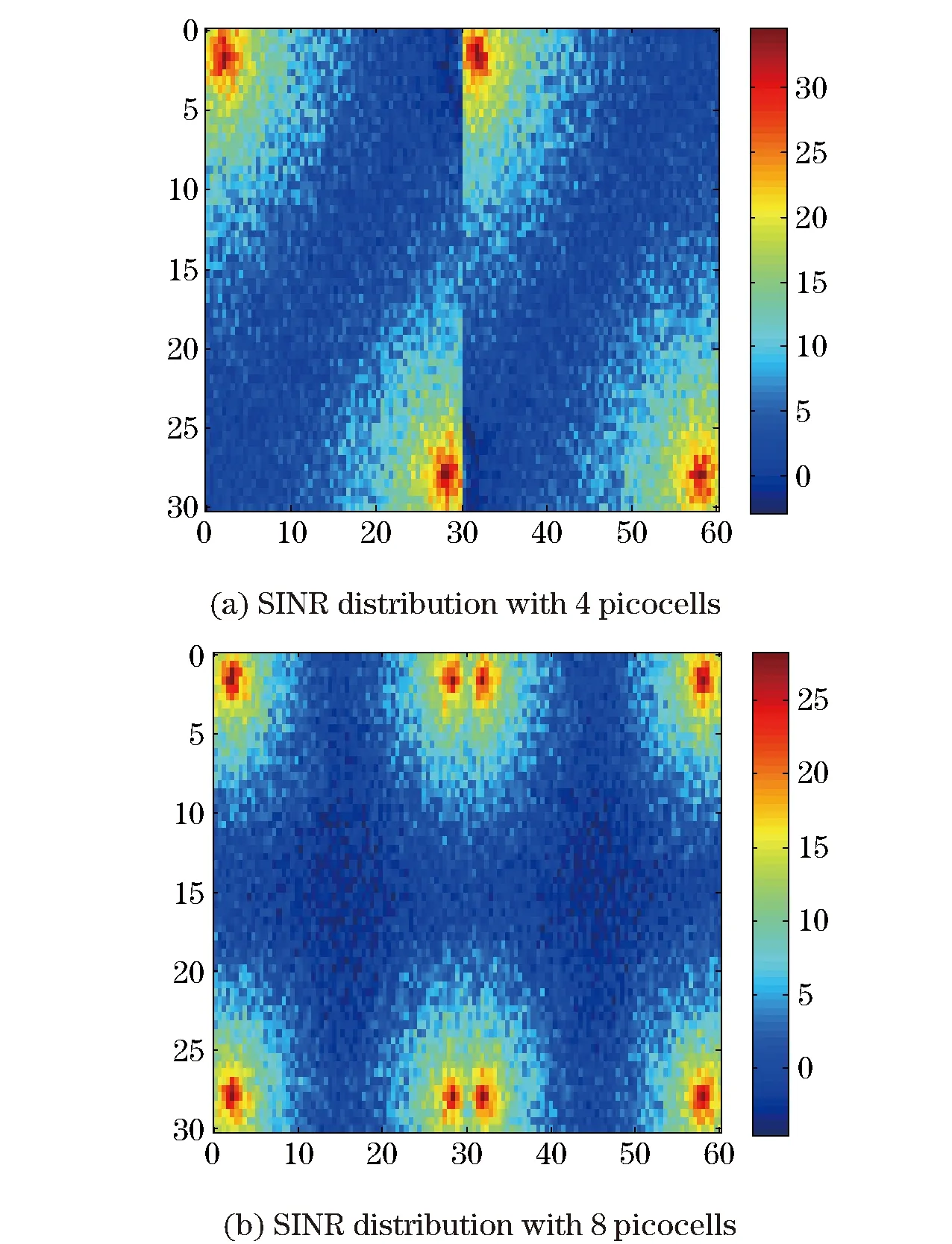
Fig.2 SINR distribution in two scenarios
Fig.3 shows the CDF curves of user transmitting rate calculated by Shannon capacity in two scenarios. Although the SINR distribution is worse in 8 picocells, the rates are higher compared with 4 picocells because of double resources. In addition, the rate improvement of the edge users is not obvious from 8 picocells to 4 picocells since these two curves are close to each other at the beginning. The obvious improvement occurs at the higher rate area and this is unfair for those users with a bad channel condition or the users far from pico stations. Moreover, when the required rate is low, there is little promotion in the number of satisfied users. The reason is that the pico stations transmit with maximum power no matter where the user is. It is not necessary to allocate too much power to the users which are close to pico stations because they have a good channel condition. The excess power will cause much interference to other users in adjacent picocells. The transmitting power of each user therefore should be limited to make more users work above their required rate.

Fig.3 Averaged total rate under rate constrained power control case
2 Distributed power allocation algorithm
To tackle the problem mentioned above, a distributed power allocation algorithm is proposed to allocate proper transmitting power of each user without any exchanging information between pico stations. More users will be able to achieve their required rate and the perceived experience of edge users is promoted.
In an OFDMA system, user’s transmitting rate is the sum of rate on each resource block (RB)[7]. For the reason that we only pay attention to power allocation algorithm, the RB are allocated to users in a random way followed Round Robin (RR) scheduling algorithm. Letri,kdenote the transmitting rate of userion thekthRB. According to the Shannon formula, the rate of useriis defined as
(1)
whereNiis the set of RB allocated to useri. TheSi,kis the SINR for the userion thekthRB andBdenotes the bandwidth of one RB. If we assume that the power on each of user is same and other adjacent pico stations transmit with the maximum power, the SINR on each RB of one user will be the same and Eq. (1) can be rewritten as
|Ni|Blog2(1+Si,k)=
Wilog2(1+Si,k)
(2)
whereWidenotes the bandwidth allocated to the useri. If we letRidenote the required rate of useri, the required SINR of userion thekthRB denoted byS′i,kwill be
S′i,k=2Ri/Wi-1
(3)
In another way, the SINR of userion thekthRB can be denoted by
(4)

Aseachuserassumesotherpicostationstransmitwithmaximumpower,whichistheworstsituation,thetransmittingpowerofpicostationjonthekthRBtosatisfytherequiredrateofusericanbeobtainedfromEq. (3)andEq. (4)by
(5)
wherePj,k,maxorPt,k,maxdenotes the maximum transmitting power of pico station on thekthRB. For simplicity, we assume that the power constraint on each RB is the same. So,Pj,k,max=Pmax/N, whereNis the number of RB of each pico station. The second formula in Eq. (5) means the actual transmitting power cannot exceed the maximum value.
If all users use this algorithm to decide their transmitting power, the most ofPj,kmust be lower than the maximum powerPj,k,max, which means that the practical situation must be better than the considered worst case. The actual transmitting rate should be higher than the required rate. However, with the rising of required rate, the situation will converge to the worst one, because more and more users can not satisfy their required rate and have to choose the maximum power.
3 Simulation results and discussions
In this section, we conduct simulations to demonstrate the performance improvement of the proposed distributed power allocation algorithm. The simulation model is illustrated in Fig.1 and the simulation parameters are listed in Tab.1.

Tab.1 Simulation parameters
3.1 Pico stations without periodical change in rate requirement
The simulation is performed in two rooms with 2 or 4 pico stations in each corner. The rooms are separated by a wall with 20 dB attenuation. For comparison, we have performed four situations, which are 4 pico stations without power control, 4 pico stations with power control, 8 pico stations without power control, and 8 pico stations with power control.
Fig.4 shows the calculative distribution function (CDF) of user transmitting rate with required rate equaling 500 kbit/s. After using proposed power allocation algorithm, the CDF curves will become sharper. That means the fairness of users has been improved. Take the 8 picocells with/without power control for example. The percentage of users whose transmitting rate is larger than 500 kbit/s varies from 83% to 99% after controlling transmitting power. Although there is some loss in high-rate users and total transmitting rate, more users will achieve their required rate and this is the real improvement of user experience.
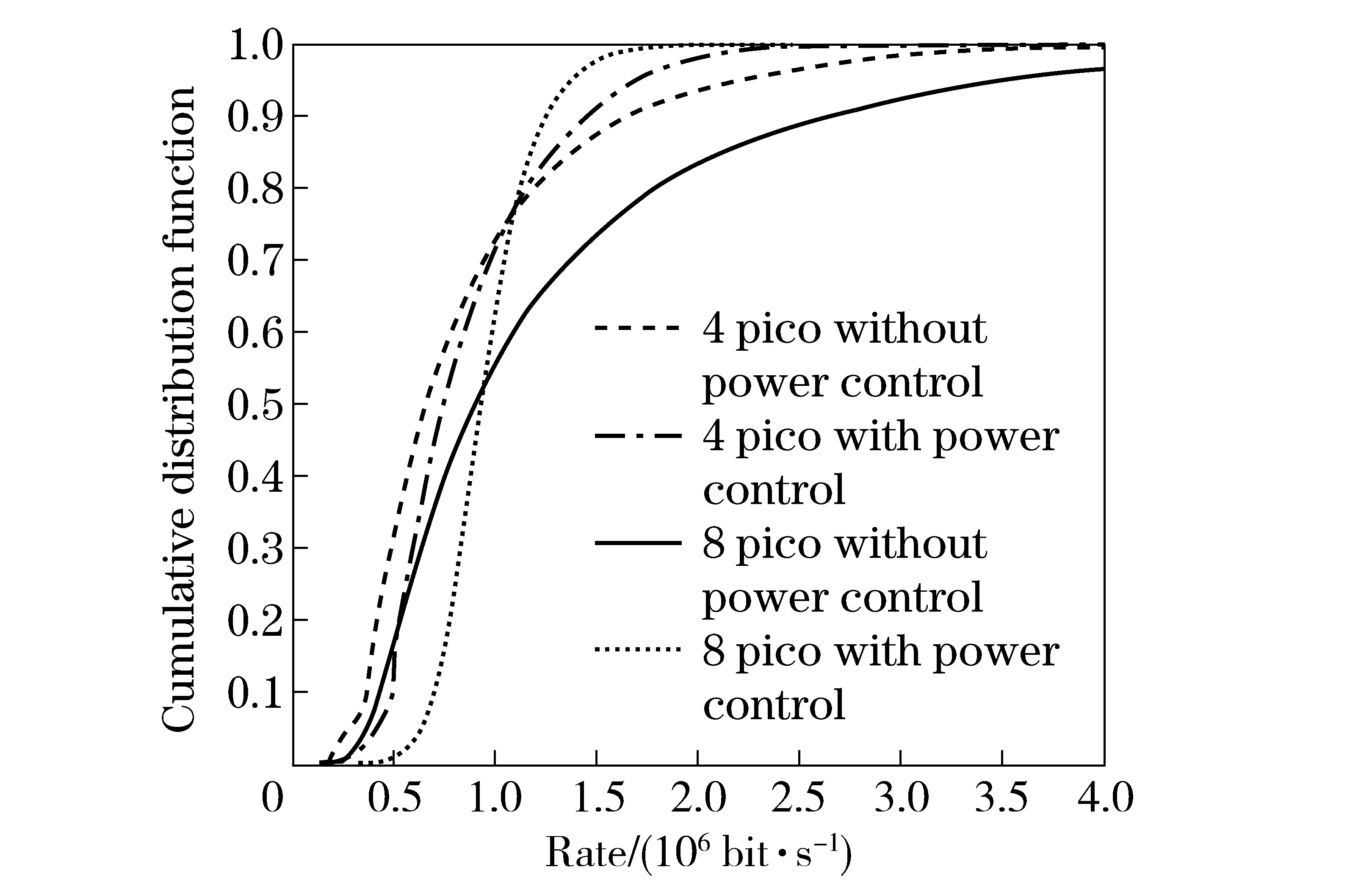
Fig.4 Comparison of transmitting rate with/without power control
Comparison of the transmitting rate of 4 picocells and 8 picocells shows that the power allocation algorithm is more efficient in 8 picocells scenario. This is because the interference in 8 picocells is much stronger than 4 picocells, which makes the interference mitigation algorithm more efficient. Another reason is that the transmitting power cannot be reduced too much since it is more difficult for users in 4 picocells scenario to satisfy the required rate.
3.2 Pico stations with periodic change in rate requirement
Actually, the rate requirement or SINR requirement will not keep the same all the time. It varies in different spots at different time. To tackle this problem and evaluate the adaptiveness of proposed power allocation algorithm, a scenario which represents this characteristic is introduced. The scenario is similar to the previous one which has two separated 30 m by 30 m rooms with 8 pico stations each in the corner (Fig.1). The difference is that we assume the pico station 1, 4, 5 and 8 have a periodic variation in rate requirement. In the simulation this four pico stations are switching rate requirement simultaneously. The normal rate requirement is 500 kbit/s, which happens in time interval 0-T0, and low rate requirement is 200 kbps, which happens in time interval T0-T, where T0 denotes the time of pico station 1,4,5,8 working in normal rate requirement and can be changed according to different circumstances. The lengths of these two time interval are the same in our simulation. The simulation time is set to 10T and the result of users’ transmitting rate is shown in Fig.5.
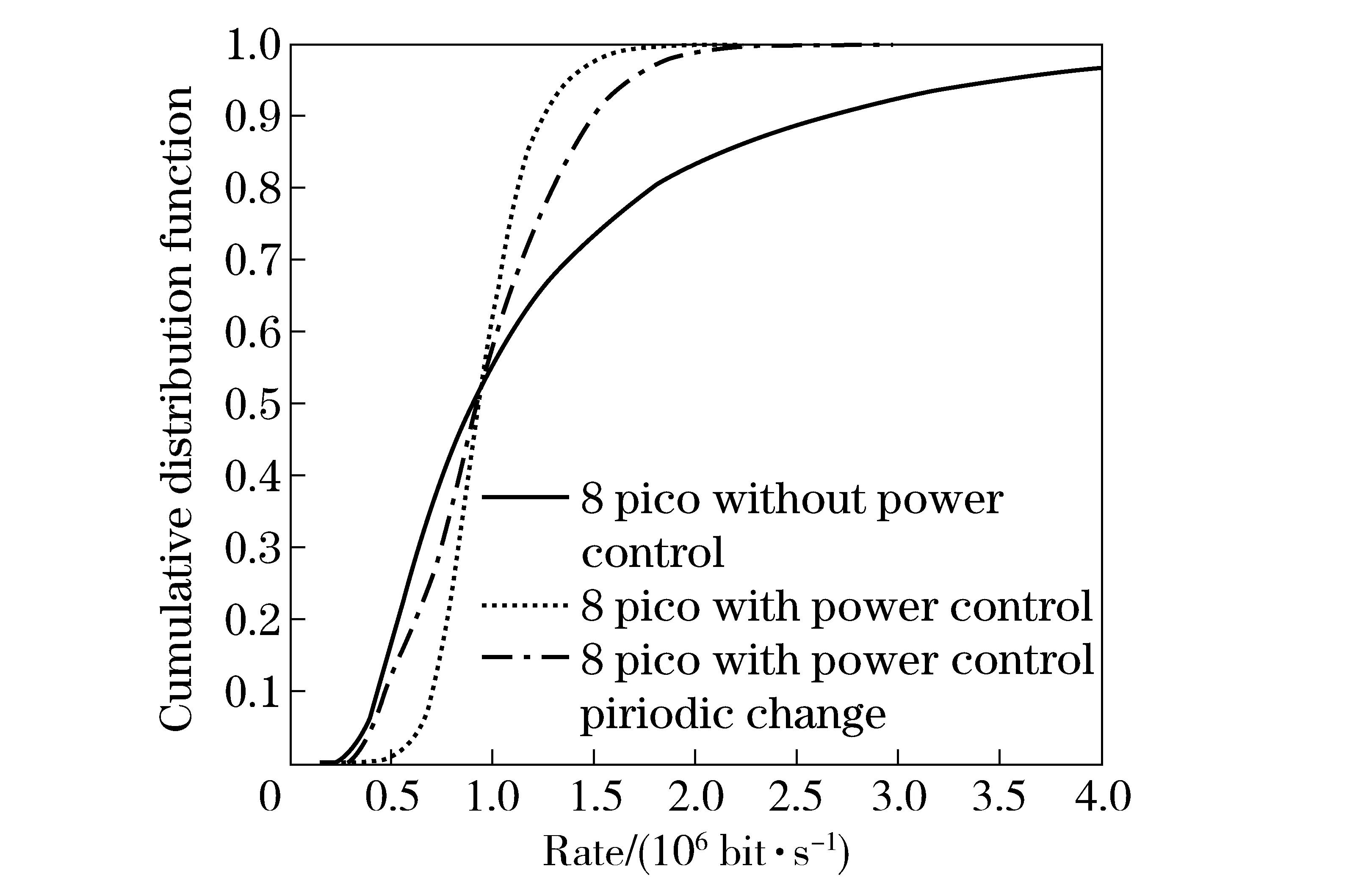
Fig.5 Comparison of transmitting rate considering periodical change
In Fig.5, there is a reduction in transmitting rate of edge users when considering periodical variation of required rate. However, it does not mean the user experience has been degraded because of lower requirement in time interval T0-T. In fact, compared with previous scenario without periodical variation, the number of users which can achieve the required rate almost does not change, which will be shown later. On the other hand, the transmitting rate of high-rate users has a promotion comparing with previous scenario. This is because the interference to high-rate users is much lower when required rate is low in time interval T0-T.
Fig.6 shows the sum of user transmitting rate in each picocell, which can be considered as the capacity of each pico station approximately. The capacity of pico stations without power control is higher than other two situations. However, its main contribution comes from the users have a good channel condition and it is not fair to edge users. Comparing the red bar with the green one, the capacity of pico stations numbered 1, 4, 5 and 8 will have a reduction. This is because the lower required rate in time interval T0-T when considering periodical change of users required rate. On the other hand, lower rate requirement will also mitigate the interference to the other four pico stations and result in an increment of transmitting rate of users in pico stations numbered 2, 3, 6, and 7.
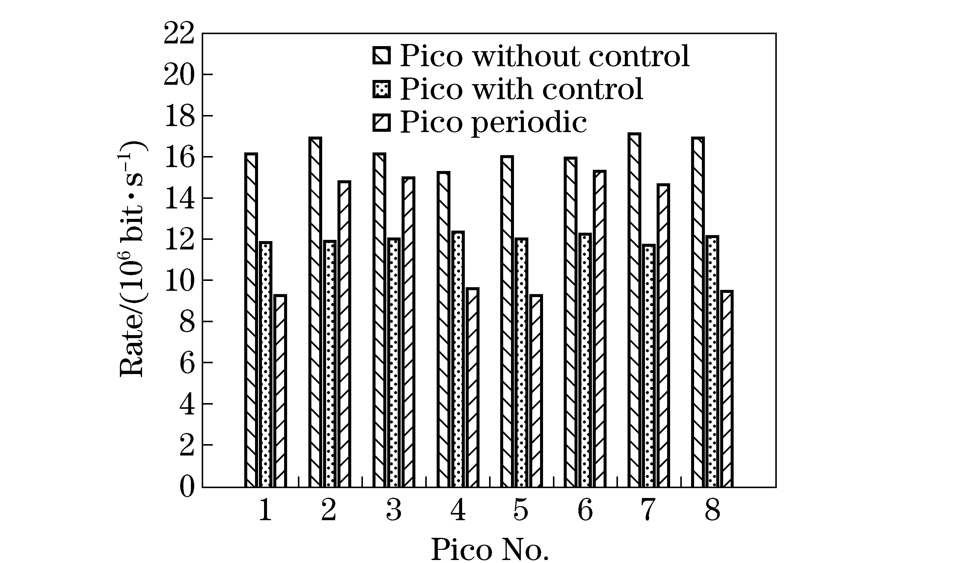
Fig.6 Transmitting rate of 8 picocells
Finally, we take both power consumption and the outage ability into account as depicted in Fig.7. The normalized outage ability is defined as the number of users which can achieve the required rate divided by the number of users. And the normalized power consumption is defined as the sum of transmitting power divided by the transmitting power consumption without power control, i.e. the sum of maximum transmitting power. As we mentioned above, although the total transmitting rate has been degraded, the number of user achieving required rate will increase after using proposed power allocation algorithm. Moreover, from the perspective of power consumption, the proposed algorithm can save more than 50% energy without loss in outage ability. Especially, the energy saving will be further improved when considering periodical variation of required rate. That indicates the proposed algorithm efficiently promote the user experience and demonstrates the adaptiveness of algorithm. Fig.8. illustrates the energy efficiency of three situations. It is obvious that without power control system has to work in low efficiency and the improvement is observable after using proposed algorithm. The periodical adaptability of proposed power control scheme is also satisfactory according to simulation results.

Fig.7 Comparison of normalized power consumption and outage ability

Fig.8 Energy efficiency of three situations
4 Conclusion
In this paper, we propose a distributed power allocation algorithm over indoor multi-pico stations to permit pico stations to adjust the transmitting power of each user based on the rate requirement. The algorithm is low-complexity and does not need any exchanging information between pico stations. Simulation results confirm that the proposed power allocation algorithm can promote the fairness and user experience with a lot of energy being saved compared with traditional maximum transmitting power scheme.
[1] Osman H, Zhu H L, Alade T. Deployment of distributed antenna systems in high buildings[C]∥IEEE 73rd Vehicular Technology Conference (VTC Spring), San Francisco, United State, 2011.
[2] Chandrasekhar V, Andrews J, Gatherer A. Femtocell networks: a survey [J]. IEEE Communication Magazine, 2008, 46(9): 59-67.
[3] Lee H W, Modiano E, Le L B. Distributed throughput maximization in wireless networks via random power allocation [J]. IEEE Transactions on mobile computing, 2012, 11(4): 577-590.
[4] Li B. An effective inter-cell interference coordination scheme for heterogeneous network [C]∥IEEE 73rd Vehicular Technology Conference (VTC Spring), San Francisco, United State, 2011.
[5] Quek T, Cheung W C, Kountouris M. Energy efficiency analysis of two-tier heterogeneous networks [C]∥11th European Wireless Conference, Vienna, Austria, 2011.
[6] Gupta N K, Banerjee A. Power and subcarrier allocation for ofdma femto-cell based underlay cognitive radio in a two-tier network [C]∥IEEE 5th International Conference on Internet Multimedia Systems Architecture and Application, Karnataka, India, 2011.
[7] Xie L L, Hu C J, Wu W J, et al. Qoe-aware power allocation algorithm in multiuser ofdm systems [C]∥7th International Conference on Mobile Ad-hoc and Sensor Networks (MSN), Beijing, China, 2011.
[8] 3GPP. TR 36.814, Further advancements for E-UTRA physical layer aspects[S]. v9.0.0 ed. Sophia Antipolis, France: 3GPP. 2010.
(Edited by Cai Jianying)
10.15918/j.jbit1004- 0579.201524.0214
TP 391 Document code: A Article ID: 1004- 0579(2015)02- 0227- 06
Received 2013- 12- 22
Supported by National S & T Major Program of China(2013ZX 03003002-003)
E-mail: feizesong@bit.edu.cn
猜你喜欢
杂志排行

Journal of Beijing Institute of Technology的其它文章
- Nonlinear symbolic LFT model for UAV
- Novel scheme of high precision inertial measurement for high-speed rotating carriers
- Study on influencing factors of adapters separating with the underwater missile
- Fast-solving method for air-to-surface guided bombs’ allowable attack area
- Design and analysis of mechanical self-destruction and self-neutralization mechanism for submunition fuze
- Resilience approach for heterogeneous distributed networked unmanned weapon systems