Design of speed controller for electronic fuel injection gasoline generator based on feed-forward PID control
2015-03-29ZHAOZiqingLIUChangwenZHANGPing
ZHAO Zi-qing, LIU Chang-wen, ZHANG Ping
(1. State Key Laboratory of Engines, Tianjin University, Tianjin 300072, China;2. Department of Energy Engineering, Zhengjiang University, Hangzhou 310027, China)
Design of speed controller for electronic fuel injection gasoline generator based on feed-forward PID control
ZHAO Zi-qing1, LIU Chang-wen1, ZHANG Ping2
(1.StateKeyLaboratoryofEngines,TianjinUniversity,Tianjin300072,China;2.DepartmentofEnergyEngineering,ZhengjiangUniversity,Hangzhou310027,China)
As for the application of electronic fuel injection (EFI) system to small gasoline generator set, mechanical speed controller cannot be coupled with EFI system and has the shortcomings of lagged regulation and poor accuracy, a feed-forward control strategy based on load combined with proportional-integral-differential (PID) control strategy was proposed, and a digital speed controller applied to the electrical control system was designed. The detailed control strategy of the controller was introduced. The hardware design for the controller and the key circuits of motor driving, current sampling and angular signal capturing were given, and software architecture was discussed. Combined with a gasoline generator set mounted with EFI system, the controller parameters were tuned and optimized empirically by hardware in loop and bench test methods. Test results show that the speed deviation of generator set is low and the control system is stable in steady state; In transient state the control system responses quickly, has high stability under mutation loads especially when suddenly apply and remove 100% load, the speed deviation is within 8% of reference speed and the transient time is less than 5 s, satisfying the ISO standard.
gasoline generator; digital speed controller; electronic fuel injection (EFI); feed forward; proportional-integral-differential (PID) control
At present, with the intensification of environmental and energy problems, as well as the increasingly stringent emission regulations[1], people have paid more attention to the fuel consumption and emissions of internal combustion engine while carburetor oil supply and mechanical devices are still widely used in small gasoline generator set. Carburetor has the shortcomings of lagged high fuel consumption and bad emission[2]. Due to the damping and friction of transmission, mechanical speed controller method has the shortcomings of regulation and low accuracy, which restrict the performance of the product. Compared with the carburetor, electronic control technology has advantages in fuel consumption and emission. It can not only meet more stringent emission standards but also increase product competitiveness. As a result, it becomes a way to replace the traditional carburetor[3]. Therefore, the development of digital speed controller that matches the electronic injection (EFI) system is an important guarantee of the application to the small generator set.
Because of the torque characteristics difference between diesel and gasoline engines, research on digital speed controller in diesel engine has been done a lot. Speed control of large diesel generator sets has been studied based on neural network control, sliding model control, feed-forward control with multiple inputs and neural network (PID) control strategy, etc., by the domestic and foreign scholars[4-7]. But the strategies above are not suitable for real-time control of small gasoline generators because of design complexity and a large amount of calculation. In addition, the production cost increases due to higher performance demand of control chip. Digital speed controller of gasoline generator has been studied mainly with traditional carburetor type. CHENG Gou-ying[8]designed constant speed control strategy that switches between PID algorithm and fuzzy algorithm according to the size of the generator terminal load. WU Ming-tao[9]designed digital speed controller with adjustable engine target speed based on PID algorithm. Simulation results have been analyzed based on different constant speed control strategies, including fuzzy PID and synovial control[10-12].
To achieve practical and reliable digital speed controller, this paper designed a double closed loop speed control strategy with the feedback of engine speed and electronic throttle position of EFI system based on PID control algorithm, which ensures the stability of control. The biggest disturbance of speed is from load mutation. To further improve the response of the controller during load mutation, a feed-forward strategy based on load was introduced. According to established control strategy, the hardware and software systems of controller were designed, and bench tests were conducted combined with the EFI gasoline generator set. The results show that the steady speed deviation of gasoline generator set is small under different loads. In case of load mutation, the controller responds quickly with little stable time, small speed fluctuation and strong robustness.
1 Electronic fuel injection theory
The original gasoline generator set adopts carburetor oil supply way and mechanical speed regulation method. The engine is of single cylinder and four strokes. The engine displacement is 439 mL and the rated power is 7 kW. The generator output is alternating current (AC) of two phases. The single-phase rated voltage is 120 V and the frequency is 60 Hz. The structure of EFI system is shown in Fig.1, mainly including electronic control unit (ECU), injector, throttle body assembly (throttle body and throttle position sensor (TPS)), oxygen sensor, crankshaft position sensor, cylinder temperature sensor, etc. ECU captures the angular signal by means of crankshaft position sensor. The crankshaft position sensor produces one angular signal for each engine cycle. The time interval between two adjacent angular signals is the revolution time of one engine cycle, therefore engine speed can be calculated. The current throttle opening is sampled by throttle position sensor. Based on speed throttle position method[13]for intake air mass flow measurement, the intake air quantity is calculated. The air quantity is modified by the sampling value of the cylinder head temperature sensor and the intake air temperature sensor. Then the fuel injection amount is calculated by combining with the given target air-fuel ratio. The fuel injection amount is finally corrected by the feedback signal of oxygen sensor. The fuel injection pulse width of driving injector is precisely calculated according to the fuel injection amount. Gasoline is injected into intake pipe and the optimum ignition angle is calculated according to the current speed and load.
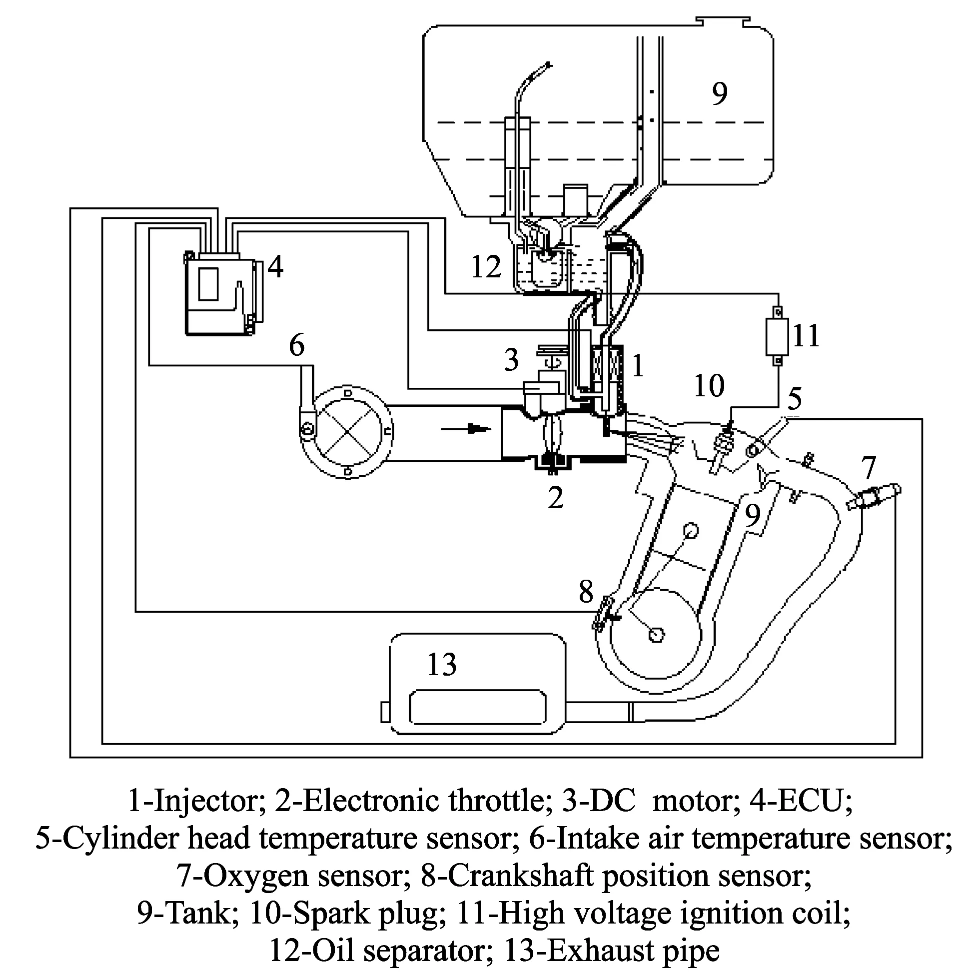
Fig.1 Block diagram of electric fuel injection system
According to EFI principle, the change of intake air quantity (the electronic throttle opening) will bring about the change of fuel injection quantity. Therefore, the output torque of generator will change and speed control can be realized.
2 Speed control strategy
2.1 Overall design of speed control strategy
The overall design of speed control strategy is shown in Fig.2.
It can be seen that the speed control system mainly consists of throttle controller (PIDtps), duty ratio controller (PIDpwm) and feed-forward channel based on load.
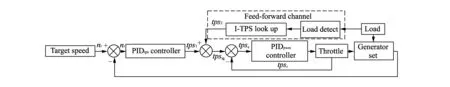
Fig.2 Block diagram of speed control strategy
PIDtpscontroller adjusts target throttle position (tpstg) according to the current speed feedback. Heretpstgis the expected throttle opening to keep the engine running at the target speed. In the steady state,tpstgis only adjusted by PID controller according to the feedback speed. A stable load corresponds with a stable throttle opening, therefore there is a stable co-relationship betweentpstgand the load which can be acquired through sampling throttle position sensor and load sensor in a steady state. When load mutation, based on the output of PIDtpscontroller (tps1),tpstgis adjusted by joining a feed-forward throttle opening quantity (tps2) which corresponds with the mutation amount of load by looking up the acquired co-relationship in the steady state.
PIDpwmcontroller adjusts the duty ratio of the drive DC motor by the throttle position (tpsr) as a local feedback. Thus the rotation speed of the DC motor can be controlled to ensure that the throttle position reaches a desired valuetpstg.
2.2 Incremental PID control strategy
For the purpose of calculating target throttle position and controlling DC motor, PIDtpscontroller and PIDpwmcontroller are designed based on incremental PID algorithm.
The speed deviation of PIDtpscontroller is
wherekis sampling cycle;ne(k) is speed deviation of thek-th cycle,nt(k) is constant target speed andnr(k) is engine speed of thek-th cycle.
The incremental output Δut1(k) of PIDtpscontroller is
wherene(k-1) is the circulation speed deviation of the (k-1)th cycle,ne(k-2) is the circulation speed deviation of the (k-2)th cycle,Kp1is the proportion constant of PIDtpscontroller,Ki1is the integral constant of PIDtpscontroller andKd1is the differential constant of PIDtpscontroller.
The throttle position deviation of the PIDpwmcontroller is
wherejis the sampling moment;tpse(j) is the throttle position deviation at momentj;tpstg(j) is the expected throttle position at momentjandtpsr(j) is the actual throttle position at momentj.
The incremental output of PIDpwmcontroller can be calculated by
wheretpse(j-1) is the throttle position deviation at momentj-1;tpse(j-2) is the throttle position deviation at momentj-2;Kp2is the proportion constant of PIDpwmcontroller;Ki2is the integral constant of PIDpwmcontroller andKd2is the differential constant of PIDpwmcontroller.
2.3 Feed-forward control strategy
The coil current of the stator changes first when the generator encounters load mutation. Then the electromagnetic torque of the rotor changes with the air gap magnetic field. The mutation of electromagnetic torque makes engine output torque be out of balance, which leads to the mutation of engine speed. Because the current change is prior to speed change, a feed-forward strategy can be introduced into the throttle control by testing load current to suppress speed fluctuation in the state of load mutation.
The single phase alternating current of generator is
whereI0is the current amplitude, A;ωis the frequency of alternating current, Hz;tis the time, s;Iis the current at momentt, A;U0is the rated voltage, V;ρis the phase angle of current and voltage, rad;Uis the voltage at momentt, V.
The resistance load of the generator side is studied in this article. The average power of the generator is
In Eq.(6), the output voltage of generator (U0) is seen as a fixed value. The output current of generator is proportional to the average output power, and it corresponds to the throttle position in a steady running state. Therefore in this article the throttle opening change corresponding to the change of current amplitude in the steady state is designed to be a feed-forward quantity of load mutation. The controller samples current amplitude per cycle, thus the feed-forward control strategy is designed as
where ΔIis the change of current amplitude;I0(k) is the current amplitude of thek-th cycle;I0(k-1) is the current amplitude of the (k-1)th cycle;f(·) is the corresponding relation between the current change and the throttle opening change;ut2(k) is the throttle opening change corresponding to the current amplitude change.
The wire current is sampled by current transformer. In the steady state, the current amplitudes under different loads are sampled by means of a large number of experiments. The relationship curve between the current amplitude sampling change and TPS sampling change is shown in Fig.3, and it is given according to the sampling value of single chip microcomputer.
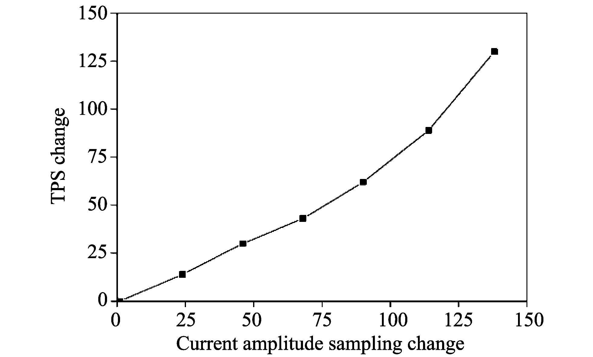
Fig.3 Relationship curve between TPS sampling change and current amplitude sampling change
3 Speed controller design
3.1 Hardware design
The structure of speed controller hardware is shown in Fig.4. The 16-bit MC9S12G128 single chip microcomputer is chosen as the core. The bus frequency is set at 16 MHz and the kernel frequency is 32 MHz. The structure of speed controller hardware consists of signal acquisition, motor driver, power supply and communication module, etc.
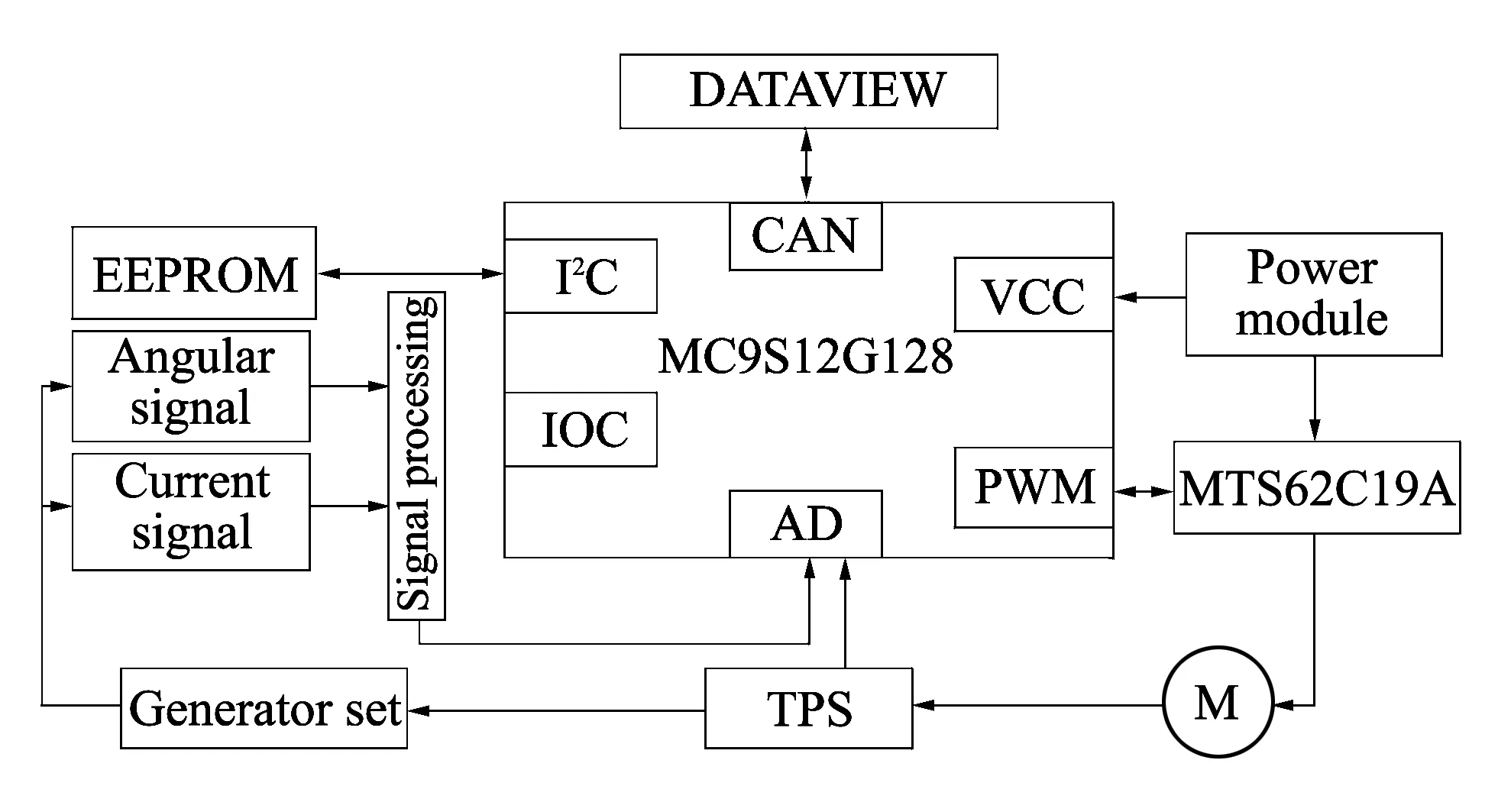
Fig.4 Block diagram of speed controller hardware
3.1.1 Motor driver design
The throttle body of EFI system is self developed, which is driven by a DC motor. The DC motor is a permanent magnet DC motor with rated voltage of 12 V, coil resistance is (16±1) Ω and the rated speed of 138 rpm. The DC motor is controlled by the speed controller and the current throttle position is sampled by TPS which is connected to the throttle shaft.
The two-way bridge driving chip MTS62C19A is selected as the driver chip of DC motor, which can bilaterally control two DC motors at the same time. One H bridge of the chip is chosen to drive the DC motor. The peripheral circuit of motor driver module is shown in Fig.5.
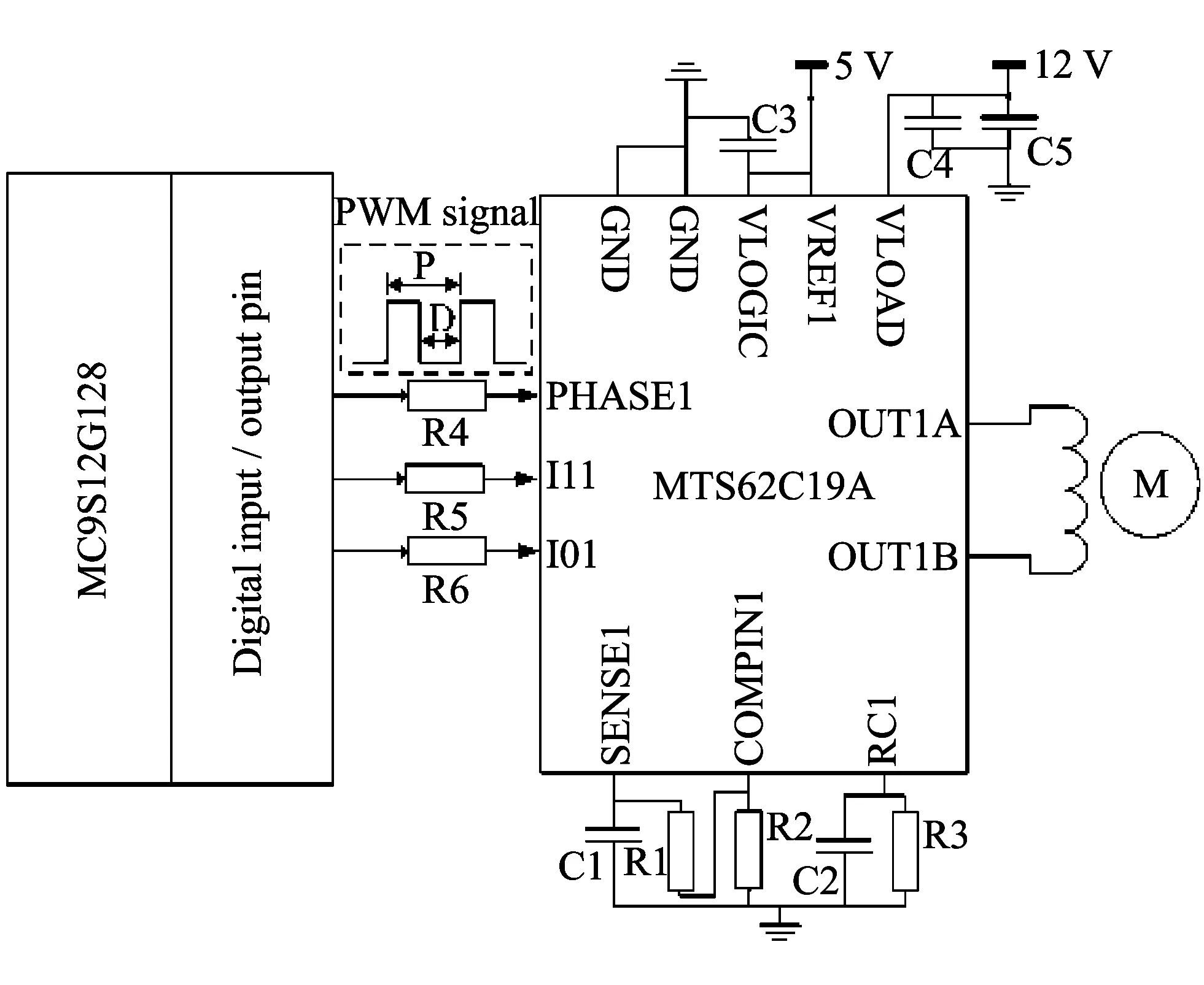
Fig.5 Schematic diagram of DC motor driver circuit
OUT1A and OUT1B are pins that output driving current and connect with the ends of DC motor. The maximum driving current of the chip is
whereImaxis the maximum output current of chip, A;R1 is the sampling resistance, Ω;Urefis the reference voltage of pin VREF1, V.
The actually allowable output current is further controlled by I01 and I11 pin level, and the co-relationship between them is shown in Table 1.
Table 1 Co-relationship between output current and control level
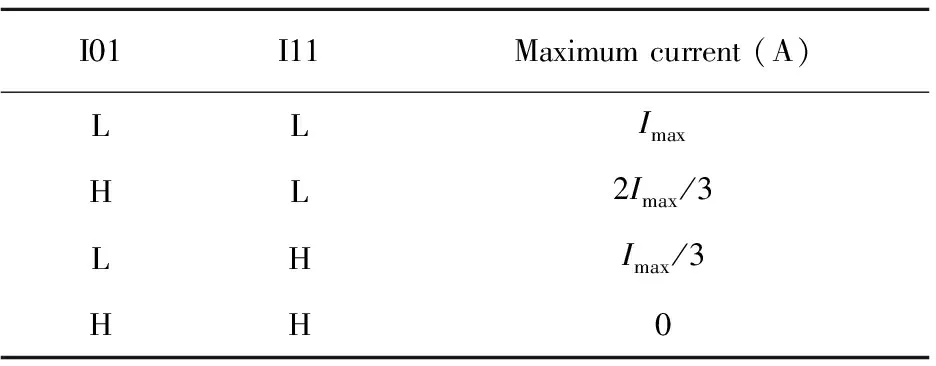
I01I11Maximumcurrent(A)LLImaxHL2Imax/3LHImax/3HH0
The R1 in driving circuit is 0.18 Ω. The reference voltage of pin VREF1 is 5 V. Pin I11 is designed to maintain a high level. The output current is controlled by pin level of I01. The allowable maximum output current is 0.93 A by calculation, which is greater than the locked-rotor current of DC motor. It meets the demands of the current when the DC motor is of the rated voltage. Pin PHASE1 controls current direction (rotation direction of DC motor). The motor rotates in forward direction when in a high level and reverses when in a low level. The input of pin PHASE1 is designed as the duty ratio signal. The duty ratio of pin PHASE1 is adjusted by PIDpwmcontroller to control the rotation direction and speed of DC motor.
3.1.2 Design of current sampling circuit
Load current is acquired by current transformer. The proportionally decreased current is fed into the sampling circuit, which triggers the single chip microcomputer to capture and sample the amplitude of the current. The sampling circuit is shown in Fig.6.
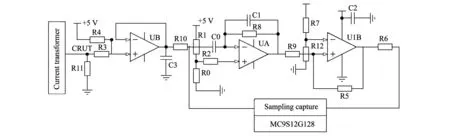
Fig.6 Schematic diagram of current amplitude sampling circuit
The primary/secondary coil ratio of current transformer is 800/1. On primary coil side, the maximum current can reach 75 A. The secondary coil side outputs the proportionally decreased current signal. Because the AD sampling pins of the single chip microcomputer needs voltage signal, the output current of the transformer is converted into voltage signal through the sampling resistor R11. The sampling of current amplitude is converted to the sampling of voltage amplitude. Since ECU does not have negative voltage, the input voltage value raises to 2.5 V through the voltage divider R3 and R4 to achieve the intact input of sine signal. Therefore, the positive power supply pin of the first amplifier UB is the sine signal with votage amplitude of 2.5 V.
The first level of the circuit is a voltage follower, which achieves the isolation from the outside signal and reduces the influence on sampling circuit. At the same time, the sampling voltage is limited to 5 V. The second level is a differentiator. The input waveform phase advances and the sine signal changes into cosine signal after differentiated. The third level is a hysteretic comparator. The cosine signal becomes square wave signal after comparison. The output waveforms of all levels are shown in Fig.7. At the moment corresponding to the falling edge of square wave, the capture function of the single chip microcomputer is triggered, and the interrupt handler immediately samples the voltage of the first level circuit. The sampling value minus the voltage value 2.5 V represents the current load.
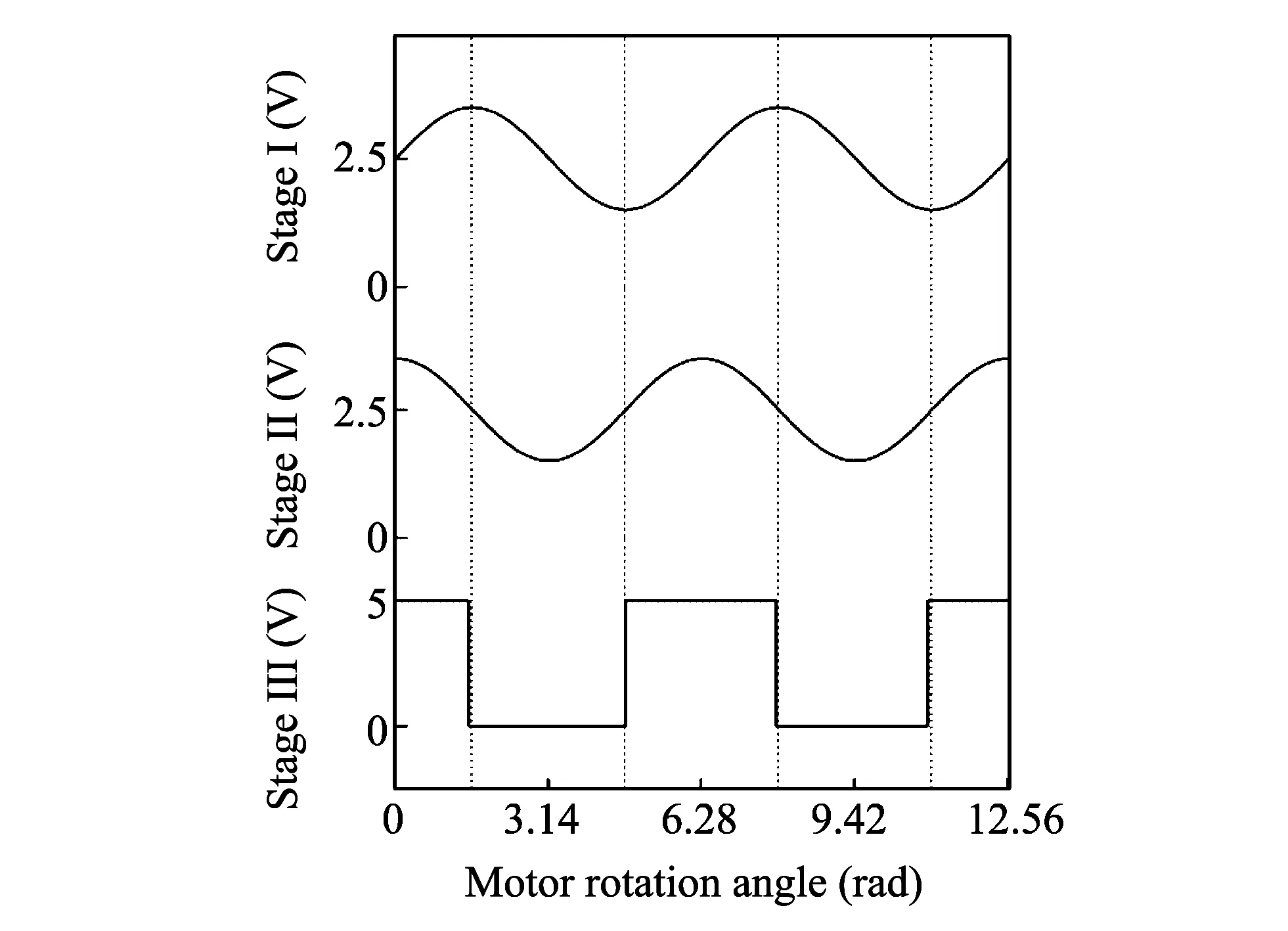
Fig.7 Output voltage wave diagram in different stages
3.1.3 Design of angular signal processing circuit
The engine speed is obtained through angular signal. The engine angular signal processing circuit is shown in Fig.8.
The crankshaft position sensor produces a standard angular signal per revolution of engine. The signal is an irregular sine voltage signal. After being produced by the capacitor filter, resistance divider and diode, the signal is sent to the base of the transistor which works in a saturation region. Then it is transformed into a square wave signal by the transistor, the falling edge is captured by single chip microcomputer, and the captured moment is the arriving moment of angular signal, which can be used to calculate the engine speed.
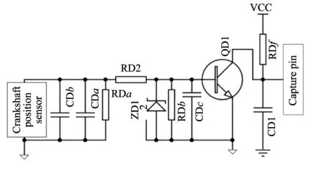
Fig.8 Schematic diagram of angular signal processing circuit
3.1.4 Design of power supply and communication module, etc
At for speed controller, the input voltage of power supply module is 12 V and 7805 chip converts 12 V to 5 V for single chip microcomputer and TPS. At the same time, the power module supplies 12 V voltage to the driver chip of DC motor. TPS and the throttle shaft driven by the DC motor are connected. The slide rheostat in TPS is driven while the throttle shaft rotates. It will change the output voltage of TPS. The TPS signal is sampled by the AD channel of the single chip microcomputer so that the current throttle opening can be acquired. The single chip microcomputer exchanges the data with self-developed DATAVIEW calibration system through serial asynchronous communication mode. The baud rate is set at 19 200 bps. The EEPROM is 24c02 for the storage of fixed parameters and state information of the speed controller.
3.2 Software design of speed controller
The software design of speed controller includes acceleration control of starting phase and constant speed control within the target speed range, which is shown in Fig.9. When the speed controller is powered on, the on-chip resources of MC9S12G128 are initialized first. Before the engine starts, the electronic throttle is initially adjusted by the speed controller to ensure that the opening of the throttle is in the range of initial values and the action of electronic throttle is normal. Before the angular signal comes, the TPS signal is sampled by the program. The acceleration process is defined as the process that the engine accelerates from the static to 3 300 rpm. The program identifies the process by the acceleration flag bit. When the speed exceeds 3 300 rpm, the acceleration flag bit is set. After the acceleration process ends, constant speed control is carried out which is shown in the gridline box of Fig.9. In order to ensure the stability of acceleration, the value oftpstgincreases 1 sampling unit every eight engine circles, achieving the slow transition to constant speed control. After the engine runs into the constant speed control,tpstgis calculated by the feed-forward PID control strategy. According totpstgandtpsrper cycle, the duty ratio of DC motor is adjusted by PIDpwmcontroller driving the throttle to the desired opening.
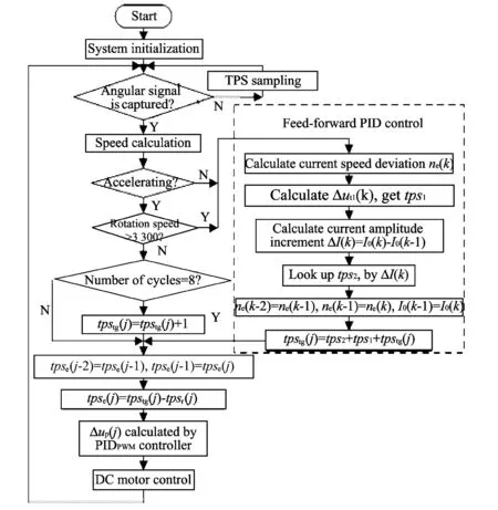
Fig.9 Software flow chart of speed controller
4 Experiment
A single-cylinder gasoline generator set mounted with EFI system was studied. Bench test was conducted to verify the validity and reliability of the speed controller, and DATAVIEW calibration system was used to monitor and modify parameters of the operating system.
Before the speed controller was put in to use, the parameters of PIDpwmcontroller and PIDtpscontroller should be tuned. PIDpwmcontroller was tuned by hardware in the loop method[14], namely, by simulating the engine angular signals, the PIDpwmcontroller can control DC motor at the target speed. A step disturbance was applied totpstgby calibration system; According to engineering-tuning method[15], the parameters of the DC motor controller was adjusted until the step response curve of DC motor is satisfactory, as shown in Fig.10.
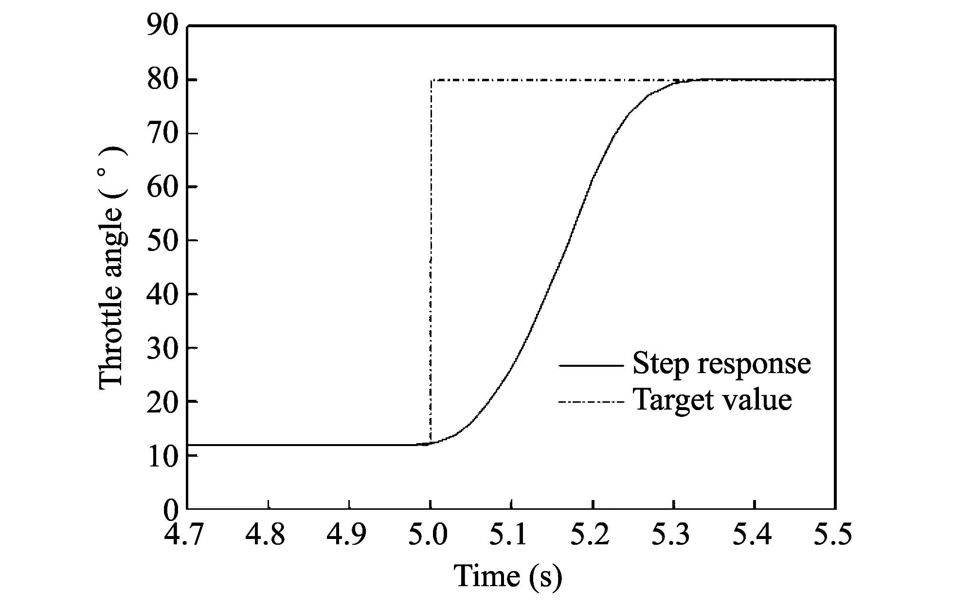
Fig.10 Step response curve of electronic throttle
Based on the tuned PIDpwmcontroller, the parameters of PIDtpscontroller were tuned through the bench test. A step disturbance was applied to the target speed by the calibration system, the parameters of controller was adjusted until the step response curve of the engine speed was acceptable, as shown in Fig.11 The fixed parameters of PIDtpscontroller are as follows:Kp1=0.33,Ki1=0.25 andKd1=0.1; The fixed parameters of PIDpwmcontroller are as follows:Kp2=0.37,Ki2=0.01 andKd2=0.2.
The control process is divided into acceleration and constant speed control. During acceleration, to ensure the stability and prevent fluctuation of throttle caused by rapid change oftpstg,tpstgis limited to increase one unit every eight cycles of the engine. Therefore, the tuned PIDpwmcontroller can achieve stable driving of DC motor, and the acceleration curve is shown in Fig.12.
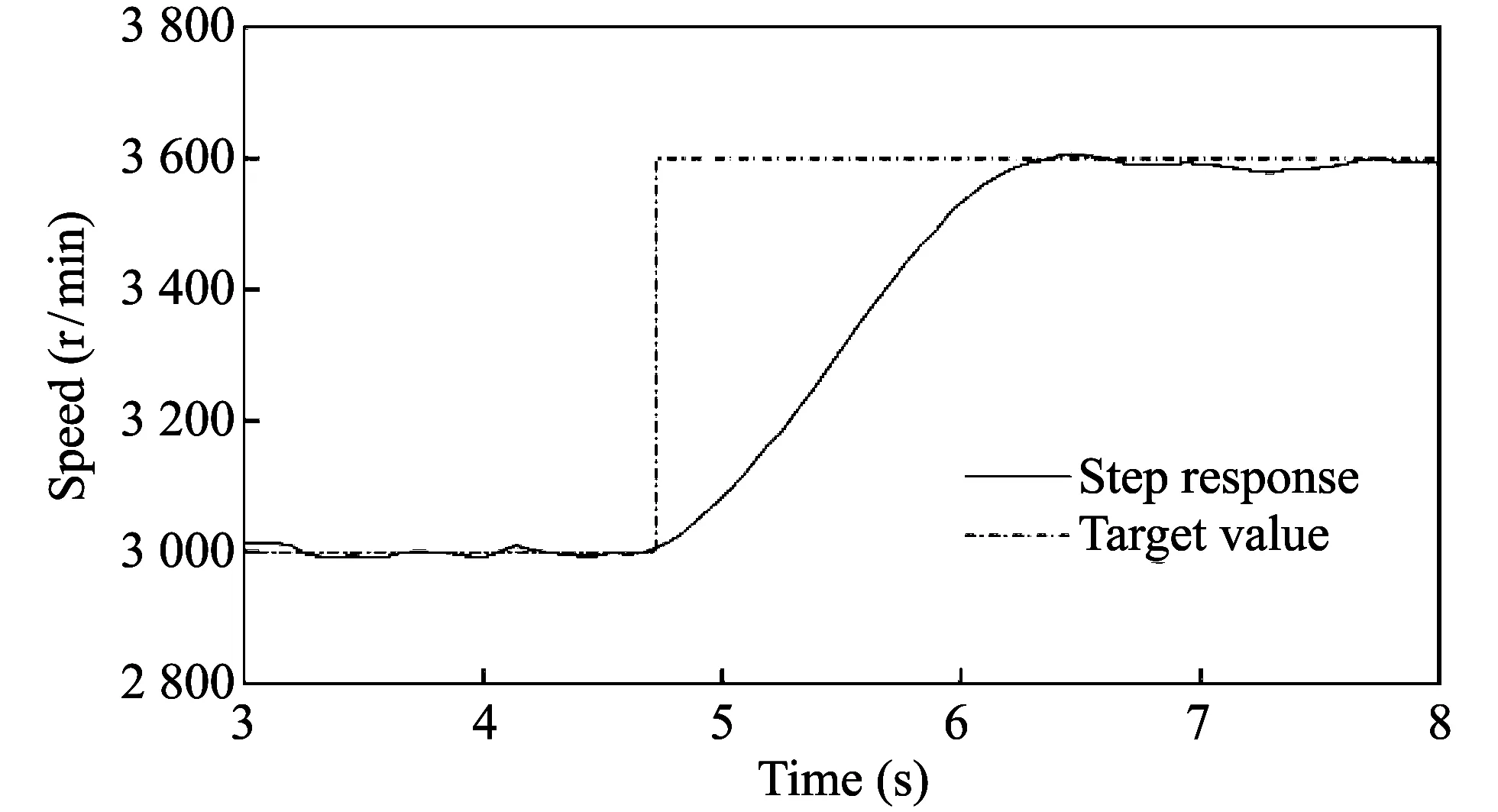
Fig.11 Step response curve of engine speed
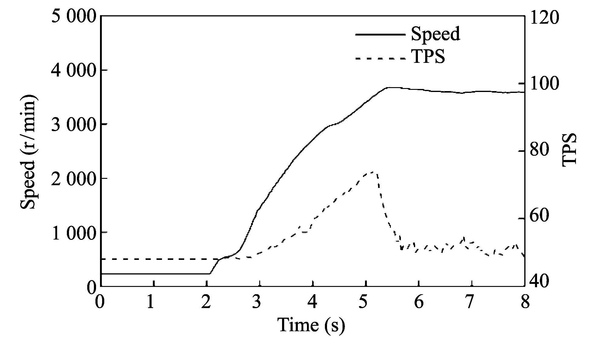
Fig.12 Acceleration curve of generator set
During 2-5 s of acceleration process,tpstgincreases nearly linearly, the speed curve is smooth and stable without fluctuations; the TPS sampling curve drops after 5 s;tpstgis controlled by feed-forward PID control strategy and constant speed control process is carried out. The smooth transition of acceleration proves the acceleration strategy is effective.
To verify the speed controller characteristics, a large number of experiments by suddenly applying and dumping 100% load were conducted according to the test criteria for the generator[16], and control effects of PID and feed-forward PID(F_PID) were compared. The curves are shown in Figs.13-16.
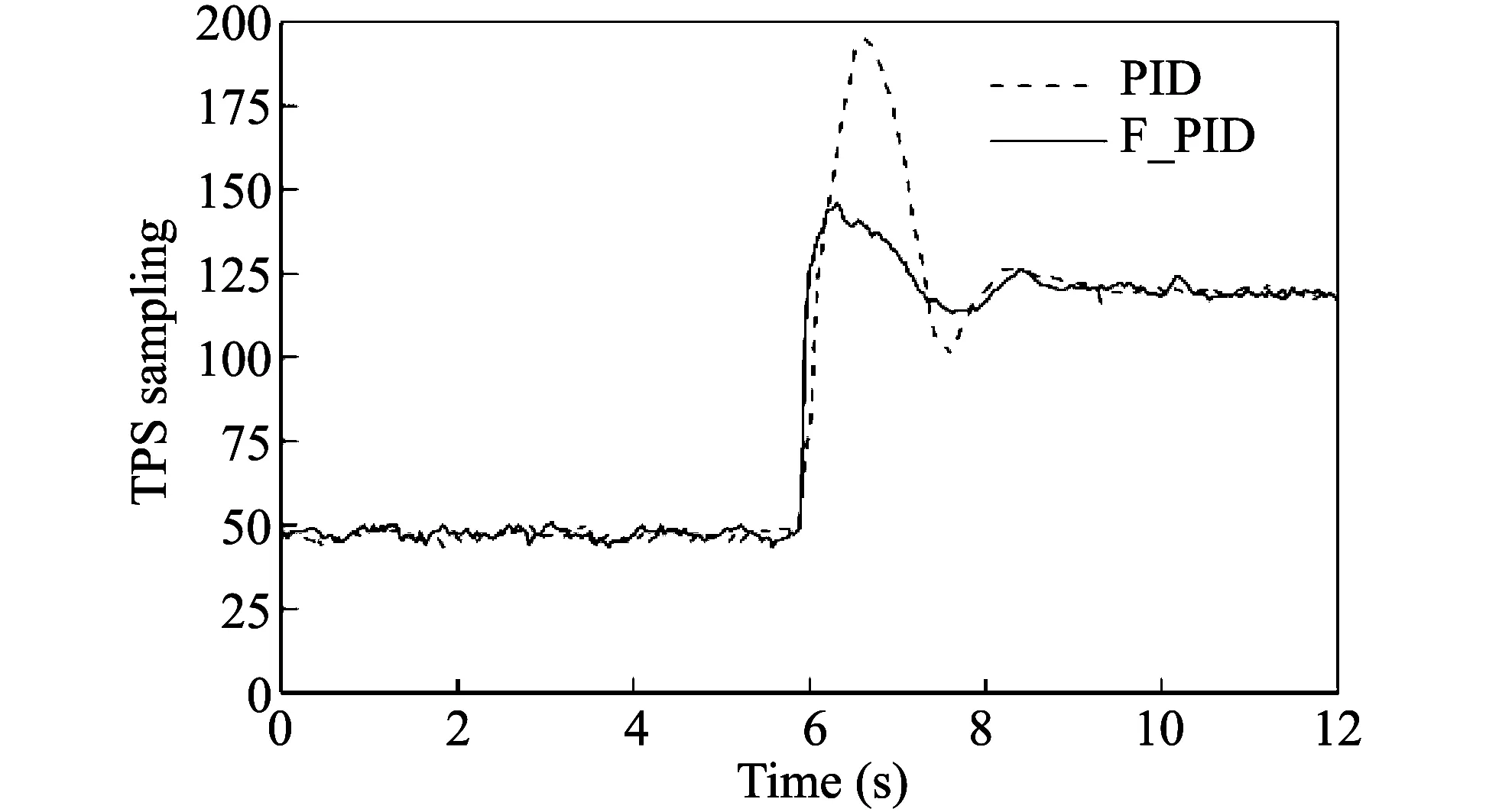
Fig.13 Comparison of TPS when 100% load is suddenly applied
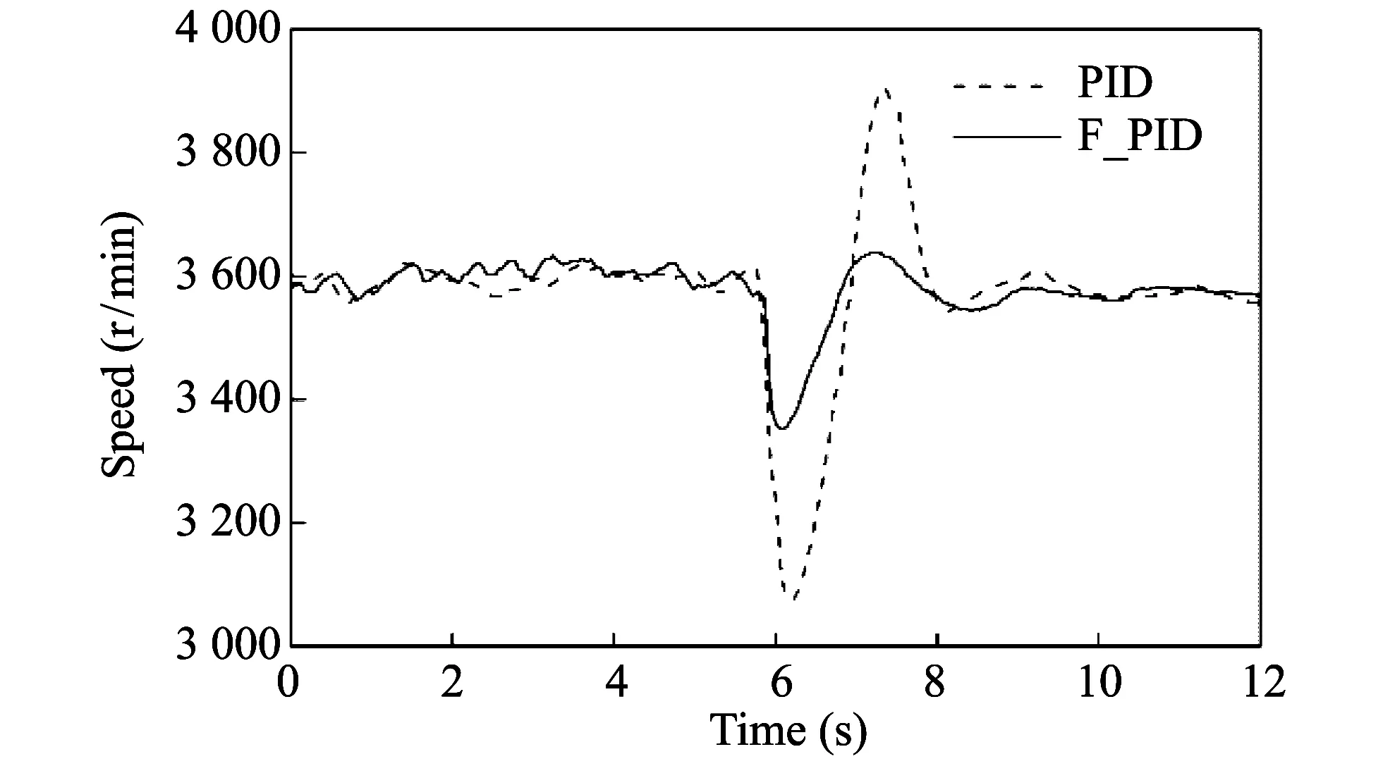
Fig.14 Comparison of speed when 100% load is suddenly applied
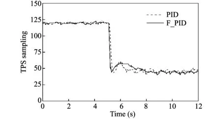
Fig.15 Comparison of TPS when 100% load is suddenly dumped
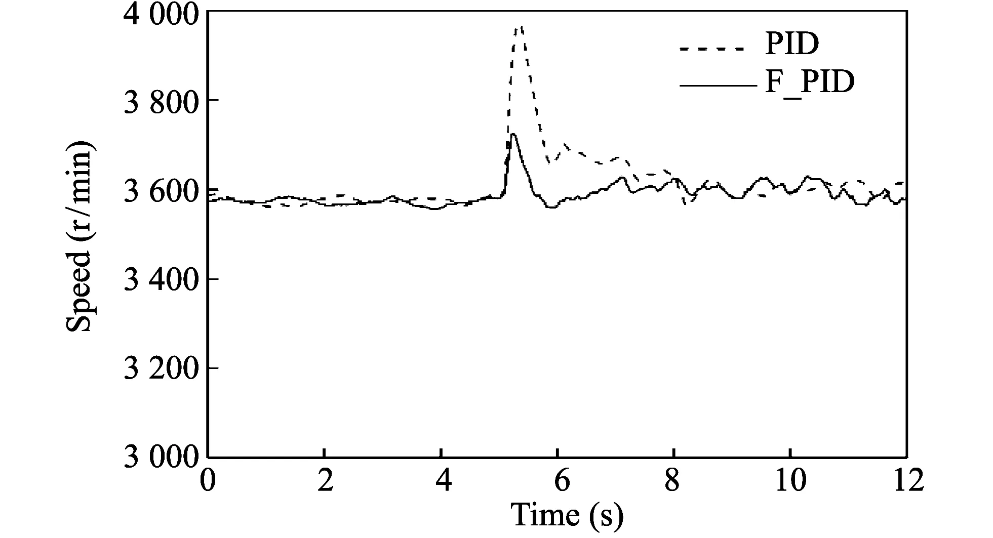
Fig.16 Comparison of speed when 100% load is suddenly dumped
It can be seen that there is little difference between PID control and feed-forward PID control in the steady state and the speed fluctuation is within 50 rpm; when 100% load is suddenly applied, the minimum speed of PID control strategy reaches 3 050 rpm and the maximum value is up to 3 900 rpm, thus the fluctuation range is large. In comparison with Fig.13, throttle action under PID control is slow with serious overshoot, the sampling value is up to 190; when 100% load is suddenly dumped, the maximum speed of PID is up to 3 950 rpm, and TPS overshoot is small but the response is obviously lagged. In the case of feed-forward PID control, when 100% load is suddenly applied, the minimum speed is 3 350 rpm, speed fluctuation is less than 8% of the target speed and fast settling time is about 3.2 s; when 100% load is suddenly dumped, the maximum speed is 3 720 rpm, speed fluctuation is also less than 8% of the target speed and throttle response is quick and settling time is less than 3 s. Thus, the introduction of the feed-forward PID control strategy improves speed controller’s ability significantly in dealing with speed fluctuation in the transient.
Further test was conducted in accordance with the generator test standards. Three groups of experiments were carried out and the results are compared with ISO standard concerning gasoline generator frequency[17], as shown in Table 2.
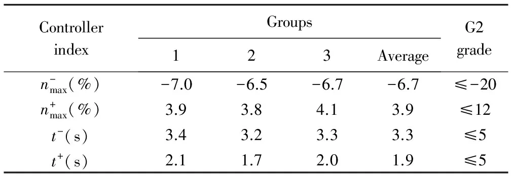
Table 2 Performance index of speed controller
It can be seen from Table 2 that the controller performance is far superior to G2 grade, which proves the designed controller can satisfy the G2 grade of ISO standard and the designed strategies for the controller are effective.
5 Conclusions
1) With speed and throttle position double-loop feedback, the designed controller based on PID algorithm achieves stable control of gasoline generator speed and has high anti-jamming capability.
2) Through bench test, introduction of the feed-forward strategy based on load makes the PID controller have faster response, shorter processing time, smaller overshoot and better dynamic performance.
3) Based on the designed speed controller, the EFI system can be successfully applied to small gasoline generator and substitute the traditional carburetor fuel supply way. Experiment results show that the performance of speed controller can meet G2 grade of ISO standard for gasoline generator.
[1] Tianjin Institute of Internal Combustion Engine. Limits and measurement methods for exhaust pollutants from small spark ignition engines of non-road mobile machinery: GB26133-2010. Beijing: China Environmental Science Press, 2010.
[2] FANG Zu-hua, ZHANG Yong, ZHOU Jin-bao, et al. Emission standards and emission control strategies for small utility gasoline engines. Small Internal Combustion Engine, 2002, 31(4): 34-37.
[3] YANG Yan-xiang, ZHANG Ping, XI Da-guang, et al. Study on technologies with FAI fuel injection system to meet China’s stage III motorcycle emission regulation. Transactions of CSICE, 2009, 27(1): 62-67.
[4] ZHANG Gui-chen. Speed-frequency controller design based on sliding mode for marine diesel generator. In: Proceedings of 2010 Second WRI Global Congress on Intelligent Systems, Wuhan, China, 2010, (2): 31-34.
[5] David J M, John M. Multiple input governor control for a diesel generating set. IEEE Transactions on Energy Conversion, 2008, 23(3): 851 -859.
[6] SHI Yong, QI Zi-da, ZHANG Lian-yu, et al. Application of CMAC neural network coupled with PID controller on speed control of diesel generating set. Transactions of CSICE, 2012, 30 (6): 563-568.
[7] LI Yun-wu, WU Jian-zhong, LIU Yan-bo. Feedforward compensation and PID neural network frequency control for internal combustion engine generating unit. Transactions of CSICE, 2007, 25(4): 379-383.
[8] CHENG Gou-ying. Development of electronic governor for KGEl000Ti petrol generator. Fuzhou: Fujian Agricultural and Forestry University, 2005.
[9] WU Ming-tao. Design and research of gasoline generator adaptive electronic governor. Chongqing: Southwest University, 2013.
[10] YANG Chang-sheng. The research of digital electronic governor for low power gasoline generator. Wuhan: Wuhan University of Technology, 2006.
[11] Duan P, Xie K G. A novel gasoline generators speed governing System based on an improved fuzzy adaptive PID controller. In: Proceedings of the 8th World Congress on Intelligent Control and Automation, Jinan, China, 2010: 4855-4858.
[12] DUAN Qi-chang, LIN Sen, RAO Zhi-bo, et al. The speed governor for gasoline generator based on feedforward compensation sliding mode controller. Control Engineering of China, 2012, 19(6): 1073-1076.
[13] WAN Dong, BAI Fu-qiang, GU Wei-dong, et al. Investigation of air intake characteristics of the fuel injection system of four-stroke motorcycle engine. Small Internal Combustion Engine, 2008, 36(1): 13-18.
[14] YU Yi-long. Study on testing technology and platform for engine management system development. Tianjin: Tianjin University, 2008.
[15] YAO Dong-wei, WU Feng , YANG Zhi-jia, et al. Design of idle speed controller for an SI engine based on incremental digital PID. Journal of Zhejiang University (Engineering Science), 2010, 44 (6): 1122-1126.
[16] Lan Zhou Power and Vehicle Research Institution. Power frequency of gasoline generator set technical qualifications: JB/T1- 0304-2001. Beijing: China Machinery Industry Federation, 2001.
[17] International Organization for Standardization.Reciprocating internal combustion engine driven alternating current generating sets-part5: Generating sets: ISO8528-5. Geneva: ISO, 2013.
基于前馈PID控制的电喷汽油发电机调速器研制
赵自庆1, 刘昌文1, 张 平2
(1. 天津大学 内燃机燃烧学国家重点实验室, 天津 300072; 2. 浙江大学 能源工程系, 杭州 310027)
针对电喷系统在小型汽油发电机组的应用中存在的机械调速方式无法与电喷系统相耦合以及调节滞后、 调节精度差的缺点, 提出了基于负载的前馈PID转速控制策略, 并设计了适用于电喷系统的数字调速器。 详述了调速器的控制策略, 给出了调速器的硬件设计方案以及关键的电机驱动电路、 电流采样电路以及角标捕捉电路, 给出了调速器的软件设计的具体流程, 并结合电喷改装的汽油发电机组, 通过硬件在环、台架实验, 利用工程整定方法对调速器中PID参数进行整定和优化。 实验结果表明, 稳态时, 发电机组转速波动小, 稳定性好; 瞬态时, 调速器动作迅速, 对负荷突变适应力强, 尤其在突加、突卸100%负荷时, 转速波动在8%以内, 稳定时间小于5 s, 调速性能满足ISO标准。
汽油发电机; 数字调速器; 电喷; 前馈; PID控制
ZHAO Zi-qing, LIU Chang-wen, ZHANG Ping. Design of speed controller for electronic fuel injection gasoline generator based on feed-forward PID control. Journal of Measurement Science and Instrumentation, 2015, 6(4): 354-363.
10.3969/j.issn.1674-8042.2015.04.009
ZHAO Zi-qing (zhaoziqing1989@126.com)
1674-8042(2015)04-0354-10 doi: 10.3969/j.issn.1674-8042.2015.04.009
Received date: 2015-08-28
CLD number: TK414.3 Document code: A
猜你喜欢
杂志排行
Journal of Measurement Science and Instrumentation的其它文章
- Sensors layout optimization in explosion overpressure field reconstruction
- Instantaneous rotation speed measurement and error analysis for variable speed hydraulic system
- Experimental study on gas explosion to kill and injury mouse
- Fault diagnosis and analysis of main sea water pump based on vibration monitoring in offshore oil field
- Uncertainty contribution at NIS phototherapy irradiance facility
- Effects of interior ballistic factors on dispersion of central blast tube cluster munitions