Study on high precision cymometer ofmechanical vibration
2015-03-09inghongZHANGTaoHEXinCHENLeiQIU
X ing-hong ZHANG,Tao HE,Xin CHEN,LeiQIU
(Chongqing Key Laboratory of Time-grating Sensing and Advanced Testing Technology,Chongqing University of Technology,Chongqing 400054,China)
Study on high precision cymometer ofmechanical vibration
X ing-hong ZHANG,Tao HE*,Xin CHEN,LeiQIU
(Chongqing Key Laboratory of Time-grating Sensing and Advanced Testing Technology,Chongqing University of Technology,Chongqing 400054,China)
The detection of frequency is one of themost important aspects in the fault diagnosis ofmechanical equipments.The amplitude ofmechanical vibration is small when themechanical equipment is in normal operation.According to the law of conservation of energy,a kind of special vibration measuring sensor is designed which is a variable distance capacitive sensor and it can achievemechanical vibration amplitude amplification.In the hardware processing circuit,a fully differential amplifier circuit is used tomake secondary amplification of electrical signal,and the amplified analog signal is sampled by high resolution ADC.Nanosecond precision time is achieved through software subdivision algorithm,so as to realize the high precision of frequencymeasurement.
Vibrationmeasurement sensor,Capacitor voltage converter,Subdivision algorithms,Precisionmeasurement
Xing-hong ZHANG,Professor.
*Corresponding author:Tao HE,E-mail:hetao814185754@
2012.cqut.edu.cn
1 In troduction
Most of the physical quantities are often converted into time and frequency for precision measurement,because the measurement precision of time and frequency is the highest among all of the physical parameters[1].Mechanical deviceswill vibrate at a certain frequency when working,but the amplitude of vibration is small,which is not convenient to bemeasured directly by sensors.Therefore,the amplitude of mechanical device should be amplified by amplitude amplification device before converting non-electric signal to electric signal.There are two common seen measurementmethods of frequency,such as direct frequencymeasurement and method of cycle test.In the direct frequency measurement method,the measured signal is applied directly to MCU counter,and the
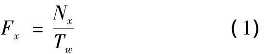
In the cycle testmeasurement,the counter counts reference signal Tsin a cycle of the measured signal(Tx),the relationship between count value Nxand the period of themeasured signal is as follows[6]:

The above traditionalmethods use the countermodule tomeasure frequency,although thismethod can achieve real-time dynamic testing and make the whole frequencymeasurement processmaintain high stability and high accuracy,the ±1 count error is caused by integer count.In this article,the analog electrical signal is sampled by high-resolution A/D and the sampled digital signals are stored in a RAM built in the FPGA.After the data acquisition,the CPU gets the digital signals and calculates the times of passing zerocrossing points in a certain period through zero-comparison method.Then a precision frequency value can be gotten according to the relationship between the time and frequency.MCU counts the pulse signal within the standard time Tw.The relationship between the count value Nxand themeasured signal frequency Fxis as follows[2-5]:
2 The work ing principle of measuring instrument
2.1 The structure of Measuring instrument
As shown in Fig.1,high precision frequencymeasuring instrument consist of vibrationmeasuring sensor,capacitance-voltage converting circuit,signal processing circuit,display device,etc.Vibration measurement sensor is mainly composed of the barrel filled with liquid,lid,and cone gas segment,where the lid is a capacitive sensor.Capacitor voltage converter circuit convert metabolic capacitance into continuous voltage signal.The signal processing circuit ismainly consisted of the amplifier circuit,filter circuit,analog-to-digital converter,field programmable gate array(FPGA)and a central processing unit(CPU).

Fig.1 Diagram o fm easuring instrum ent
2.2 Theworking principle of frequencymeasuring
Vibration measuring sensor can magnify the amplitude of mechanical vibration,and convert amplitude changes to capacitance changes.The amplifier circuit amplifies the voltage signal,and the noise signal in voltage is filtered by filter circuit,the filtered analog signal is shown in figure 2.The times of zero-crossing points(N)is determined by zero-comparisonmethod,zero-crossing points can determine a cycle.Among which,the precise corresponding time of the intermediate zero-crossing points(P1,P2…PN-1)are not necessarily to know,and the corresponding time of P0and PNcan be calculated by software interpolation subdivision algorithm.The time difference between P0and PNis TN,then there is the signal frequency fx:

Where N is integer without error.In Fig.2,the 8 zero-crossing points are used for frequency calculation,the precise corresponding time of intermediate zerocrossing points(P1,P2,P3,P4,P5)are not necessarily to know,only need to ensure they are zero-crossing points or not,according to the positive and negative of sample points next to them.The software interpolation subdivision algorithm can ensure the time t0and t6corresponding to P0and P6,then there is the signal frequency fx:
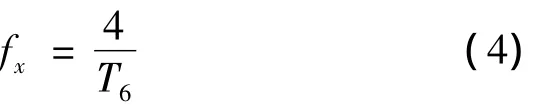
The nanosecond precision measuring of time difference between the starting point(P0)and the end(P6)can be achieved according to the software interpolation subdivision algorithm,which can achieve high-precision frequencymeasurements.

Fig.2 Am p lified and filtered analog signal
2.3 Theworking principle of sensor
In Fig.3,vibrationmeasuring sensor ismainly composed of the barrel filled with liquid,lid,and cone gas segment.The liquid in the barrel iswatermedium which can transmit the vibration characteristics.The top of the lid is a conductivemetal plate,which is the fixed plate of parallel plate capacitor.There are conductive metal thin film underneath fixed polar plate which can vibrate along with the vibration outside,so the cyclical changes ofmechanical parameter are converted to cyclical changes of capacitance.

Fig.3 Vibration sensor
As an amplify device of amplitude,gas section a-bove the liquid is taper structure which the bottom area is larger than the upper area.The lower end of amplifying device also can vibrate along with the liquid when watermedium transmit the vibration characteristic to lower end of amplifying device.Amplitude at the top is greater than the bottom due to positive correlation between the harmonic oscillation energy and its amplitude.According to the law of conservation of energy,amplitude function A(y)is:

Where A1and A2is respectively the amplitude of both ends,c is the propagation velocity of the mechanical wave in the air,f is the vibration frequency,l is the length ofmagnification structure,N is the size ratio of the diameter of the end,that is:

3 Circuit design
The hardware circuit formeasuringmainly includes C/V conversion circuit,amplifier circuit,filter circuit,A/D conversion circuit,FPGA circuit and central processing unit(CPU)circuit,of which C/V conversion circuitmakes changes of capacitance convert to cyclical changes of voltage,and amplifier circuit is full differential amplifier circuit in order to inhibit common-mode signal,the A/D conversion circuit are also use the differential input A/D conversion chip as the core to reduce the analog to digital conversion errors.
3.1 C/V conversion circuit
In order for us to process the signal of sensor,the periodic capacitor variation is converted into periodic voltage variation by CAV424.The CAV424 is an integrated C/V converter and contains the complete signal processing unit for capacitive signals on chip.The CAV424 detects the relative capacitive change of a measuring capacity to a fixed reference capacity[7].Its measuring principle is that change capacitor is measured by bridge consisted of two adjustable current source and two capacitors(C1,Cx):

Where C1is designated as the reference capacitance and Cxis as the measurement signal capacitance.With high common-mode rejection ratio and a high resolution,comparison of the two amplitudes produces a signal which corresponds to the change in capacitance of C1and CXrelative to one another.This difference signal is rectified in an ensuing low pass.The filtered DC signal is transferred to the differential,adjustable output stage.Individual circuit variables,such as filter constants and amplification,can be set with just a few external components,block diagram shown in Fig.4.

Fig.4 C/V converter
3.2 Signal acquisition and processing circuit
Signal acquisition circuit is mainly controlled by FPGA,which the main function is voltage signal acquisition and storage.
As shown in Fig.5,data sampling circuit samples the analog signal and provides the external A/D converter and RAMarea builtwithin the FPGA with clock when CPU issue commands to the FPGA.A/D converter circuit convert analog signal to digital signal under the control of sampling circuit in FPGA and digital signal is stored in the RAM storage area one by one.Cyclone IIFPGA RAMup to 1 Mbits,which store up to 62,500 16 bits data.If 12 bits A/D conversion sampling frequency is set to 1 MHz and 3 waveform data are stored in RAM storage area,lowestmeasured value of frequency measuring instrument is 48 Hz.Highestmeasured value is 30 kHz in order to ensure sampling points up to 32 points.
4 Software design of m easuring system
A flow chart of software design is shown in Fig.6.Data acquisition circuit samples the analog signal un-der the control of a central processing unit(CPU),CPU looks up the number of zero-crossing point(N)based on the data stored in the RAM memory after the sampling is completed and calculates accurately the corresponding time of zero-crossing and end points according to software interpolation algorithm,then calculates the final value of the frequency according to the formula(3),where N is an integer error-free.Nanosecond precision time(TN)measurement is achieved by the software interpolation,which can achieve highprecision frequencymeasurements.

Fig.5 Block diagram o f the signal acquisition and processing
4.1 Determine the numbers of vibration
The analog signal is sampled by data acquisition circuit under the control of the central processing unit(CPU),FPGA sends interruption to CPU after per data acquisition and the interruption signal will drive the CPU operate data analysis and processing program.The program flow chart is shown in Fig.6,where V1and V2in acquisition signalwaveform are two sampling points before and after zero.FPGA sends end command of data sampling after data collection,then CPU reads data temporarily stored in the RAM memory area according to read command.There is supposed to be a zero-crossing point between adjacent sampling pointswhen the property are contrary,meanwhile the zero-crossing counter counts 1 more,and marks the total numbers of zero-crossing points as N.Finally,the vibration frequency is calculated on the basis of software interpolation subdivision algorithm after time calculation.
4.2 Precision determination of vibration time
The CPU sends a read command when data sampling finished and starts to read data in RAM storage area.In order to make further subdivision about the timemeasured by FPGA,and realize the nanosecond precision timemeasurement,the central processing unit(CPU)will analyze and process the receiving data,then it converts the time into frequency according to the time and frequency relation.

Fig.6 So ftw are flow chart
As shown in Fig.7,vibration time consists of T1,nTA/Dand T2,where TA/Dis the sampling period of ADC.There are n sample cycles between P″0and P'6,then n TA/Dis the time between P″0and P″6.

Fig.7 Signal zero-crossing
In a small area of voltage signal,waveform near zero-crossing point is close to the straight line,according to the linear interpolation method,Txcan be expressed as:


As shown in Fig.7,the 8 zero-crossing points are used for frequency calculation,the software interpolation subdivision algorithm can ensure the time t0and t8corresponding to P0and P8.The precise corresponding time of intermediate zero-crossing points(P1,P2,P3,P4,P5)are not necessarily to know,only need to ensure they are zero-crossing points or not,according to the Positive and negative of sample points next to them,then there is the signal frequency fx:

The corresponding time of starting point(P0)and the end(P6)can bemeasured exactly by software interpolation subdivision algorithm,which can realize high precisionmeasurement of frequency.
4.3 The resolution analysis ofmeasurement
Resolution is an important parameter of measuring instruments.When designing the instrument,the analysis of resolution onmeasuring instrument is an indispensable part.The time of vibration mentioned above can be written as:

From the above expression,the time between P0'and P″0is TA/D,the analog signal is sampled by 12 bit ADC,and voltage is V1,V2in P0',P″0point respectively.According to the characteristics of the ADC,the time resolution of zero-crossing point can be expressed as follows:

Assuming that the frequency of transformed signal is 500 kHz and the cycle of signal is2us.The signal amplitude can be divided into 4096 parts because the resolution of the A/D is 12 bits.The ADC chip ADC12DL040,whose sampling frequency can up to40 MHz,is adapted for A/D converting and sampling frequency is set to 32MHz by clock.Therefore,up to 32 points can be sampled during half period.If thewaveform from positive maximum to negative maximum is seen as the linear,it is obviously known that:

During the half period from positive maximum to negative maximum,the curve slope near the zerocrossing point ismuch larger than the slope near the peak,therefore:

Therefore,the resolution of measured time is less than 0.244 ns,so as to realize high precision of frequencymeasurement.
5 Conclusion
In this paper,a kind of frequencymeasuring instrument is designed,which could detect vibration frequency ofmechanical device in real time.The characteristics of designed measuring instrument are as follows:
1)In order to makemechanical parameter converted to voltage signalmore accurately,a amplitude amplifying device of mechanical vibration is designed,which can do the amplification according to the principle of conservation of energy.
2)In the signal processing circuit,the secondary amplification of original signal is conducted by full differential input amplifier circuit,which can greatly restrain the influence of common-mode signals to the measuring result.
3)The real-time detection is achieved because of the hardware circuit based on FPGA and special software interpolation subdivision algorithm,meanwhile the software interpolation subdivision algorithm can achieve 0.244 nanosecond precision timemeasurement,so as to realize high precision of frequency measurement.
Acknow ledgem ents
This paper is supported by the Natural Science Foun-dation of Chongqing(Grant No.cstc2012jjA70004),and the National Natural science Foundation of China(Grant No.51275551).
[1]Li Xiaohui,YANG Xuhai,Liu Ya,ZHANG Huijun,SHI Shaohua.Accurate time and frequencymeasurement[M].Beijing:Science Press,2010.
[2]Chen Tao,XIAO Yani,Yan Rui.Multi-channel precision frequencymeter design based on MCU[J].Gansu Science and Technology,2012,28(19):14-16.
[3]WU Haiming,WANGWei.Design of Equal Precision Cymometer by MCU and FPGA[J].Ordnance Industry Automation,2009,28(3):79-80.
[4]Xiang Cheng,Xia Guorong,Gui Ling.Development of high-speed frequencymeasurement system based on MCU and FPGA [J].Foreign Electronic Measurement Technology,2006,25(12):47-51.
[5]ZHAO Jie.Development of High Frequency Equal Precision Frequency Counter Based on FPGA[J].Journal of Jilin Teachers Institute of Engineering and Technology,2012,28(5):73-77.
[6]Wang Hongli,Cheng Xude,Xu Bing,Zheng Yuan.Design of Intelligent Cymometer Based on Single Chip Microcomputer AT89C51[J].Computer Measurement& Control,2007,15(3):410-412.
[7]CHEN Weimin.An application for measurement of water in oil percentage based on capacitance to voltage signal convert integrate circuit CAV424[J].Journal of China Institute of Metrology,2003,14(2):94-96.
高精度机械振动频率测量仪研究
张兴红,何 涛*,陈 鑫,邱 磊
(重庆理工大学时栅传感及先进检测技术重庆市重点实验室,重庆 400054)
在机械设备的故障诊断中,频率是最重要的检测对象之一。很多机械设备在正常工作时,机械振动幅度较低,为了更方便、快捷地对设备的振动频率进行检测,根据能量守恒定律,设计了一种特殊的振动测量传感器,该传感器可对微弱的机械振动幅度进行机械放大,传感器顶部是一变极距式可变电容,电容的大小会随着电容器下极板的振动而改变,从而把被测非电量的变化转化为电信号的变化。在硬件处理电路中,采用全差分放大电路对电信号进行二次放大,利用模数转换器对二次放大的模拟信号进行采样。通过软件插补细分算法实现纳秒级精度的时间测量,从而实现高精度的频率测量。
振动测量传感器;电容电压转换;细分插补算法;精密测量
10.3969/j.issn.1001-3881.2015.06.009 Document code:A
TG502.14
1 October 2014;revised 24 November 2014;accepted 5 January 2015
猜你喜欢
杂志排行

机床与液压的其它文章
- Time constant of a hydraulic servo valve withdynamic pressure feedback
- Research on fault diagnosis and fault toleranttechnology of IGBT in active power filters
- A new test generation algorithm fornon- robust path delay faults
- Radial fretting character research ofthe shaft-hub of compress impellerbased on virtual orthogonal experiment
- Custom implant design for patients withmandible defects based on rapid prototyping
- Design of car reverse anti- collision warningsystem based on AT89S52