Novel dual-band antenna for multi-mode GNSS applications
2015-01-17HongmeiLiuShaojunFangandZhongbaoWang
Hongmei Liu,Shaojun Fang,and Zhongbao Wang
School of Information Science and Technology,Dalian Maritime University,Dalian 116026,China
Novel dual-band antenna for multi-mode GNSS applications
Hongmei Liu,Shaojun Fang*,and Zhongbao Wang
School of Information Science and Technology,Dalian Maritime University,Dalian 116026,China
A novel dual-band antenna is proposed for mitigating the multi-path interference in the global navigation satellite system (GNSS)applications.The radiation patches consist of a shortedannular-ring reduced-surface-wave(SAR-RSW)element and an inverted-shorted-annular-ring reduced-surface-wave(ISAR-RSW) element.One key feature of the design is the proximity-coupled probe feeds to increase impedance bandwidth.The other is the defected ground structure band rejection flters to suppress the interaction effect between the SAR-RSW and the ISAR-RSW elements.In addition,trans-directional couplers are used to obtain tight coupling.Measurement results indicate that the antenna has a larger than 10 dB return loss bandwidth and a less than 3 dB axial-ratio(AR)bandwidth in the range of(1.164–1.255)GHz and (1.552–1.610)GHz.The gain of the passive antenna in the whole operating band is more than 7 dBi.
active antenna,dual-band antenna,multi-path interference.
1.Introduction
A global positioning system(GPS)receiver measures the apparent transit time of a signal from the GPS satellite to the receiver and,then computes the satellite-to-user range [1,2].The measurements are usually aggravated by time delays,receiver noise,phase-center variation in the antenna,and multi-path interference.Among these factors, multi-path interference is environmentally dependent,diffcult to quantify,and cannot be easily reduced with signal processing techniques.Thus,multi-path interference has remained one of the limiting factors in the case of modern high-precision GPS applications[3–5].
Multi-path interference is the result of line-of-sight signal replicas coming towards the antenna after refection and diffraction from the surrounding environment. One common GPS antenna solution to mitigate multi-path interference is microstrip patch antennas mounted on a choke-ring ground plane[6,7],but they are usually bulky and diffcult to accommodate.In[8],a GPS antenna based on an array of coupled spiral slots in a pinwheel type confguration was introduced,which decreases the weight and bulk associated with the choke-ring design.However, the gain of the antenna is not high enough.The reducedsurface-wave(RSW)antenna[9,10],which was proposed by Boccia et al.,reveals better radiation performance while being less cost and more compact than the choke-ring design,and proves a higher gain than the pinwheel antenna design.In[11–13],the shorted-annular-ring(SAR)-RSW and inverted-shorted-annular-ring(ISAR)-RSW antennas for GPS applications were also proposed.They provide similar or better performances while beingat least an order of magnitude smaller in terms of volume and weight than the choke-ring design,and are easier to manufacture than the pinwheel design.
With the introduction of GPS,GLONASS and Galileo, several more frequencies will be available.Thus multimode global navigation satellite system(GNSS)antennas with reduced multi-path interference are necessary.Although antennas for GNSS applications have been proposed before[14–17],they are usually bulky,and have a small antenna gain.
In this paper,a novel dual-band active antenna with 58 MHz bandwidth at band L1 and 91 MHz at band L2/L5 is proposed for mitigating the multi-path interference in the GNSS applications.With the properties of reduced horizon and increased cross polarization ratio levels, good circular polarization characteristics,and similar performance at band L1/L2/L5,the proposed active antenna shows promise for dual-band high-precision GNSS applications.
2.Dual-band active RSW antenna
2.1RSW antenna design
As shown in Fig.1,the RSW antenna is fabricated on theF4B substrate with a dielectric constant of 2.65,a loss tangent of 0.001 and a height h3of 3 mm.With the formula from[11],aRand bRof the SAR-RSW element are calculated to be 28.1 mm and 55.7 mm,respectively.The outer andinner radius(aIandbI)of the ISAR-RSW element are found to be 127.5 mm and 74 mm[12],respectively.The grounded probes with a diameter of 0.65 mm are used for the short-circuit boundary of the SAR-RSW and the ISARRSW elements.They are spaced 5°and 10°apart,respectively.To broaden the operation band,an air gap with a height h2of 6 mm is added.
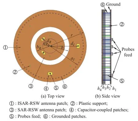
Fig.1 Geometry of the RSW antenna
A thicker substrate and a bigger air gap imply longer feed probes with more inductance,which will lead to poor impedance matching.To solve the problem,rectangle patches acted as proximity-coupled probe feeds are used to induce capacitance and compensate for the increased inductance.The rectangle patches are fabricated on the same F4B substrate as above except for the thickness(h4= 1 mm).
After optimization using the Ansoft HFSS 3D EM simulator,the dimensions of the SAR-RSW and the ISAR-RSW elements are aR=28.1mm,bR=56mm,aI=127.5mm and bI=74 mm.The SAR-RSW element is fed at its 50 Ω match point corresponding to dR=38 mm with equal rectangle patches of 2.6 mm×10 mm.Another two rectangle patches with equal dimensions of 6 mm×8 mm are located at dI=108 mm to feed the ISAR-RSW element.
Fig.2 shows the impedance response of the RSW antenna.It can be seen that the ISAR-RSW and the SARRSW elements have a relatively good impedance matching from 1.164 GHz to 1.255 GHz and from 1.552 GHz to 1.610 GHz,respectively.It is found in Fig.2 that there is a slight overlap between the TM011mode of the SARRSW element and the TM031mode of the ISAR-RSW element.This interaction effect will have a bad infuence on designing a single-input feed network capable of simultaneously feeding the SAR-RSW and the ISAR-RSW elements.

Fig.2 Simulated impedance responses of the RSW antenna
2.2Feed network design
The feed network,as shown in Fig.3,is also fabricated on the same F4B substrate as above except for the thickness(h1=1.5mm).It is composed of two trans-directional (TRD)couplers and four defected ground structure(DGS) band rejection flters.
To obtain tight coupling,TRD couplers consisted of periodically loaded coupled lines are used to feed the SARRSW and the ISAR-RSW elements,respectively.According to the analysis of[18],with certain values of the electrical length 30°and the number 3 of the loaded coupled line element,the even-and odd-mode characteristic impedances of the parallel coupled lines are calculated to be 120.9 Ω and 77.2 Ω,respectively.C1=2.2 pF,C2= 3 pF.Finally,the dimensions of the parallel coupled lines are determined:w1=1.3 mm,s1=1 mm,l1=7.9 mm, w2=1.3 mm,s2=1 mm and l2=6 mm.
To suppress the interaction effect between the ISARRSW and the SAR-RSW elements,higher band DGS bandrejection flters are connected to the output ports of the lower band TRD coupler with dimensions of w=4.2 mm, d1=0.4 mm,d2=0.4 mm,l3=24.6 mm,l4=6 mm and l5=6 mm.In addition,a same DGS band rejection flter located at the input port of the lower band TRD coupler is associated with a lower band flter to combine the signals receiving from the SAR-RSW and the ISAR-RSW elements.The dimensions of the lower band flter are:w= 4.2 mm,d3=0.4 mm,d4=0.6 mm,l6=24.6 mm,l7= 7.6 mm and l8=7.6 mm.

Fig.3 Geometry of the feed network
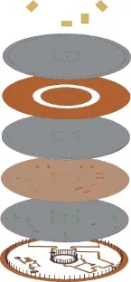
Fig.4 Exploded view of the proposed active RSW antenna
2.3RSW antennas integration with the feed network
Fig.4 shows an exploded view of the proposed dualband active antenna.It is composed of three layers.The proximity-coupled probe feed patches are etched on the top layer.The radiation patches are located on the middle layer. On the bottom layer,there is the feed network.The radiation patches of the middle layer are fed by four rectangle patches on the top layer,and the four rectangle patches are connected to two 3 dB TRD couplers via probes.The ground of the feed network is also acted as the ground of the RSW antenna.To keep a well stability,nine plastic supports with a diameter of 1.5 mm are added to the antenna. The prototype of the proposed active antenna with a diameter of 140 mm is shown in Fig.5.In the confguration,a two-stage low-noise amplifer (LNA)added with RF/DC collinear technology is designed to amplify the weak signals received by the proposed passive antenna.The measured bandwidth of the LNA under the criteria that|S11|< –11 dB and|S22|<–14 dB is from 1.00 GHz to 1.70 GHz.Over the frequency range of (1.00–1.65)GHz,the LNA has a measured gain of about 29 dB and a measured noise factor of(0.8±0.05)dB.

Fig.5 Prototype of the proposed active RSW antenna
3.Experimental results and analysis
The S-parameters of the feed network and the passive antenna are measured by an Agilent N5230A vector network analyzer.The simulated and measured return loss results of the feed network are given in Fig.6.A larger than 10 dB measured return loss is obtained over the desired(1.164–1.225)GHz and(1.552–1.610)GHz frequency range. Figs.7 and 8 show the insertion losses and phase differences of the feed network,respectively.The port numbers in Fig.7 are corresponding to the port numbers shown in Fig.3,namely,port9 is the output port of the feed network, port3 and port4 are the feeding ports for the ISAR-RSW element,and port7 and port8 are the feeding ports for the SAR-RSW element.It is observed that the feed network delivered balanced output ports power distribution(3.5±0.5)dB and consistent(90°±0.5°)output ports phase differences in the range of(1.164–1.225)GHz and(1.552–1.610)GHz.The measured return loss of the proposed passive antenna is more than 10 dB from 1.164 GHz to 1.225GHz and from 1.552GHz to 1.610GHz,as shown in Fig.9.
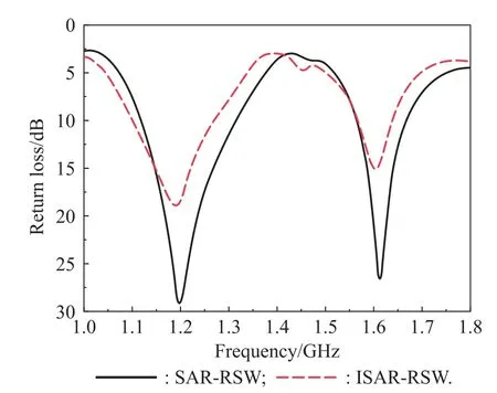
Fig.6 Simulated and measured return losses of the feed network
The radiation characteristics of the proposed passive antenna are measured in an anechoic chamber,and a comparison between the simulated and the measured results are fgured,as listed in Figs.10,11 and 12.In the range of(1.160–1.260)GHz and(1.540–1.610)GHz,the passive antenna has a measured axial-ratio(AR)of less than 3 dB in the boresight direction(θ=0°)and a gain-level of more than 7 dBi,as shown in Fig.10.

Fig.7 Simulated and measured insertion losses of the feed network

Fig.8 Simulated and measured phase differences of the feed network
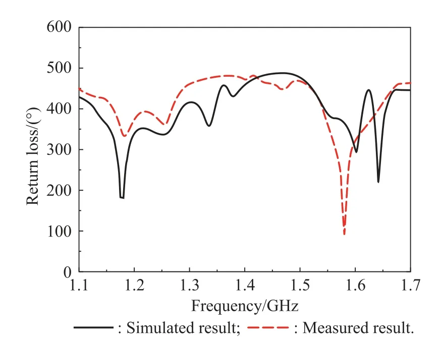
Fig.9 Simulated and measured return loss of the passive antenna

Fig.10 AR and gain performances of the passive antenna
Due to the fabrication error,there is a discrepancy between the simulated and the measured results,and the measured AR is better than the simulated one.Fig.11 shows the simulated and measured radiation patterns for the proposed passive antenna at 1.58GHz.The right-hand circular polarization(RHCP)felds are stronger than the left-hand circular polarization(LHCP)felds by more than 21 dB in the boresight direction(θ=0°).In the elevation angle of 0°to 5°,the RHCP gain is less than–17 dBi and the LHCP gainis less than–12dBi.For the passive antenna at 1.21GHz,good radiation characteristics are also observed, as shown in Fig.12.The passive antenna has an axial cross polarization ratio of more than 18 dB.In the elevation angle of 0°to 5°,the RHCP gain is less than–15 dBi and the LHCP gain is less than–12 dBi.

Fig.11 Radiation patterns of the passive antenna at 1.58 GHz
As we know,the multi-path interference is mainly caused by the frst refection and diffraction of the signal. Through the frst refection and diffraction,the signals are easily to be changed from the RHCP to the LHCP.Thus,a high cross polarization ratio is needed to reject the LHCP signal.When the antenna is applied on shipboard,the refection and diffraction signals often come from the low elevation direction,hence antennas with a small low elevation gain are needed.The radiation characteristics of the proposed antenna listed above can ensure the ability to reject multi-path interference by polarization and low level horizon.

Fig.12 Radiation patterns of the passive antenna at 1.21 GHz
4.Validation in GNSS
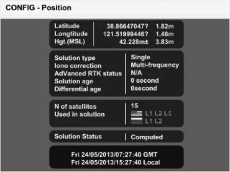
Fig.13 Measured location result of the proposed active antenna
To verify the operation of the RSW active antenna in GNSS applications,the precision measurement is carried out.The proposed dual-band active antenna,the receiver and a computer are connected together on the roof of a building for test.The position result of the proposed antenna can be seen on the computer screen,as shown in Fig.13.To demonstrate the proposed antenna,a comparison is made between the proposed antenna and a pinwheel antenna labeled GPS-704X which is manufactured by NovAtelcompany.The pinwheel antenna is measured under the same condition with the proposed antenna.The location result is shown in Fig.14.It can be found from Fig.13 and Fig.14 that the proposed dual band active antenna can track 15 satellites with a latitude precision of±1.82 m and a longitude precision of±1.48 m,while the GPS-704X pinwheel antenna tracks 13 satellites with a latitude and a longitude error of 2.51 m and 2.01 m,respectively. Therefore,the performance of the proposed antenna is better than that of the GPS-704X pinwheel antenna.

Fig.14 Measured location result of the NovAtel’s GPS-704X antenna
5.Conclusions
A novel dual-band active RSW antenna for mitigating the multi-path interference in GNSS applications is designed,fabricated and experimentally tested.The experimental results show that the proposed passive antenna has an impedance bandwidth(return loss>10 dB)of(1.164–1.255)GHz and(1.552–1.610)GHz,a 3 dB AR bandwidth of(1.160–1.260)GHz and(1.540–1.610)GHz,a larger than 7 dBi passive gain in the whole operating band, and a less than–15 dBi RHCP gain in 0°−5°elevation. The proposed antenna can operate in the GPS/GLONASS/ Galileo systems with reduced multi-path interference and a high gain.The active antenna is also validated in GNSS applications,and the signal reception performance and cost are superior to the NovAtel’s GPS-704X pinwheel antenna.Therefore,the proposed antenna can be a suitable candidate for GNSS applications.
[1]E.D.Kaplan.Understanding GPS principles and applications. New York:Artech,1996.
[2]S.K.Zhang,H.B.Wang,J.Yang,et al.GPS short-delay multipath estimation and mitigation based on least square method. Journal of Systems Engineering and Electronics,2009,20(5): 954–961.
[3]F.S.Scappuzzo,S.N.Makarov.A low-maltipath wideband GPS antenna with cutoff or non-cutoff corrugated ground plane.IEEE Tran.on Antennas and Propagation,2009,57(1): 33–46.
[4]M.Chen,C.C.Chen.A compact dual-band GPS antenna design.IEEE Antennas and Wireless Propagation Letters,2013, 12:245–248.
[5]F.Bilitti,C.Vegni.Design of high-performing microstrip receiving GPS antennas with multiple feeds.IEEE Antennas and Wireless Propagation Letters,2010,9:248–251.
[6]E.C.Wang,Z.P.Wang,Z.Chang.A wideband antenna for global navigation satellite system with reduced multipath effect.IEEE Antennas and Wireless Propagation Letters,2013, 12:124–127.
[7]J.M.Tranquilla,J.P.Cam,H.M.Al-Rizzo.Analysis of a choke ring ground plane for multipath control in global positioning system(GPS)applications.IEEE Trans.on Antennas and Propagation,1994,42(7):905–911.
[8]NovAtel.GPS-704X antenna design and performance. http://webone.novatel.ca/assets/Documents/Papers/GPS-704x-WhitePaper.pdf.
[9]L.Boccia,G.Amendola,G.D.Massa,et al.Shorted annular patch antennas for multipath rejection in GPS-based attitude determination systems.Microwave and Optical Technology Letters,2001,28(1):47–50.
[10]L.Boccia,G.Amendola,G.D.Massa.A shorted elliptical patch antenna for GPS applications.IEEE Antennas and Wireless Propagation Letters,2003,2:6–8.
[11]L.I.Basilio,J.T.Williams,D.R.Jackson,et al.A comparative study for a new GPS reduced-surface-wave antenna.IEEE Antennas and Wireless Propagation Letters,2005,4:233–236.
[12]L.I.Basilio,J.T.Williams,D.R.Jackson,et al.Characteristics of an inverted-shorted-annular-ring reduced-surfacewave antenna.IEEE Antennas and Wireless Propagation Letters,2008,7:123–126.
[13]L.I.Basilio,R.L.Chen,J.T.Williams,et al.A new planar dual-band GPS antenna designed for reduced susceptibility to low-angle multipath.IEEE Trans.on Antennas and Propagation,2007,55(8):2358–2366.
[14]D.Li,P.Guo,Q.Dai,et al.Broadband capacitively coupled stacked patch antenna for GNSS applications.IEEE Antennas and Wireless Propagation Letters,2012,11:701–704.
[15]J.X.Li,H.Y.Shi,H.Li,et al.Quad-band probe-fed stacked annular patch antenna for GNSS applications.IEEE Antennas and Wireless Propagation Letters,2014,13:372–375.
[16]M.Maqssod,S.Gao,T.W.C.Brown,et al.A compact multipath mitigating ground plane for multiband GNSS antennas.IEEE Trans.on Antennas and Propagation,2013,61(5): 2775–2782.
[17]X.Li,L.Yang,M.Wang,et al.Wideband shorted annular stacked patch antenna for global navigation satellite system application with compact size and broad beamwidth characteristics.Progress in Electromagnetics Research C,2013,35: 123–134.
[18]C.I.Shie,J.C.Cheng,S.C.Chou,et al.Transdirectional coupled-line couplers implemented by periodical shunt capacitors.IEEE Trans.on Microwave Theory and Techniques,2009, 57(12):1981–1988.
Biographies

Hongmei Liu was born in 1989.She received her B.S.degree in communication engineering from Dalian Maritime University,in 2011,and she is currently working toward her Ph.D.degree at Dalian Maritime University.Her current research interests include antennas,passive RF components and active circuits.
E-mail:lhm323@dlmu.edu.cn

Shaojun Fang was born in 1957.He received his Ph.D.degree in communication and information systems from Dalian Maritime University,in 2001. He is currently a head professor with the Information Science and Technology Department.His recent research interests include antennas and computational electromagnetics.
E-mail:fangshj@dlmu.edu.cn

Zhongbao Wang was born in 1983.He received his Ph.D.degree in communication engineering from Dalian Maritime University,in 2012.He is currently a lecturer with the Department of Information Science and Technology,Dalian Maritime University. His current research interests include antennas and passive RF components.
E-mail:wangzb@dlmu.edu.cn
10.1109/JSEE.2015.00003
Manuscript received April 28,2014.
*Corresponding author.
This work was supported by the National Natural Science Foundation of China(61071044),the Traffc Applied Basic Research Project of the Ministry of Transport of China(2010-329-225-030),the Doctor Startup Foundation of Liaoning Province(20141103),the Scientifc Research Project of the Department of Education of Liaoning Province (L2013196),and the Fundamental Research Funds for the Central Universities(2014YB05).
杂志排行

Journal of Systems Engineering and Electronics的其它文章
- Dynamic channel reservation scheme based on priorities in LEO satellite systems
- Adaptive beamforming and phase bias compensation for GNSS receiver
- Nonparametric TOA estimators for low-resolution IR-UWB digital receiver
- Effcient hybrid method for time reversal superresolution imaging
- Adaptive detection in the presence of signal mismatch
- Estimating DOA and polarization with spatially spread loop and dipole pair array