Effects of Shape and Quantity of Helical Baffle on the Shell-side Heat Transfer and Flow Performance of Heat Exchangers*
2014-07-24DUWenjing杜文静WANGHongfu王红福andCHENGLin
DU Wenjing (杜文静), WANG Hongfu (王红福) and CHENG Lin (程 林)
Institute of Thermal Science & Technology, Shandong University, Jinan 250061, China
Effects of Shape and Quantity of Helical Baffle on the Shell-side Heat Transfer and Flow Performance of Heat Exchangers*
DU Wenjing (杜文静), WANG Hongfu (王红福) and CHENG Lin (程 林)**
Institute of Thermal Science & Technology, Shandong University, Jinan 250061, China
Shape and quantity of helical baffles have great impact on the shell-side performance of helical baffled heat exchangers (HBHE). In this work, three physical models of HBHE with baffles of different shape (trisection, quadrant and sextant sector) were investigated. Numerical simulations were performed on HBHE at three helix angles (10°, 25° and 40°) by the software ANSYS CFX. Analyses of numerical results indicate that the sextant HBHE shows relatively better fluid flow performance because the leakage flow in the triangle area is evidently reduced and the fluid streamline appears much closer to an ideal spiral flow, while the trisection and quadrant HBHE show more scattered and disordered streamline distributions. The convective heat transfer coefficient and pressure drop in three types of HBHE were presented. Further investigations on the shell side performance with different helical baffles were implemented by the field synergy theory. Both theoretical and numerical analyses gave support on the relations between helical baffle shape and shell-side performance. This paper may provide useful reference for the selection of baffle shape and quantity in HBHE.
helical baffled heat exchanger, trisection, quadrant, sextant, field synergy principle
1 INTRODUCTION
Shell-and-tube heat exchangers (STHE) are widely used in petrochemical industry, power generation, food industry and waste heat recovery due to its lower production cost, more convenient cleaning and more flexible adaptability compared with other heat exchangers. More than 35%-40% of heat exchangers are the shell-and-tube ones in the world [1-3]. However, traditional STHEs with segmental baffles show low heat transfer efficiency and large pressure drop [4-6]. In 1990, a novel kind of STHE with the helical baffle was proposed by Lutcha and Nemcansky aiming to improve the shell side heat transfer performance [7]. If comparison is made between the segmental baffle and the helical one in STHEs, the latter exhibits many merits, such as less shell-side pressure drop, better heat transfer performance, less fouling and less fluid induced vibration [8-11]. In recent years, many investigations have been performed on helical baffled heat exchangers (HBHE). Jafari Nasr and Shafeghat [12] studied the HBHE with quarter sectors designed by the rapid design algorithm, and found that helical baffles at 40° had better performance compared with others. Zhang et al. [13] performed experimental investigations on STHEs with helical baffles and segmental baffles. They concluded that the heat exchangers with helical baffles performed much better than the heat exchanger with segmental baffles. Taher et al. [14] studied the impact of baffle spacing on the performance of HBHE. The results of simulation indicated that heat transfer per unit area and pressure gradient decreased with an increasing baffle space. Wang et al. [15] demonstrated that triangle choke plates between adjacent quadrant helical baffles reduced the triangle leakage flow, but the comprehensive performance in the shell side was decreased. The above-mentioned helical baffles are in the shape of non-continuous approximate helicoids. They are usually composed of quadrant sector baffles overlapped end to end. It was reported that Dong et al. [16] and Wang et al. [17] proposed a novel trisection helical baffle which was suitable for a regular triangle tube layout and the corresponding heat exchanger was much compact. Chen et al. [18] performed numerical simulation on the flow field of trisection HBHE and their results demonstrated that the circumferential overlap between trisection helical baffles restricted the short circuit of flow and the shell-side flow pattern was much close to the “plug flow”. Cao [19] put forward a new STHE with sextant helical baffles, and the related results showed that the shell-side dead region and leakage from the triangle zone were obviously reduced and radial velocity distribution became even uniform.
In HBHE, the shape and quantity of helical baffles have an obvious effect on the shell-side performance. However, there is no literature record which makes detailed comparison and researches in this aspect. Therefore, in this paper the method of numerical simulation was applied to investigate the effect of three kinds of helical baffles on heat exchanger performance. Three-dimensional physical models of HBHE were first established by the software Pro/E. Then the software ANSYS CFX was used to calculate the fluid flow characteristics and heat transfer performance in the entire three-dimensional shell space. The mechanism of flow resistance reduction and heat transfer enhancement was analyzed. This work may provide useful information for the selection of shape and quantity of helical baffles.

Table 1 Geometrical parameters of investigated heat exchangers
2 COMPUTATIONAL MODEL
2.1 Physical models
In this paper, the physical models include three kinds of helical baffle, namely the trisection, the quadrant and the sextant ones. Comparison is made on these three baffles at the helix angles of 10°, 25° and 40° respectively. The conduction oil was selected as shell-side fluid. The geometric parameters of heat exchangers are determined based on the Chinese National Standard GB151-1999 on tubular heat exchangers, which are listed in both Tables 1 and 2. The computational domain is shown in Fig. 1.

Table 2 Geometrical parameters of helical baffles

Figure 1 Computational domain of physical models
2.2 Turbulent model and governing equation
The fluid flow in the HBHE is extremely complicated and three-dimensional, whose characteristics are mainly summarized as strong transient, rotational and anisotropic. RNG k-ε [20, 21] turbulent model based on the renormalization group technique is an improvement from the standard k-ε turbulent model. It takes the impact of both low and high Reynolds number into consideration, and it performs better in the streamline curvature, vortex and rotational flow computation. Therefore, the RNG k-ε turbulent model is selected in this work.
The steady fluid flow is dominated by the physical conservation laws, and the fundamental conservation laws contain mass conversation, energy conversation and momentum conservation. The above equations can be described using a universal governing equation:

where φ presents different physical variables, including the velocity components u, v, w, temperature T, turbulence kinetic energy k and turbulence kinetic energy dissipation ε, while Γφstands for the diffusion coefficient and Sφrepresents the source term [22].
2.3 Assumptions and boundary conditions
The following assumptions are used in the present numerical simulation. Conduction oil, the shell-side working fluid, is incompressible. Related physical properties are density ρ=842 kg·m−3, thermal conductivity λ=0.1 W·m−1·K−1, and specific heat capacity cp=2093 J·kg−1·K−1. The fluid flow is turbulent and heat transfer in steady state. As the oil viscosity changes greatly with temperature, a quadratic function of temperature, Eq. (2), is used to calculate the value of oil dynamic viscosity, where T denotes the oil absolute temperature in K:

Other parameters of conduction oil are taken as constant. Ignore the effects of gravity and the buoyancy induced by the temperature difference, and the heat effects of fluid viscous dissipation. The leakage flow between tube and baffles and that between baffles and the shell are neglected.
The boundary conditions are as follows: (1) Entrance velocity boundary condition is applied on the shell-side inlet section; the mass flow rate is set as the control variable and the fluid temperature is 350 K. (2) Exit pressure boundary condition is used on the outletsection, and the average static pressure is set as 0 Pa. (3) Shell wall and baffle surfaces are defined as non-slip and adiabatic, and surface temperature of the tube is set as a constant of 310 K.
2.4 Grid generation and independence verification
Owing to the shell side complicated structure of HBHE, unstructured grid with tetrahedral and pyramidal cells is used. The grid is iterated three times according to the value of temperature gradient and velocity gradient based on the grid adaptive technique. For the gird independence verification, the computational domain of sextant HBHE with 25° helix angle is meshed into different number of cells: 4.6, 6.2, 8.7, 11.0 and 13.1 million. Numerical simulation is performed on the HBHE with different grids under the same working conditions. The shell side heat flux versus the grid quantity is shown in Fig. 2, and we can find that the differences among the last three groups are all less than 2% and within the scope of calculation error, which means the change of grid fineness has little impact on the computing results when the grid amount reaches 8.7 million. Therefore, the 8.7 million grids are selected by considering both the computation accuracy and the efficiency. The convergence criterion for residual monitoring is assumed to be 1.0×10⁻⁵for related equations.

Figure 2 Shell-side heat fluxes versus grid quantities (sextant HBHE, β=25°, Vs≈1.5 m·s−1, inlet mass flow rate Ms=5 kg·s−1)
2.5 Models validation
To validate the above-mentioned computational method, the middle-overlapped HBHE with 40° helical angle presented in Ref. [13] is simulated. Comparison is made with the experimental data in Ref. [13]. Figs. 3 and 4 indicate that the discrepancy between the numerical simulation results and experimental ones is in the range of 4.5% to 10.1% for convective heat transfer coefficient and in the range of 5.3% to 14.4% for pressure drop. The difference stays in an acceptable range and the variation trends are also consistent, which shows the reliability of the numerical simulation in this paper. Besides some unavoidable measurement errors, these discrepancies come from the fact that the physical model is simplified. The baffles and shell wall are simplified as adiabatic and the tube is defined as constant surface temperature, which is partially different from the practical condition.

Figure 3 Comparison of shell-side convective heat transfer coefficient between experiment data and simulation data (middle-overlapped HBHE, β=40°)

Figure 4 Comparison of pressure drop between experiment data and simulation data (middle-overlapped HBHE, β=40°)
3 RESULTS AND DISCUSSION
3.1 Streamline distribution
Characteristic velocity Vsis the mean velocity of the fluid on the minimum shell-side flow section. When the helix angle β is set as 25° and the characteristic velocity Vsis around 1.5 m·s−1, the shell-side streamline distributions with different helical baffles are shown in Fig. 5. In Fig. 5 (a), the short-circuit flow is evidenced by those streamlines which are located on the central region and segregated from the major spiral flow. The short-circuit flow is shown with streamlines which pass through the triangular gap between adjacent plates. In Fig. 5 (a), fluid flow seriously deviates from an ideal spiral flow. Streamline distribution is scattered and disordered. A lot of short-circuits exist in the central tube regions and separated from the spiral flow. In Fig. 5 (b) shell-side fluid flow condition formed by the quadrant helical baffles is improved and behaves as an approximate spiral flow. Besides, the triangle leakage flow is decreased. Fluid flow in Fig. 5 (c), which is generated by the sextant helical baffles, actsas a smooth and steady continuous spiral flow. Benefitted from the overlapped part between adjacent helical plates, the short-circuit flow decreases evidently and major fluid joins the rotating flow.

Figure 5 Shell-side streamline distributions of heat exchangers with different helical baffles (β=25°, Vs≈1.5 m·s−1)
3.2 Velocity distribution
Figure 6 illustrates the percentage distribution of shell-side velocity V when the characteristic velocity Vsis around 1.5 m·s−1. In the y-axis, Mvis used to describe the mass flow rate of the fluid whose shell-side velocity is equal to V and Msis the total shell-side mass flow rate. As shown in Fig. 6 where 1/3, 1/4 and 1/6 represent trisection, quadrant and sextant HBHE respectively, the average velocity increases with the increase of helical angle β, and the overall distribution becomes much concentrated and consistent. The stability of fluid flow is gradually improved. Comparing the three different shaped HBHE with the same helical angle, the average velocity for the sextant baffle is relatively larger, and simultaneously the uniformity of velocity distribution and flow stability are much better. The region with relatively small flow rate is generally the one with poor local heat transfer performance. For the trisection, quadrant and sextant HBHEs, the percentages of V<0.3 m·s−1are 12.2%, 10.6% and 8.1% respectively when β=25°, and the percentages are 8.2%, 7.9% and 6.6% respectively when β=40°. Therefore, the shell-side fluid flow conditions are gradually improved when the helical angle increases.
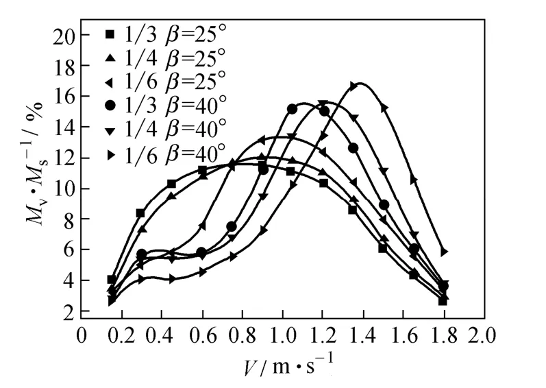
Figure 6 Percentage distribution of shell-side velocity (β=25°, 40°, Vs≈1.5 m·s−1)
Figure 7 depicts the velocity distribution on the shell cross section on the overlapped joints between adjacent baffle plates when Vs≈1.5 m·s−1and β=25°. It is observed fluid is rotating on the section and is inclined crossing-flow the tube bundle, which can damage the boundary layer around tubes and enhance heat transfer. The top of the section area is a triangular area; short circuit flow is formed on the gap, resulting a relatively high axial flow rate in the shell central region. Meanwhile the leakage flow is in the opposite direction of the mainstream, which will form a large pressure loss at the intersection area. Fig. 7 (a) shows the most serious leakage flow in the upper-left area because of the trisection helical baffle. Compared with Fig. 7 (a), the quadrant helical baffle in Fig. 7 (b) shows a better flow condition and the entire shell velocity distributions is uniformed, but the leakage flow at the triangle area is still present. The sextant helical baffle in Fig. 7 (c) behaves the most inconspicuous leakage flow, and the velocity distribution tends to be uniform, without flow dead zone, leading to better heat transfer performance.

Figure 7 Velocity distributions in the cross section of HBHE (β=25°, Vs≈1.5 m·s−1)

Figure 8 Velocity distributions in the longitudinal section (β=25°, Vs≈1.5 m·s−1)
Figure 8 is the longitudinal velocity distribution in the shell side section when Vs≈1.5 m·s−1and β=25°. The fluid flow is angled to the tubes on the vertical section and the direction is consistent with that of the whole spiral flow. Leakage flow is formed when fluid flow through the gaps between adjacent plates. The trisection sector plate has the maximal gaps and the most obvious leakage. The leakage decreases between the quadrant sector plates. The overlapped part between adjacent sextant plates makes the minimal gaps and leakage, and it can bring backflow and vortex. The velocity vector distribution shows that the fluid flow is divided into several branches between the trisection sector plates. Besides, the direction of partial branches conflicts with that of main stream. The fluid flow is more concentrating between thequadrant sector plates and it has more consistent vector direction. But there is a larger velocity gradient from the shell center to the circumference. In other words, the velocity distribution is non-uniform. In HBHE with the sextant baffle, the overall fluid flow is obviously ordered and consistent. The entire velocity gradient is decreased, which behaves a good uniformity and spiral flow effect.
3.3 Shell-side heat transfer performance
Figure 9 is the variation of the convective heat transfer coefficient hsin HBHE with the characteristic velocity Vs. Results show that convective heat transfer coefficient increases with the increase of the helical angle. The reason accounting for this is mainly that fluid flow velocity is improved when the helix angle is increased, and simultaneously much uniform velocity distribution is achieved. If the helical angle and the characteristic velocity are kept as constants, the convective heat transfer coefficient of the sextant sector plate is the maximum and that of the trisection plate is the minimum. The velocity distribution characteristics provide support for these phenomena.
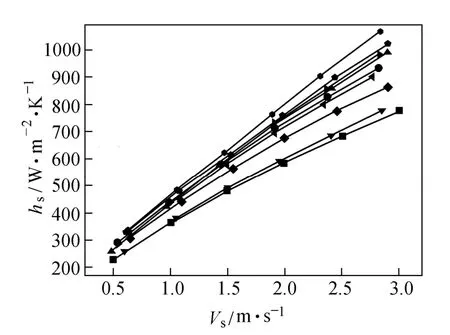
Figure 9 Shell side convective heat transfer coefficient hsversus Vs(β=10°, 25°, 40°)
We use Fig. 10 to obtain information on heat transfer rate distributions in different tubes. Qδis used to describe the heat flux per area of tubes whose axes are at different radial positions. The vertical axis in Fig. 10 denotes the ratio of heat flux Qδin different radial positions and heat transfer rate Qδ=0of the central tube with Vs≈1.5 m·s−1. Abscissa δ is the dimensionless length, the ratio between the tube distance from central axis and the shell inner radius. Due to the effect of leakage flow in the triangle center, velocity in the central area is relatively larger than that of others. Hence heat transfer rate on the tube surface from the central to the periphery reduces gradually. With the increase of helical angle β, fluid flow rate on the shell side are gradually uniformed and difference of Qδis in a reduction tendency. Benefitted from its velocity distribution characteristics, the uniformity of Qδ/Qδ=0in the sextant sector plate is much better than that of the other two.

Figure 10 Radial distribution of heat transfer rate on tube surfaces (β=25°, Vs≈1.5 m·s−1)
3.4 Shell-side fluid flow pressure drop
Pressure drop in shell side, determining the consumption of pump power, is hereafter one of the most important factors for designing and rating heat exchangers. Fig. 11 shows the variation of the pressure drop per unit length of tube versus Vs. It is clear that shell side pressure drop ΔPsincreases with the increasing characteristic velocity and such increment is much obvious with relatively large Vs. When the helical angle decreases, the shell side pressure drop increases significantly because the resistance of the baffles increases, the volume of back flow increases gradually and the flow conditions become worse. The corresponding flow path in the shell side becomes longer with a smaller helix angle. With the same helical angle and Vs, the pressure drop of the trisection HBHE is maximal and the pressure drop of the sextant HBHE is minimal, which is mainly determined by the shell-side flow condition.

Figure 11 Pressure drop ΔPsversus Vs(β=10°, 25°, 40°)
3.5 Comprehensive heat transfer performance
Pressure drop and convective heat transfer coefficient are two important factors to evaluate the performance of heat exchanger. In this work, heat transfer coefficient versus pressure drop per unit length of tube is selected as the criterion for the evaluation of heat exchanger comprehensive performance, shown in Fig. 12. A relatively top position in this diagram indicates a better heat transfer performance and less pump power. The sextant HBHE has a better comprehensive heat transfer performance than those of trisection and quadrant HBHE. If pressure drop is kept unchanged, the convective heat transfer coefficient increases as the helical angle increases, and the best comprehensive heat transfer performance occurs at β=40° considering all the cases in this paper.

Figure 12 Shell side convective heat transfer coefficient versus pressure drop
3.6 Theoretical analyses based on the field synergy principle
In order to reveal the nature of the convective heat transfer enhancement, Guo et al. [23-25] reviewed the physical mechanism of heat transport starting from the energy equation. They pointed out that the angle between the velocity vector and the temperature gradient was proved to be an effective index to efficiency of local heat transport process [26, 27]. Analyses on the synergy between the velocity vector and the temperature gradient may provide understanding on the mechanism of heat transfer enhancement. For the convective heat transfer between the fluid and the solid wall, the better the synergy of the velocity and the temperature gradient field, the more effective the heat transfer is achieved [28]. To quantitatively describe and compare the synergy degree between velocity field and temperature gradient filed in different convection heat processes, a synergy number Fcof convective heat transfer is defined as the evaluation criterion: U and∇T are the dimensionless velocity and the dimensionless temperature gradient respectively. Fcreflects the synergy degree between the velocity field and the temperature gradient field, and its value is less or equal to 1. Ideally, when the velocity field and the temperature gradient field are in the same direction, Fcbecomes equal to 1.

Figure 13 shows the variation of synergy number Fcversus Vs. Fcin the diagram is far less than 1, which indicates a poor synergy degree between the velocity field and the temperature gradient field. Fcis reduced when the flow rate increases, and heat transferred by unit flow volume is reduced. Under same Vs, Fcincreases with the increasing helical angle. Fcof the sextant HEHE is the maximum as compared with other two, suggesting its convective heat transfer performance is relatively good. The synergy index is in general consistent with analysis in above sections.

Figure 13 Relation of the field synergy number Fcand characteristic velocity Vs
As far as what is concerned, it is not only to enlarge the convection heat transfer coefficient, but also to reduce the friction resistance. Based on the three-field synergy principle, the local work capability of the pressure gradient deduced from the kinetic energy equation [29, 30] is described as

where θ represents the angle between the velocity vector and the pressure gradient, which directly affects the work capability of pressure gradient. With the purpose of making quantitative evaluation of the synergy between velocity and pressure gradient in the entire flow field, a global mean synergy angle θmis defined:

θmis in the range of 0 to 180°. When θmis larger than 90°, the larger the angle θm, the better the synergistic effect between the velocity field and the pressure gradient field and the smaller the pressure loss.
Figure 14 describes the variation of mean synergy angle θmversus characteristic velocity Vs, and its variation is similar to that of Fcin Fig. 13. Both the enlargement of the characteristic velocity and the decrease of helical angle may induce an increase of the mean synergy angle θm, thus leading to less pump power consumption. With the same Vs, the sextant HBHE has a larger θmcompared with the quadrant and the trisection one, which means that the direction of velocity and pressure gradient field is more consistent. This may enhance the work capability of pressure drop, reduce the on-way resistance and achieve less pressure drop.

Figure 14 Variation of mean synergy angle θmversus Vs
Figure 15 shows the variation of the average synergy angle θmand the field synergy number Fc. It is observed that θmincreases as the field synergy number Fcincreases, which mean the synergistic effect for the three physical quantity fields is in a similar trend. The synergy improvement between the velocity field and the temperature gradient field can also optimize that of the velocity field and the pressure gradient field. Fig. 15 also indicates that the curve of the sextant HBHE stays in a higher position over the quadrant and trisection HBHE. This figure gives a mechanism interpretation of the fact that the sextant HBHE shows a better comprehensive heat transfer performance.

Figure 15 Variation of mean synergy angle θmversus field synergy number Fc
4 CONCLUSIONS
(1) Shapes and quantities of the helical baffles play an important role in the shell side heat transfer and fluid flow performance. The axial and tangential velocity distributions are not identical when different helical baffles are installed in the shell. Sextant sector plates reduce effectively the leakage flow in the triangle area and guide fluid to join the main helical flow.
(2) Shell-side convective heat transfer coefficient increases with the increasing helical angle and the characteristic velocity. The convective heat transfer coefficient of the sextant HBHE is larger than that of the quadrant and the trisection HBHE, and the corresponding heat transfer rate distribution in its tube surface is also uniform. The difference on heat transfer performance between the quadrant and trisection HBHEs is not much obvious. Shell side pressure drop increases sharply with the augmentation of the characteristic velocity and with the reduced helical angle. The pressure drop caused by the trisection helical baffle is the maximum, while that of the sextant helical baffle is the minimum.
(3) The sextant HBHE exhibits a good synergy between the velocity and the temperature gradient field. And this is also applicable for the synergy between the velocity and the pressure gradient field. This provides a mechanism interpretation of the fact that the sextant HBHE shows a better comprehensive heat transfer performance than that of the quadrant and trisection HBHEs.
NOMENCLATURE
cpspecific heat capacity, J·kg−1·K−1
Fcfield synergy number, dimensionless
hsconvective heat transfer coefficient, W·m−2·K−1
k turbulence kinetic energy, m2·s−2
ΔPsshell-side pressure drop, kPa·m−1
Qvvolume flow rate, m3·h−1
Qδheat transfer rate of tubes at a radial location, W
Qδ=0heat transfer rate of the central tube, W
q heat flux, W·m−2
T Kelvin temperature, K
u, v, w velocity component in χ, y, z direction respectively, m·s−1
V shell-side velocity, m·s−1
Vsshell-side characteristic velocity, m·s−1
β helix angle, (°)
δ dimensionless radial coordinate of tube axis
ε turbulence kinetic energy dissipation rate, m2·s−3
θ angle between the velocity vector and the pressure gradient, (°)
θmmean angle between the velocity vector and the pressure gradient, (°)
λ thermal conductivity, W·m−1·K−1
μ dynamic viscosity, kg·m−1·s−1
ρ density, kg·m−3
Subscripts
s shell side
REFERENCES
1 Bell, K., “Heat exchanger design for the process industries”, J. Heat Transfer, 126 (6), 877-885 (2004).
2 Mater, B.I., Chunangad, K.S., Boxma, A.J., “Most frequently used heat exchangers from pioneering research to worldwide applications”, Heat Transfer Eng., 27 (6), 4-11 (2006).
3 Stehlik, P., Wadekar, V.V., “Different strategies to improve industrial heat exchanger”, Heat Transfer Eng., 23 (6), 36-48 (2002).
4 Li, H.D., Kottke, V., “Visualization and determination of local heat transfer coefficients in shell-and-tube heat exchangers for staggered tube arrangement by mass transfer measurements”, Eχp. Therm. Fluid Sci., 17 (3), 210-216 (1998).
5 Reppich, M., Zagermann, S., “A new design method for segmental baffled heat exchangers”, Comp. Chem. Eng., 19, 137-142 (1995).
6 Soltan, B.K., Saffar-Avval, M., Damangir, E., “Minimization of capital and operating costs of shell and tube condensers using optimum baffle spacing”, Appl. Therm. Eng., 24 (17-18), 2801-2810 (2004).
7 Lutcha, J., Nemcansky, J., “Performance improvement of tubular heat exchangers by helical baffles”, Trans. IChemE., 68A, 263-270 (1990).
8 Andrews, M., Master, B.I., “Three-dimensional modeling of a helix heat exchanger using CFD”, Heat Transfer Eng., 26 (6), 22-31 (2005).
9 Wang, Q.W., Chen, G.D., Chen, Q.Y., “Review of improvements on shell-and-tube heat exchangers with helical baffles”, Heat Transfer Eng., 31 (10), 836-853 (2010).
10 Kral, D., Stelik, P., Vander, P.H., “Helical baffles in shell-and-tube heat exchangers, part one: Experimental verification”, Heat Transfer Eng., 17 (1), 93-101 (1996).
11 Li, Y.G., He, Y.L., Li, R., “Effect of baffle inclination angle on flow and heat transfer of a heat exchanger with helical baffles”, Chem. Eng. Process., 47, 2336-2345 (2008).
12 Jafari Nasr, M.R., Shafeghat, A., “Fluid flow analysis and extension of rapid design algorithm for helical baffle heat exchanger”, Appl. Therm. Eng., 28, 1324-1332 (2008).
13 Zhang, J.F., Li, B., Huang, W.J., “Experimental performance comparison of shell-side heat transfer for shell-and-tube heat exchangers with middle-overlapped helical baffles and segmental baffles”, Chem. Eng. Sci., 64, 1643-1653 (2009).
14 Taher, F.N., Movassag, S.E., Razmi, K., “Baffle space impact on the performance of helical baffle shell and tube heat exchangers”, Appl. Therm. Eng., 44, 143-149 (2012).
15 Wang, L., Luo, L.Q., Wang, Q.W., “Effect of inserting block plates on pressure drop and heat transfer in shell-and-tube heat exchangers with helical baffles”, J. Eng. Therm., 22, 173-176 (2001). (in Chinese)
16 Dong, C., Chen, Y.P., Wu, J.F., “Water to water heat transfer on shell-side of trisection helical baffle heat exchangers”, J. Chem. Ind. Eng., 63 (3), 721-727 (2012). (in Chinese)
17 Wang, W.H., Chen, Y.P., Wu, J.F., “Numerical simulation of flow field and temperature field in shell side of trisection helix heat exchangers”, J. Eng. Therm., 33 (1), 131-134 (2012). (in Chinese)
18 Chen, Y.P., Sheng. Y.J., Dong, C., “Numerical simulation on flow field in circumferential overlap trisection helical baffle heat exchanger”, Appl. Therm. Eng., 50, 1035-1043 (2013).
19 Cao, X., “Theoretical analysis and experimental study of shell-and-tube heat exchanger with continuous helical baffles and overlapped helical baffles”, Ph.D. Thesis, Shandong University, China (2012). (in Chinese)
20 Yakhot, V., Orszag, S.A., “Renormalization group analysis of turbulence Ⅰ: Basic theory”, J. Sci. Comp., 1, 3-11 (1996).
21 Tao, W.Q., Numerical Heat Transfer, 2nd edition, Xi’an Jiaotong University Press, Xi’an, China (2001). (in Chinese)
22 Yakhot, V., Smith, L., “The renormalization group, the ε-expansion and derivation of turbulence models”, J. Sci. Comp., 7 (1), 35-61 (1992).
23 Guo, Z.Y., Li, Z.X., Zhou, S.Q., “Principle of uniformity of temperature difference field in exchanger”, Sci. China E, 36 (1), 68-75 (1996).
24 Guo, Z.Y., Zhou, S.Q., Li, Z.X., Chen, L.G., “Theoretical analysis and experimental confirmation of the uniformity principle of temperature difference field in heat exchanger”, Int. J. Heat Mass Transfer, 45, 2119-2127 (2002).
25 Li, Z.X., Xiong, D.X., Zhou, S.Q., “Analytical and numerical study on the university of temperature difference field in heat exchangers”, J. Therm. Sci., 4 (2), 104-108 (1995).
26 Guo, Z.Y., Li D.Y., Wang B.X., “A novel concept for convective heat transfer enhancement”, Int. J. Heat Mass Transfer, 41, 2221-2225 (1998).
27 Tao, W.Q., He, Y.L., Wang, Q.W., “A unified analysis on enhancing single phase convective heat transfer with field synergy principle”, Int. J. Heat Mass Transfer, 45, 4871-4879 (2002).
28 Guo, Z.Y., Tao, W.Q., Shah, R.K., “The field synergy (coordination) principle and its applications in enhancing single phase convective heat transfer”, Int. J. Heat Mass Transfer, 48, 1797-1807 (2005).
29 Li, Z.X., Guo, Z.Y., The Field Synergy Theory of Convection Heat Transfer Optimization, Beijing Press, Beijing, 62-72 (2010). (in Chinese)
30 He, Y.L., Lei, Y.G., Tian, L.T., “An analysis of three-field synergy on heat transfer augmentation with low penalty of pressure drop”, J. Eng. Therm., 30 (11), 1904-1906 (2009). (in Chinese)
FLUID DYNAMICS AND TRANSPORT PHENOMENA
Chinese Journal of Chemical Engineering, 22(3) 243—251 (2014)
10.1016/S1004-9541(14)60041-0
2013-06-08, accepted 2013-10-05.
*Supported by the National Natural Science Foundation of China (51106090), the National Key Basic Research Program of China (2013CB228305) and the Independent Innovation Foundation of Shandong University (2012TS190).
**To whom correspondence should be addressed. E-mail: cheng@sdu.edu.cn
猜你喜欢
杂志排行

Chinese Journal of Chemical Engineering的其它文章
- A Bi-component Cu Catalyst for the Direct Synthesis of Methylchlorosilane from Silicon and Methyl Chloride
- Numerical Modeling and Analysis of Gas Entrainment for the Ventilated Cavity in Vertical Pipe*
- Hydrodynamics and Mass Transfer of Oily Micro-emulsions in An External Loop Airlift Reactor
- A Contraction-expansion Helical Mixer in the Laminar Regime*
- Preparation and Characterization of Sodium Sulfate/Silica Composite as a Shape-stabilized Phase Change Material by Sol-gel Method*
- Determination of Transport Properties of Dilute Binary Mixtures Containing Carbon Dioxide through Isotropic Pair Potential Energies