An iterative Rankine boundary element method for wave diffraction of a ship with forward speed*
2014-06-01HEGuanghua何广华
HE Guang-hua (何广华)
School of Naval Architecture and Ocean Engineering, Harbin Institute of Technology at Weihai, Weihai 264209, China
Department of Naval Architecture and Ocean Engineering, Osaka University, Suita, Osaka, Japan,
E-mail: ghhe@hitwh.edu.cn
An iterative Rankine boundary element method for wave diffraction of a ship with forward speed*
HE Guang-hua (何广华)
School of Naval Architecture and Ocean Engineering, Harbin Institute of Technology at Weihai, Weihai 264209, China
Department of Naval Architecture and Ocean Engineering, Osaka University, Suita, Osaka, Japan,
E-mail: ghhe@hitwh.edu.cn
(Received March 7, 2014, Revised July 30, 2014)
A 3-D time-domain seakeeping analysis tool has been newly developed by using a higher-order boundary element method with the Rankine source as the kernel function. An iterative time-marching scheme for updating both kinematic and dynamic free-surface boundary conditions is adopted for achieving numerical accuracy and stability. A rectangular computational domain moving with the mean speed of ship is introduced. A damping beach at the outer portion of the truncated free surface is installed for satisfying the radiation condition. After numerical convergence checked, the diffraction unsteady problem of a Wigley hull traveling with a constant forward speed in waves is studied. Extensive results including wave exciting forces, wave patterns and pressure distributions on the hull are presented to validate the efficiency and accuracy of the proposed 3-D time-domain iterative Rankine BEM approach. Computed results are compared to be in good agreement with the corresponding experimental data and other published numerical solutions.
Rankine panel method, higher-order boundary element method (HOBEM), iterative scheme, Wigley hull, wave exciting forces
Introduction
Accurate prediction of wave loads and ship motions is of significant importance in ship design. One of the most popular methods is potential-flow-based method, which has been widely used for predicting wave loads and ship motions, because of its advantages of being fast, reliable, and easy to implement. However, they have inherent limitations in requiring slender hull form, low forward speed of ship, and high frequency of motions. To overcome these drawbacks, a more powerful 3-D seakeeping analysis tool is expected to be developed. Thanks to rapid evolution in the computing technology, advanced 3-D seakeeping analysis tools have been developed by many engineers and scholars. In time-domain 3-D methods for seakeeping analysis, the Rankine panel method may be more promising than the free-surface Green-function method. This is because in the time-domain analysis, the latter is time-consuming in long-term computations due to convolution nature of the related integral, especially for body-nonlinear problems[1].
The Rankine panel method for seakeeping analysis has been widely used nowadays. For the steady ship-wave analysis, it has been reported by Kring[2], Yasukawa[3], Kara et al.[4]and so forth using time-domain methods, while the frequency-domain studies have been reported by Yasukawa[5], Nakos[6], Raven[7]and so forth. Many efforts have also been made for the unsteady ship-wave problem. Yasukawa[3]used a 3-D constant panel method to calculate the forward-speed radiation problem of a Wigley hull traveling in still water. Gao and Zou[8]solved the diffraction problem of a submerged spheroid moving with a forward speed by using a NURBS-based higher-order panel method in the frequency domain. Hong and Choi[9]studied steady and unsteady ship waves by a higher-order panel method in the frequency domain. Zhang et al.[10]gave the hydrodynamic coefficients and exciting forces on a modified Wigley hull. Nakos et al.[6,11]calculated the hydrodynamic coefficients of a Wigley hull in both frequency domain and time domain.Huang[12]extended this method to nonlinear ship motions based on weak-scatter hypothesis. Kim et al.[13]developed a seakeeping analysis code to predict the linear and nonlinear ship motions and structural loads in waves. Side-wall effects on unsteady ship-wave problems have been studied by Kashiwagi and Ohkusu[14]using a frequency-domain method. An advantage of the Rankine panel method is the flexibility in treatment of the free surface, allowing more complicated free-surface conditions. Conversely a disadvantage of the Rankine panel method is the necessity of discretization of the free surface surrounding the body, which increases the number of unknowns and also introduces the numerical dispersion, dissipation, and instability.
Recently, higher-order boundary element method (HOBEM) is getting popular because it is flexible and suitable even for complicated geometries and multibodies, without increasing difficulty in the computer code. It has been successfully applied to evaluate wave loads and body motions with zero and nonzero forward speeds, such as Hong and Choi[9], Gou et al.[15], He and Kashiwagi[16,17]. A 3-D Rankine HOBEM for time-domain seakeeping analysis has been proposed by combining advantages of the Rankine panel method and HOBEM. The HOBEM is extended from a 2-D direct boundary integral-equation method used in He and Kashiwagi[17]. To validate this seakeeping analysis code based on an iterative Rankine BEM, a steady wave-resistance problem for a standard Wigley hull has been simulated, and wave profiles and pressure distributions on the hull were in good agreement with experimental data[18]. Then, the sensitivity of ship-generated waves to the water depth has been studied by a modified Wigley hull in He[19]. This approach is extended to the diffraction unsteady problem in the present paper. A rectangular computational domain traveling at vessel speed is used. As only a finite portion of the free surface is actually taken for computation, an artificial damping beach is installed at the outer portion of the free surface except the downstream. An iterative time-marching scheme is employed for updating the kinematic and dynamic free-surface boundary conditions for numerical stability and accuracy. First, convergence study is carried out. Then, wave exciting forces on a Wigley hull in a wide range of frequencies of incident wave are calculated and compared with available experimental data and other published numerical solutions. Finally, wave patterns and pressure distributions on the hull are illustrated and discussed.
1. Mathematical formulation
1.1Governing equation and boundary conditions
An iterative Rankine boundary element method has been proposed for seakeeping analysis. As mentioned above, it has been successfully applied to the steady wave-making problem[18,19]. The main propose of this study is to extend this approach to the diffraction ship-wave problem. The mathematical formulation is more or less the same as that for the steady ship-wave problem[18,19], which is summarized as follows.

Fig.1 Coordinate system in the analysis
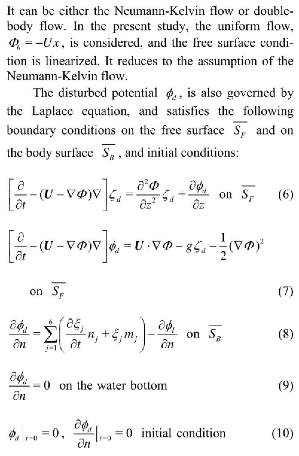
The fluid is assumed to be incompressible and inviscid, and the flow to be irrotational. The governing equation is the Laplace equation for the velocity potential Ψ,

A Cartesian coordinate system, (x, y, z), is taken, which moves with shipʼs mean speed U. The horizontal xoy plane is set on the still water surface with its origin placed at the center of the body, the positive x- axis points towards upstream, the positive z- axis points upward (see Fig.1). A ship translates at a constant forward speed U with respect to a space-fixed reference frame (x0,y0,z0). The total potential Ψ is divided into basis potential Φb, disturbed potential φd, and incident-wave potential φI:
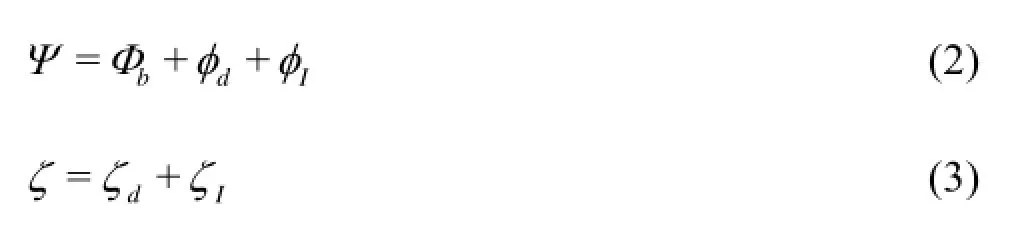
where ζ is the elevation of the free surface, the subscripts, b, d and I denote the basis, disturbed and incident-wave flows, respectively. The basis flow is assumed to be the largest component with its order Φb=O(1), and the disturbed flow φd, and incident flow φI, with their order O(ε). Here, ε denotes some form of small quantity, e.g., beam-to-length ratio of the ship. The disturbed flow can be further divided into steady component φsand unsteady component φu,

The basis flow Φbwhich is a steady component is considered separately for numerical convenience. It can be expressed as

where ξjdenotes the displacement of ship in the jth mode of motion, njis the generalized normal vector with its positive pointing into body from the boundary surface, and defined as

It should be noted that based on the Neumann-Kelvin linearization, the non-zero m- terms are m5=Un3, and m6=-Un2.
1.2Pressure components
By using the decomposed form of the total potential Ψ in Eq.(2), the pressure on the body can be expressed as

By setting pa=0, the linearized pressure is then decomposed into the steady pressure ps, unsteady pressure pu, and hydrostatic pressure pcin the following form

2. Numerical implementation
2.1Boundary integral equation
A boundary integral equation (BIE) for the potential components, Φ anddφ, over the whole boundary surfacesTS, can be derived through Greenʼs second identity in the form

where P is a field point, Q is a source point, C( P) is the solid angle at the field point P, STincludesbody surface, free surface, water bottom, and control surface.
A simple Rankine source with its mirror image reflected in the water bottom surface is adopted as the Green function as follows
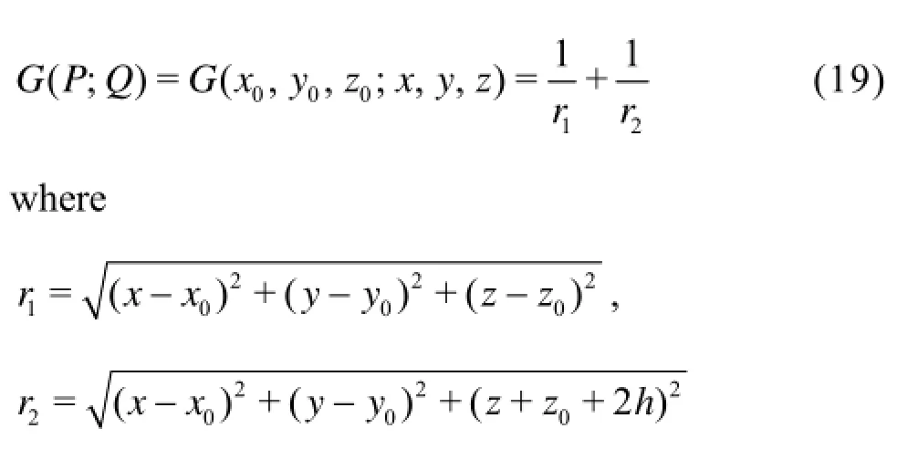
Here, h denotes the water depth. With this Green function and the boundary condition of Eq.(9), the integral on the water bottom can be zero and be removed.
The discretized form of the BIE can be written as
where the influence coefficients A1, A2and C1, C2in the matrices are integrated numerically over each quadratic isoparametric element with quadratic order. The velocity potential on the body surface and the normal velocity on the free surface are unknowns, which are determined by solving the Eq.(20). Once they are determined, the velocity potential and position on the free surface are then updated from Eqs.(6)-(7) by an iterative time-marching scheme, which is described in the following subsection.
2.2Iterative time marching
An iterative scheme is introduced in the procedure of time-marching for numerical stability and accuracy. Details of this iterative time-marching scheme is stated as follows.
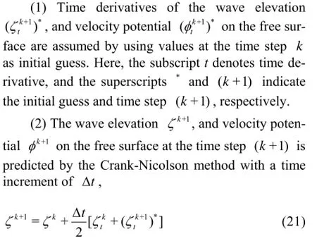

(3) The normal velocity on the free surface and the velocity potential on the body surface are obtained by solving the Eq.(20).
(4) ζtk+1and φtk+1are newly obtained by updating the free surface, Eqs.(6)-(7).

3. Numerical results and discussions
An iterative Rankine boundary element method for seakeeping analysis has been developed and confirmed to be accurate and stable in the steady problem[18,19]. In the present study, this method is extended to analyze the diffraction unsteady problem of a ship advancing with a constant forward speed in waves.
The configuration of computational domain is similar to that used in the steady problem[19], which is rectangular and truncated at some distance from the ship. The damping beach is installed at the outer portion of the free surface, except the downstream side. Since the flow around a symmetric body is naturally symmetric about the xoz plane, half of computational domain is used for saving CPU-time. To avoid numerical oscillation, the ship speed is gradually increased from zero to a specified constant value of U. First, sensitivity studies of the computational domain size, mesh size, and time step are carried out. Then, the performance of the iterative Rankine BEM for the unsteady diffraction problem is assessed by a modified Wigley hull advancing in regular waves. Extensive results, including exciting forces on the hull, diffraction wave patterns and pressure distributions are illustrated and compared with available experimental data and other numerical methods.
3.1Mesh for numerical model
The modified Wigley model can be expressed mathematically as
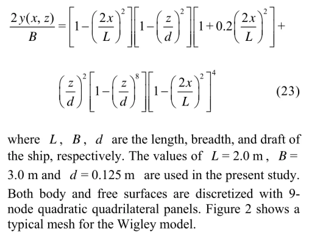

Fig.2 Mesh configuration for a modified Wigley hull


Fig.3 Sensitivity of exciting forces to domain size for the Wigley hull with forward speed Fr=0.20
3.2Convergence study
Convergence study for the present numerical model has been carried out and confirmed by a steady ship-wave problem in He and Kashiwagi[18]. For clarity, convergence study for an unsteady diffraction problem was carried out only for the computational domain size, mesh size, and time step.
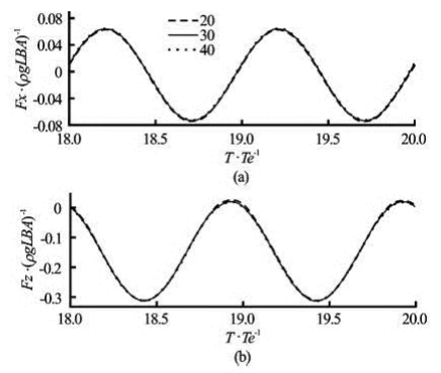
Fig.4 Sensitivity of exciting forces to grid size for the Wigley hull with forward speed Fr=0.20
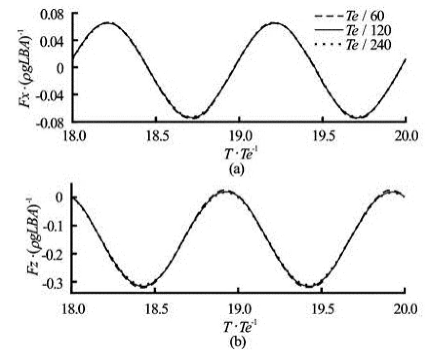
Fig.5 Sensitivity of exciting forces to time step for the Wigley hull with forward speed Fr=0.20
The modified Wigley model with the Froude number Fr=U/gL=0.20 in an incident wave with wavelength λ/L=1.20 is employed in this study. The surge exciting force Fx, and heave exciting force Fz are nondimensionalized by a factor of ρgLBA, and pitch exciting force My is nondimensionalized by a factor of ρgL2BA . Here, ρ is the density of fluid, g is the acceleration due to gravity, A is the amplitude of incident wave. Time is nondimensionalized by the encounter period. Figure 3 shows time evolutions of exciting forces Fx, Fz on the hull with Fr=2.0 and λ/L=1.20 by a damping beach fixed as 0.8L with various domain widths. As was mentioned previously, the free surface is actually truncated in computation, a proper radiation conditionis imposed at the truncated free surface by installing an artificial damping beach. The efficiency of the damping beach has been confirmed in He and Kashiwagi[18]and He[19], so the details are omitted here for clarity. Figures 4-5 show the convergence studies with respect to mesh size and time step, respectively.
It can be found from Fig.3 that the convergence with respect to the domain width is wonderful due to the efficiency of the damping beach. It indicates that the case of domain width 1.2L is sufficient for the present numerical simulation. From Fig.4, it can be found that a converged result is obtained by using 20, 30, and 40 panels along the body length. This quick convergence with relatively small number of panels demonstrates the advantage of the higher-order boundary element method. To obtain more detailed information of the pressure distribution on the ship hull, 50 grids along the ship length are used in the following simulations. From Fig.5, it can also be confirmed that the time step of /240Te is good enough for numerical simulations.

Fig.6 Surge exciting forces of the Wigley hull advancing in head waves with Froude number Fr=0.20
3.3Exciting forces
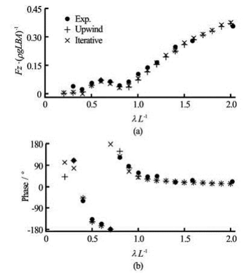
Fig.7 Heave exciting forces of the Wigley hull advancing in head waves with Froude number Fr=0.20

Fig.8 Pitch exciting forces of the Wigley hull advancing in head waves with Froude number Fr=0.20


From Figs. 6-8, it can be found that (1) the exciting forces given by the present numerical method are in good agreement with both experimental data and numerical solutions. (2) The coincidence of the corresponding phases between measured data and computed results from the present method and the upwindscheme-based explicit time-marching method[20]is more wonderful than the coincidence of the exciting forces. (3) A discrepancy is also found between computed results and experimental data, especially in short-wave region. This can be attributed to insufficient number of panels for short waves, since only one type of mesh is used for all frequencies of incident wave. It is confirmed that the present iterative Rankine BEM is capable of calculating the forward-speed diffraction problem accurately.

Fig.9 Snapshots of diffractions wave pattern generated by the Wigley hull with Fr=0.20 and λ/L=0.5 (T/ Te=15.00, 15.25, 15.50, 15.75)
3.4Wave pattern
As was mentioned above, the forward speed of the ship is gradually increased from a state of rest to a specified constant value U. After the ship waves reached periodical, one typical period of the diffraction wave patterns generated by the ship advancing with forward speed Fr=0.20 are shown in Fig.9 for the case with incident wavelength λ/L=0.5, and in Fig.10 for λ/L=1.0, respectively. In each case, four phases in one encounter wave period are plotted at time instants, T/ Te=15.00, 15.25, 15.50 and 15.75. In the contours, positive values are shown with solid line, while negative values are shown by dotted line. And x=0 is set as the mid of the hull, x=-1.0 and x=1.0 are the stern and bow of the ship. It should be pointed out that only the component of the diffraction wave patterns (excluding the component of the incident wave) is shown in Figs.9-10 for clarity.

Fig.10 Snapshots of diffraction wave patterns generated by the Wigley hull with Fr=0.20 and λ/L=1.0 (T/ Te=15.00, 15.25, 15.50, 15.75)
From Figs.9-10, it can be seen that (1) reasonable phenomena are obtained for both two cases with λ/L =0.5, and λ/L=1.0. (2) No reflection wavefrom the side wall appears, which confirms the efficiency of the damping beach. (3) The ship-generated waves shift/propagate to the downstream direction with an interval of Te/4, which corresponds to the evolution of the incident wave. Let us take the time instants T/ Te=15.25 (Fig.9(b)) and T/ Te=15.75 (Fig.9(d)) for further discussion. The phase difference between Fig.9(b) and Fig.9(d) is 0.5Te (180o). It can be obviously confirmed that the wave crest in Fig.9(b) is ideally inversed to be the wave trough in Fig.9(d). this is also the case for wave trough in Fig.9(b). In other words, the phase shift from Fig. 9(b) to Fig.9(d) is 180o. (4) It is well known that under the assumption of linear theory, the so-called k2wave[22]propagating to the downstream direction has the same wave-length of incident wave. It can be confirmed from Figs.9-10 that the wave-length of disturbed wave near the stern of the ship is close to 1.0 m for the case with λ/L=0.5 (corresponding to the wave-length of incident wave, λ=0.5L=1.0 m), and is close to 2.0 m for λ/L=1.0 (corresponding to λ=2.0 m).
3.5Pressure distribution
Finally, corresponding to wave patterns shown in Figs.9-10 with the Froude number Fr=0.20, the distributions of unsteady pressure puon the ship hull are also illustrated in Fig.11 for the case with incident wavelength λ/L=1.0, and in Fig.12 for λ/L=1.0, respectively.
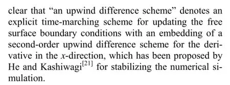
Fig.11 Snapshots of pressure distributions on the Wigley hull with Fr=0.20 and λ/L=0.5 (T/ Te=15.00, 15.25, 15.50, 15.75)
From Fig.11, it can be found that (1) the phenomena for pressure distributions on the hull are very similar with that appeared in the wave pattern. (2) The evolution of the pressure distributions is shifted to the downstream direction. (3) Corresponding to the phase shift in wave pattern shown in Fig.9, the pressure distribution on the hull at time instant T/ Te=15.00 is almost anti-symmetrical with that at T/ Te=15.50. This is also the case for the pair of Te=15.25 and Te=15.75. The similar phenomena also appear in Fig.12. (4) Corresponding to the wave pattern, the pressure distributions have two periods (two crests and two troughs) in the case with incident wavelength λ/ L=0.5, and one period in the case of λ/L=1.0.

Fig.12 Snapshots of pressure distributions on the Wigley hull with Fr=0.20 and λ/L=1.0 (T/ Te=15.00, 15.25, 15.50, 15.75)
4. Conclusions
A 3-D seakeeping analysis approach using an iterative time-marching procedure based on a higherorder BEM has been proposed. It has been extended and validated by the unsteady diffraction problem of a modified Wigley hull advancing in waves. The main conclusions reached from the present study may be summarized as follows:
(1) Convergence studies are carried out, and the convergence with respect to domain size, panel size, and time step is confirmed.
(2) Wave exciting forces on a modified Wigley hull in a wide range of frequencies of incident wave are then presented. Computed results are found to be in good agreement with the corresponding experimental data and other published numerical solutions, which confirmed the capability of the proposed approach in analyzing the unsteady ship-wave diffraction problem.
(3) Further validation is carried out by illustrating the diffraction wave patterns. The wave generated by the ship was confirmed by the so-called2k wave, which propagates to the downstream direction.
(4) The effect of incident wavelength /Lλ on wave pattern and pressure distribution is also investigated and discussed.
Applicability of the iterative Rankine BEM for the unsteady diffraction problem presented in this paper has been confirmed by a Wigley hull. The motion-free problem for a ship advancing in waves is stillunder the development.
Acknowledgement
This work was partially supported by the Fundamental Research Developing Association for Shipbuilding and Offshore (REDAS), Japan.
[1] DATTA R., SEN D. A B-spline solver for the forwardspeed diffraction problem of a floating body in the time domain[J]. Applied Ocean Research, 2006, 28(2): 147-160.
[2] KRING D. C. Ship motions by a three-dimensional Rankine panel method[D]. Doctoral Thesis, Cambridge, Massachusetts, USA: Massachusetts Institute of Technology, 1994.
[3] YASUKAWA H. Time domain analysis of ship motions in waves using BEM (1st report: Computation of hydrodynamic forces)[J]. Transactions-West Japan Society of Naval Architects, 2000, 100: 83-98(In Japanese).
[4] KARA F., TANG C. and VASSALOS D. Time domain three dimensional fully nonlinear computations of steady body-wave interaction problem[J]. Ocean Engineering, 2007, 34(5-6): 776-789.
[5] YASUKAWA H. A Rankine panel method to calculate steady wave-making resistance of a ship taking the effect of sinkage and trim into account[J]. Journal of the Society of Naval Architects of Japan, 1993, 86: 27-35.
[6] NAKOS D. E. Ship wave patterns and motions by a three dimensional Rankine panel method[D]. Doctoral Thesis, Cambridge, Massachusetts, USA: Massachusetts Institute of Technology, 1990.
[7] RAVEN H. C. Nonlinear ship wave calculations using the RAPID method[C]. Sixth International Conference on Numerical Ship Hydrodynamics. Iowa, USA, 1994, 95-118.
[8] GAO Z., ZOU Z. A NURBS-based high-order panel method for three-dimensional radiation and diffraction problems with forward speed[J]. Ocean Engineering, 2008, 35: 1271-1282.
[9] HONG S., CHOI H. Steady and unsteady ship waves by a higher-order boundary element method[C]. Proceedings of Twentieth Symposium on Naval Hydrodynamics. Santa Barbara, 1994, 822-834.
[10] ZHANG X., BANDYK P. and BECK R. F. Time domain simulation of radiation and diffraction forces[J]. Journal of Ship Research, 2010, 54(2): 79-94.
[11] NAKOS D. E., KRING D. C. and SCLAVOUNOS P. D. Rankine panel methods for transient free surface flows[C]. Sixth International Conference on Numerical Ship Hydrodynamics. Iowa, USA, 1994, 613-632.
[12] HUANG Y. Nonlinear ship motions by a Rankine panel method[D]. Doctoral Thesis, Cambridge, Massachusetts, USA: Massachusetts Institute of Technology, 1998.
[13] KIM Y., KIM K. and KIM J. et al. Time-domain analysis of nonlinear motion responses and structural loads on ships and offshore structures: Development of WISH programs[J]. International Journal of Naval Architecture and Ocean Engineering, 2011, 3(1): 37-52.
[14] KASHIWAGI M., OHKUSU M. A new theory for side wall interference effects on forward speed radiation and diffraction Forces[J]. Ship Technology Research, 1991, 38(1): 17-47.
[15] GOU Y., CHEN X., and TENG B. A time-domain boundary element method for wave diffraction in a twolayer fluid[J]. Journal of Applied Mathematics, 2012, ID 686824.
[16] HE G., KASHIWAGI M. Nonlinear solution for vibration of vertical elastic plate by initial elevation of free surface[J]. International Journal of Offshore and Polar Engineering, 2010, 20(1): 34-40.
[17] HE G., KASHIWAGI M. Numerical analysis of the hydroelastic behavior of a vertical plate due to solitary waves[J]. Journal of Marine Science and Technology, 2012, 17(2): 154-167.
[18] HE G., KASHIWAGI M. Time-domain analysis of steady ship-wave problem using higher-order BEM[J]. International Journal of Offshore and Polar Engineering, 2014, 24(1): 1-10.
[19] HE Guanghua. An iterative Rankine BEM for wave-making analysis of submerged and surface-piercing bodies in finite water depth[J]. Journal of Hydrodynamics, 2013, 25(6): 839-847.
[20] WAKABAYASHI T. Hydrodynamic study on added resistance by means of wave pattern analysis[D]. Master Thesis, Suita, Osaka, Japan: Osaka University, 2012.
[21] HE G., KASHIWAGI M. A time-domain higher-order boundary element method for 3D forward-speed radiation and diffraction problems[J]. Journal of Marine Science and Technology, 2014, 19(2): 228-244.
[22] KASHIWAGI M., IWASHITA H. Ship motions[M]. Tokyo, Japan: Seizando, 2012.
10.1016/S1001-6058(14)60090-1
* Biography: HE Guang-hua (1980-), Male, Ph. D., Professor
杂志排行

水动力学研究与进展 B辑的其它文章
- Retard function and ship motions with forward speed in time-domain*
- Multi-point design optimization of hydrofoil for marine current turbine*
- Sediment rarefaction resuspension and contaminant release under tidal currents*
- Stability of fluid flow in a Brinkman porous medium-A numerical study*
- Vadose-zone moisture dynamics under radiation boundary conditions during a drying process*
- Experimental and numerical study on hydrodynamics of riparian vegetation*