Influence of Setting Error of Tool on Tooth Profile and Contact Point of Face Gear Drive
2014-05-05LiXiaozhen李晓贞ZhuRupeng朱如鹏LiZhengminqing李政民卿LiFajia李发家
LiXiaozhen(李晓贞),Zhu Rupeng(朱如鹏),Li Zhengminqing(李政民卿),Li Fajia(李发家)
College of Mechanical and Electrical Engineering,Nanjing University of Aeronautics and Astronautic,Nanjing,210016,P.R.China
1 Introduction
The face gear drive is a gear driving that a spur pinion meshes with a face gear,which the pinion shaft and face gear shaft can be intersecting or non-intersecting,and the face gear is processed by involute gear sharper cutter.Compared with the bevel gear drive,face gear drive has many advantages[1-3],such as simplified of structure,reduction of weight and noise,better split-power effect,decreased of vibration etc.Therefore,the face gear drive is suitable for application in helicopter transmissions,but a substantial step in the technology of face gear drive is based on processing of high precision face gear.
The performed research is based on application of modern theory that has been research by Litvin,Zhu Rupeng,Zhao Ning,et al[1-10].In the references,the tooth profile and contact specialties of master face gear drive have been researched[4-11],but in machining process,setting error of tool will influence the tooth profile and contact characteristic of face gear drive.Therefore,the influence of the setting error of tool needs to be studied.
2 Tooth Profile Equation of Face Gear with Setting Error of Tool
2.1 Coordinate systems of processing
The processing error of face gear is caused by the errors of gear shaping machine,fixtures of workpiece,setting of shaper cutter,machining deformation,machine tool stiffness,motion error of machine tool,profile error of tool,etc.The errors of gear shaping machine and fixture of workpiece can be regarded as the misalignment of shaper cutter.Therefore,only the processing error caused by setting of shaper cutter is analyzed in the paper.The setting error of shaper cutter includes two forms,one is misalignment of offset of shaper cutter,and the other is misalignment of obliquity of shaper.
The coordinate systems of processing which are with misalignment of offset are shown in Fig.1.The fixed coordinate system of face gear is OF-XFYFZF,and the face gear rotates around the axis of OFZFwith the angular velocity ofωf.The fixed coordinate system of standard shaper cutter for standard installation is OM-XMYMZM,and the shaper cutter rotates around the axis of OMZMwith the angular velocity ofωm.The fixed coordinate system of shaper cutter with misalignment of offset along the axis of OMXMis OT1-XT1YT1ZT1,and the shaper rotates around the axis of OT1ZT1with the angular velocity ofωt1.The fixed coordinate system of shaper with misalignment of offset along the axis of OMYMis OT2-XT2YT2ZT2,and the shaper rotates around the axis of OT2ZT2with the angular velocity ofωt2.The parameters aand b are the offset of coordinate systems of OT2-XT2YT2ZT2and OT1-XT1YT1ZT1from the standard systemOM-XMYMZM,respectively.And parameter d is the location datum of shaper from workpiece of face gear.

Fig.1 Coordinate system with setting error of offset
The coordinate systems of processing which are with misalignment of obliquity are shown in Fig.2.The fixed coordinate systems of face gear and standard shaper of standard installation are the same as coordinate systems in Fig.1.The fixed coordinate system of shaper with misalignment of obliquity rotating around the axis of OMYMis OT3-XT3YT3ZT3,and the shaper rotates around the axis of OT3ZT3with the angular velocity ofωt3.The fixed coordinate system of shaper with misalignment of obliquity rotating around the axis of OMXMis OT4-XT4YT4ZT4,and the shaper rotates around the axis of OT4ZT4with the angular velocity ofωt4.The parametersεaandεbare the deflection angle of coordinates systems of OT3-XT3YT3ZT3and OT4-XT4YT4ZT4from the standard systemOM-XMYMZM,respectively.

Fig.2 Coordinate system with setting error of obliquity
2.2 Equation of standard face gear
Standard face gear is machined by the shaper cutter which is standard installation through envelope theory.In machining process,the shaper cutter is an involute cylindrical gear,and the coordinate system of shaper cutter is shown in Fig.3.The coordinate system OM-XMYMZMis rigidly connected to the shaper.

Fig.3 Coordinate system of shaper
The equation of the tooth surfaceΣMof the shaper cutter is given by[11,12]
where the upper and lower signs correspond to profileⅠandⅡ,respectively;rkis radius of the point on tooth surfaceΣMof shaper which is ex-pressed as rk=rb/cosαk;rbis base radius of shaper;αkis the pressure angle of the point k;θkis the angle between axis of OMYMand vector OMk,and θkis expressed asθk=π/(2·Nm)-invα+invαk,Nmis the teeth number of shaper;ukis the parameter which is along the axis of shaper.
The homogeneous matrixe of equation of tooth surface is given by

According to the meshing relationship between face gear and shaper shown in Fig.1,the homogeneous transformation matrix from the moving coordinate system of shaper Om-XmYmZmto the moving coordinate system of face gear Of-XfYfZfis the following equation

Therefore,the tooth surface of shaper cutter is obtained from Eqs.(2,3)by coordinate transformation.

The envelope condition between shaper cutter and face gear is expressed as[12-14]

Therefore,the tooth surface equation of standard face gear is expressed as

where the parameterφmis the angle of shaper rotates around the axis OMZM.
The profile of standard face gear is obtained by numerical simulation with Matlab2007,which is shown in Fig.4.The number of teeth of the shaper is 30;the number of teeth of the face gear is 120;the module of shaper and face gear is 3mm;the pressure angle of shaper is 25°.

Fig.4 Simulation of tooth surface of standard face gear
2.3 Face gear with processing error of offset
Processing error of face gear with misalignment of offset contains two forms which are shown in Fig.1.One is caused by offset along the axis OMXM,and the other is caused by offset along the axis OMYM.The equation of shaper cutter is the same as Eq.(1),and the difference is the subscript of Eq.(1)are replaced″M″with″T″,which is expressed as

According to the meshing relationship shown in Fig.1,the homogeneous transformation matrix from the moving coordinate system of shaper with setting error Ot-XtYtZtto the moving coordinate system of face gear Of-XfYfZfis expressed as

Matrix MMTis caused by setting error of shaper which is expressed as

When parameter ais zero,matrix MMTis the transformation matrix from coordinate system OT1-XT1YT1ZT1to coordinate system OM-XMYMZM.When parameter bis zero,matrix MMTis the transformation matrix from coordinate system OT2-XT2YT2ZT2to coordinate system OM-XMYMZM.
The tooth surfaceΣTof shaper with misalignment of deflection which is expressed in coordinate systemOf-XfYfZfas

The envelope condition between shaper with misalignment of deflection and face gear is expressed as[12-14]

whereφtis the angle of shaper rotating around the axis OTZT.
Therefore,the equation of face gear with processing error of misalignment of deflection is expressed as

The tooth profile of face gear with processing error of misalignment of offset is obtained by numerical simulation with Matlab 2007,which is shown in Fig.5.When the parameter ais 0.3,0 and-0.3mm and bis 0mm,the surfaceΣFof face gear is shown in Fig.5(a).When the parameter bis 0.3,0and-0.3mm and ais 0mm,the surfaceΣFof face gear is shown in Fig.5(b).

Fig.5 Tooth profile of face gear with machining error of misalignment of offset
According to Fig.5(a),the tooth profile of face gear with processing error which are misalignment of offset along the axis OMYMkeeps invariant,but the position of tooth profile will move along the axis of face gear.If parameter ais more than zero,the tooth profile moves along the positive direction of the axis of the face gear,and if parameter ais less than zero,the moving direction is opposite.
According to Fig.5(b),the tooth profile of face gear with processing error which is misalignment of offset along the axis OMXMkeeps invariant,too,but the position of tooth profile will rotate around the axis of face gear.If parameter bis more than zero,the tooth profile rotates in the clockwise direction of the axis of the face gear,and if parameter bis less than zero,the rotating direction is opposite.
2.4 Face gear with processing error of obliquity
Processing error of face gear with misalignment of obliquity contains two forms which are shown in Fig.2.One is caused by the shaper whirling around the axis OMYM,and the other is caused by the shaper whirling around the axis OMXM.The surface equation of shaper is the same as Eq.(7).
According to the meshing relationship shown in Fig.2,the homogeneous transformation matrix Mftfrom the moving coordinate system with processing error of shaper Ot-XtYtZtto the moving coordinate system of face gear Of-XfYfZfis the same as Eq.(8),but the matrix MMTwhich is transformation matrix from the fixed coordinate OT-XTYTZTto the fixed coordinate OM-XMYMZMis different from Eq.(9),and matrix MMTis expressed as
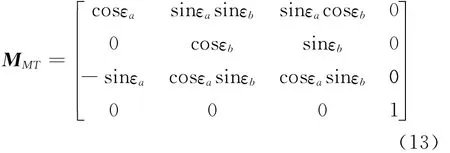
where parameterεais the angle of misalignment of obliquity whirling around the axis OMYM,parameterεbthe angle of misalignment of obliquity whirling around the axis OMXM.When parameter εa=0,matrix MMTis the transformation matrix from coordinate systemOT4-XT4YT4ZT4to coordinate system OM-XMYMZM.When parameterεb=0,matrix MMTis the transformation matrix from coordinate system OT3-XT3YT3ZT3to coordinate systemOM-XMYMZM.
The tooth profile of face gear with processing error which is misalignment of obliquity is obtained by numerical simulation with Matlab2007,which is shown in Fig.6.When the parameterεais 0.3°,0°and-0.3°andεbis 0°,the tooth surfaceΣFof face gear is shown in Fig.6(a).When the parameterεbis 0.3°,0°,-0.3°andεais 0°,the tooth surfaceΣFof face gear is shown in Fig.6(b).

Fig.6 Profile of face gear with machining error of misalignment of obliquity
According to Fig.6(a),the tooth profile of face gear with processing error of obliquity whirling around OMYMis deformation.If parameterεais more than zero,the work face of right tooth profile is up,while the fillet surface of right tooth profile is down,and the left tooth profile change in opposite direction.If parameterεais less than zero,the change direction is opposite.
According to Fig.6(b),the tooth profile of face gear with processing error of obliquity whirling around OMXMis deformation.If parameterεbis more than zero,the medial tooth profile is up,while the lateral tooth profile is down.If parameterεbis less than zero,the rotating direction is opposite.
At these parameters,the maximum error of influence of setting error of tool on tooth profile is 1.26%.
3 Contact Specialties of Face Gear Drive with Processing Error
The contact points of face gear with processing error meshing with spur pinion will be different for various types of processing error,and the chapter will analyze the influence of processing error to the position of contact points.
According to the envelope theory,the equation of contact line of face gear with processing error meshing with shaper cutter is expressed as Eq.(12),and the contact lines are shown in Fig.4.
The transformation equation of tooth profile of spur pinion from moving coordinate of spur pinion to moving coordinate of master shaper is expressed as

The number NTof the teeth of the pinion is less than the number Nmof the teeth of the shaper:Nm-NT=2or 3[13,14],and the pinion and the shaper are regarded as internal gear pair.rPis the tooth surface equation of spur pinion;Mmpis the homogeneous transformation matrix from moving coordinate system of pinion to moving coordinate system of shaper.
The envelope condition between spur pinion and shaper is expressed as

Therefore,the equation of contact points on the surfaceΣfis expressed as
The numerical simulations of position of contact points on tooth profile of face gear drive with processing error of misalignment of offset and obliquity are shown in Figs.7,8,respectively.
According to Figs.7(a,b),the position of contact points on tooth profile of face gear will be changed with the tooth profile of face gear with processing error of misalignment of offset,but the relative position is not sensitive to the misalignment of offset.The signs″△″″*″and″+″represent the position of contact points when the parameters aand bare 0.3,0and-0.3mm,respectively.

Fig.7 Contact points of face gear with machining error of misalignment of deflection
According to Figs.8(a,b),the position of contact points on tooth profile of face gear will be changed with the tooth profile of face gear with machining error of misalignment of obliquity,but the relative position is not sensitive to the misalignment of obliquity.The signs″△″″*″and″+″represent the position of contact points when the parametersεaandεbare 0.3°,0°and -0.3°,respectively.
Compared with the change of various types of processing errors,the contact points of face gear drive move with the teeth profile which are processed with processing error of misalignment of offset,and the relative position keep invariant;the contact points of face gear drive will change with deformation of the tooth profile of face gear which are processed with processing error of misalignment of obliquity,and the relative position of contact points are changed a little.

Fig.8 Contact points of face gear with machining error of misalignment of obliquity
According to the above analysis and Fig.8,the position of contact points of face gear drive will have a tiny change with the face gear which is processed by shaper cutter with the setting error.The pressure along axis″X″is zero in face gear drive.Therefore,the tiny change of contact points will not effect the transmission characteristics of face gear drive.At these parameters,the maximum error of influence of setting error of tool on position of contact points is 0.73%.
4 Conclusions
Based on the performed research,the following conclusion might be drawn:
(1)The influence of obliquity error on tooth profile is bigger than offset error,and the offset error will make the profile of face gear translation,the obliquity error will make the profile of face gear deformation,but the influence are all tiny.
(2)The processing error will make the position of contact points moving with the tooth profile of face gear,but the relative position change a little.
In conclusion,the tooth profile and position of contact points of face gear drive are not sensitive to the processing error.
[1] Litvin F L,Zhang Y,Wang J C,et al.Design an geometry of face-gear drives [J].Transactions of ASME,1992,114(12):642-647.
[2] Litvin F L,Egelja A.Handbook on face gear drive with a spur involute pinion[R].NASA-CR-2000-209909,2000.
[3] Chung T D,Chang S H.The undercutting and pointing of face gear[J].Journal of the Chinese Institute of Engineerings,1998,21(2):181-188.
[4] Litvin F L,Ignacio Gonzalez-Perez,Alfonso Fuentes,et al.Design,generation and stress analysis of facegear drive with helical pinion[J].Computer Method in Applied Mechanics and Engineering,2005,194:3870-3901.
[5] Litvin F L,Alfonso Fuentes,Claudio Zanzi,et al.Face gear drive with spur involute pinion:Geometry,generation by a worm,stress analysis[J].Computer Method in Applied Mechanics and Engineering,2002,191(25/26):2785-2813.
[6] Heath G F,Filler R R,Tan Jie.Development of face gear technology for industrial and aerospace power transmission[R].NASA/CR-2002-211320,2002.
[7] Claudio Zanzi,Pedrero J I.Application of geometry of face gear drive[J].Computer Methods in Applied Mechanics and Engineering,2005,194:3047-3066.
[8] UlrichKissling,Stefan Beermann.Face gears:Geometry and strength[M].USA:Gear Technology,2007:54-61.
[9] Zhu Rupeng,Pan Shengcai.Current state and development of research on face gear drive[J].Journal of Nanjing University of Aeronautics & Astronautics,1997,29(3):385-361.(in Chinese)
[10]ZhaoNing,Liu Changqing.Study on grinding machine of face gears[J].Machinery Design & Manufacture,2007,10(10):151-152.(in Chinese)
[11]Guo Hui,Zhao Ning,Fang Zongde,et al.Research on bending strength of face-gear transmission based on contact finite element method[J].Journal of Aerospace Power,2008,23(8):1438-1442.(in Chinese)
[12]Li Zhengminqing,Zhu Rupeng.Process method of face-gear drive with spur involute pinion with the shaping machine[J].Journal of Chongqing University,2007,30(5):55-58.(in Chinese)
[13]Li Zhengminqing,Zhu Rupeng.A study of worm of hobbing or grinding wheel for face gear[J].Mechanical Science and Technology for Aerospace Engineering,2009,28(1):98-101.(in Chinese)
[14]Wang Yanzhong,Wu Canhui,Ge Xuyang,et al.Basal worm-designing method of face-gear hob[J].Journal of Beijing University of Aeronautics and Astronautics,2009,35(2):166-169.(in Chinese)
杂志排行

Transactions of Nanjing University of Aeronautics and Astronautics的其它文章
- Hybrid Multipopulation Cellular Genetic Algorithm and Its Performance
- Development and Prospectives of Ultra-High-Speed Grinding Technology
- Threshold Selection Method Based on Reciprocal Gray Entropy and Artificial Bee Colony Optimization
- Optimal Power Management for Antagonizing Between Radar and Jamming Based on Continuous Game Theory
- Parameter Optimization Method for Gaussian Mixture Model with Data Evolution
- Runge-Kutta Multi-resolution Time-Domain Method for Modeling 3DDielectric Curved Objects