Spatial Load Balancing in Wide-Area Wireless Networks
2011-06-19KambizAzarianRavindraPatwardhanChrisLottDonnaGhoshRadhikaGowaikarandRashidAttar
Kambiz Azarian,Ravindra Patwardhan,Chris Lott,Donna Ghosh,Radhika Gowaikar,and Rashid Attar
(Qualcomm Inc.,San Diego,CA 92121,U.S.A)
Abstract:Load balancing is typically used in the frequency domain of cellular wireless networks to balance paging,access,and traffic load across the available bandwidth.In this paper,we extend load balancing into the spatial domain,and we develop two approaches—network load balancing and single-carrier multilink—for spatial load balancing.Although these techniques are mostly applied to cellular wireless networks and Wi-Finetworks,we show how they can be applied to EV-DO,a 3G cellular data network.When a device has more than one candidate server,these techniques can be used to determine the quality of the channel between a server and the device and to determine the load on each server.The proposed techniques leverage the advantages of existing EV-DO network architecture and are fully backward compatible.Network operators can substantially increase network capacity and improve user experience by using these techniques.Combining load balancing in the frequency and spatial domains improves connectivity within a network and allows resources to be optimally allocated according to the p-fair criterion.Combined load balancing further improves performance.
Keyw ords:CDMA 2000;EV-DO;DO-RevC;high rate packet data(HRPD);network load balancing(NLB);single-carrier multilink(SCML)
1 Introduction
D emand for data in wireless networks is spatially non-uniform,which leads to chokepoint sectors,and it is also time-varying,which means that chokepoint sector locations change.Chokepoint sectors operate at or close to the maximum load;therefore,they determine network performance,user perception of network performance and,ultimately,user experience.In a network with fixed assets and unbalanced loading,spatial load balancing uses network resources from neighbors of chokepoint sectors to serve users in the chokepoint sector.
This increases the capacity of the network.
Field data collected from commercially deployed networks shows that only a small fraction of sectors are chokepoints at any given time and that chokepoint sectors typically have several lightly loaded neighbor sectors.Fig.1 shows the distribution of sector loading(per-sector forward link(FL)slot use)during peak hour in a metropolitan commercial EV-DO network where sectors with low slot use are lightly loaded.Operators add hardware by splitting cells near the chokepoint sectors or increase bandwidth by adding carriers to the chokepoint sectors.Such actions lead to networks that are designed for worst-case scenarios and are therefore underused most of the time.
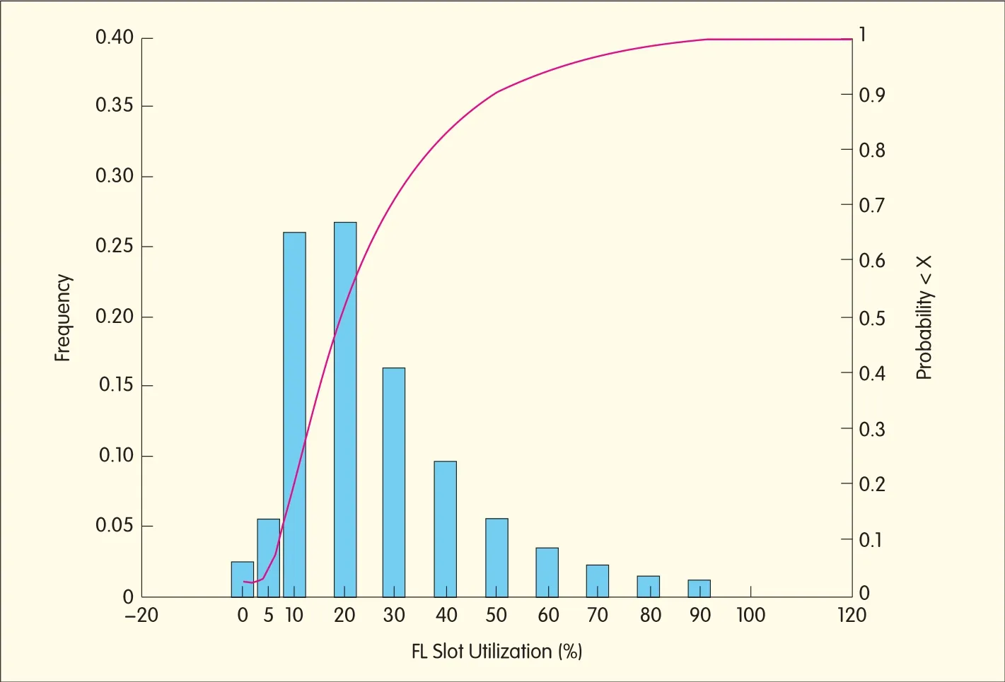
▲Figure 1.Per-sector FLslot use during peak hour(mean FLuse is 26%).
The spatialload-balancing techniques discussed in this paper are network load balancing(NLB)and single-carrier multilink(SCML).
In NLB,a device is opportunistically reassigned from a heavily loaded sector to a lightly loaded sector,even if the channel quality of the heavily loaded sector is better.The end result is increased capacity for the chokepoint sector from offloading the most expensive users(poor channel quality means that the network has to allocate more resources for a given amount of traffic)to the neighbor sector.
With SCML,any device that can simultaneously process two or more independent data streams can achieve the benefits of a multicarrier network,even though the device may be in the hand-off region of a single-carrier deployment.
With multicarrier EV-DO,the EV-DO carriers that serve a mobile device use different carrier frequencies and may originate from the same cell or different cells.With SCML,the same carrier frequency serves the mobile device with independent data streams and from different sectors.NLBimproves performance when the chokepoint sector is loaded,and SCML improves performance at all load levels.In this paper,we describe how these techniques augment load-balancing in the frequency domain.
In Section 2,we provide necessary background information.In sections 3 and 4,we discuss the concepts,algorithms,and implementations of NLB and SCML.In section 5,we perform simulations to determine the performance of NLBand SCML.In section 6,we make concluding remarks and discuss future work.
2 Background
2.1 Server Selection
When the access terminal(AT)in a wireless network has a choice of serving sectors,it typically selects the server with the best channel quality.(Here,hysteresis based on channel quality and time is not discussed for the sake of simplicity.)In EV-DO,the AT selects the best forward layer(FL)server from the candidate servers that have a corresponding reverse link(RL)of acceptable quality.If the DRCLock bit on,the RL quality is acceptable;if the DRCLock bit is off,the RLquality is unacceptable.The DRCLock bit itself is set according to the quality of the RL overhead channels received at the base station.
2.2 Multicarrier Operation
When an ATin EV-DO is assigned multiple carriers,those carriers may originate from the same sector or different sectors(one forward-link serving sector for each carrier)[1],[2].Commercial EV-DO uses independent schedulers on each sector carrier,and multicarrier EV-DO uses multilink radio link protocol(RLP)on each sector carrier.Multilink RLPenables the network to split a data stream at the transmitter across multiple independent schedulers and to combine the data stream at the receiver while ensuring early detection of packet loss and in-order delivery of RLPpackets[3].When multiple links(or carriers)are assigned to an AT,the network distributes forward-link data across available links.Data throughput on each link can be different,and the throughput varies over time.Enhanced flow control(EFC)ensures FL data is distributed across links according to link throughput and that the data distribution adapts to changes in link throughputs.
Each forward link in EV-DO requires reverse-link feedback to indicate FL channel quality and acknowledgements(ACK/NACK)for physical-layer HARQ.EV-DO supports multiple feedback multiplexing modes.RLoverhead of multiple FLcarriers can be transmitted over a single RL carrier to minimize the RLpilot overhead.
2.3 FL Load Metrics
We introduce a new metric for the loading at each sector.This metric is the average number of non-empty queues at the sector carrier.It is calculated for each slot(which takes 1.66 ms)and is fed to a filter with a time-constant of a few seconds to generate the Neff metric.
Networks are at times backhaul-limited,and this leads to the air link at the BTSbeing underused.A backhaul-limited sector-carrier may not appear to be loaded because of queue under-run.Therefore,backhaul limit must be accounted for when calculating loading level at each sector-carrier.Ametric for backhaul limit is the number of unfilled flow control requests for a sector-carrier that has non-empty ATqueues at the BSC.
2.4 Operator Deployments
Operators deploy wireless data networks according to data demand.Hence,operator deployments are not uniform and have spatial variations in the number of carriers deployed.
Typically,a large area in an operator network has three or less deployed carriers.In regions of the network with just one carrier,multicarrier EV-DO cannot improve performance of ATs with multicarrier capability.
2.5 Smart Carrier Management
EV-DO access networks(ANs)assign the best-available carrier to an ATby transporting the load levels across carriers(on the forward and reverse links)and the channelquality from the ATs to each of the candidate carriers.
3 Network Load Balancing
NLBis shown in Fig.2.PN(b)is the best FL sector for the user;however,PN(b)is heavily loaded and the neighboring sector,PN(a),is lightly loaded.If PN(b)is selected as the serving sector,it has better signal-to-interference plus noise ratio(SINR)than PN(a)but is scheduled much less time than in PN(a)because of heavy loading.Thus,even at the cost of FL SINRdegradation,the AT’s throughput can increase when the FL loading differential is sufficient to offset the SINRdegradation.
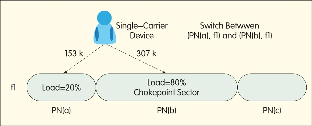
◀Figure 2.Network load balancing.
An important consideration in NLB is its interaction with the partial loading of neighboring sectors.The SINRof the traffic channel in the chokepoint sector is higher than the SINRof the pilot channel(only applicable to EV-DO)because of lesser interference from the lightly loaded neighboring sector.If the ATis served by the lightly loaded neighbor,then the chokepoint sector with high neighbor loading gives strong interference.If a network has a large number of ATs with the ability to spatially null the strong interferer,the network can gain more from NLB.In addition,offloading users to lightly loaded neighboring sectors drives those sectors towards higher slot use,and these sectors then cause more interference to the chokepoint sector.
This effect limits the loading differential across sectors where NLBis beneficial.The NLB algorithms also specify minimum FL channelquality to ensure the ATdoes not choose an extremely weak FL server,regardless of the load difference between neighboring sectors.This allows the ATto continue to receive the FL control channels with the desired performance.There are two types of NLBalgorithm:one for existing ATs deployed by operators and another for new ATs.
3.1 Network Load Balancing for Legacy ATs
Implementation of the NLB algorithm for legacy ATs does not require the AT to have any additionalcapability.Each sector-carrier periodically provides its load information(Neff)to the BSC.The BSC also receives FLpilot strength information from ATs via a RouteUpdateRequest in EV-DO every 2 to 4 seconds.With this information,the BSCcan select suitable legacy ATs and induce them to change serving sectors by setting the DRCLock bit(RL quality indicator)that corresponds to the chokepoint sector to off(indicating poor RLquality).
3.2 Network Load Balancing for New ATs
The AN assists NLB for new ATs.Each sector-carrier periodically provides its Neff to the BSC.The BSC propagates this to all members in the neighbor list of each sector-carrier.Each sector-carrier periodically broadcasts its load level—as well as the load level for allsector-carriers in its neighbor list—on the synchronous control channel.The server selection algorithm at the access terminal then uses not only FL channelquality and RL channel quality(DRCLock bit)but also the FLload level from the candidate serving sectors on each carrier.The server selection metric is modified to use the FL channelquality and the FL load level,and the constraint whereby the ATselects a serving sector from sectors with acceptable RLquality is maintained.
4 Single-Carrier Multilink
EV-DO ATs are multicarrier enabled,which means they can receive data on multiple links regardless of whether these links are from the same sectors on the same carrier.This capability can be harnessed with SCMLto allow multicarrier-enabled ATs to have improved performance even in regions of the network with less than three carriers.Because SCML is beneficial only in handoff regions(typically characterized by lower SINRand less-than-ideal performance),it delivers gains where they are needed most.With SCML,the network can serve the ATusing multiple servers on a carrier.Each FL server creates a link between the AN and AT.SCMLallows multiple links on a single carrier,and that is why it is called single-carrier multilink.An AT’s active set are those sectors that control the power of the AT on the RL and can serve the ATon the FL.SCMLenhances FLdata rate when all sectors in the AT’s active set are lightly loaded,and it balances the load when some chokepoint sectors are in the AT’s active set.For an ATthat can receive FL data from n links simultaneously,SCMLallows the AN to assign additional links and enhance FL throughput when the number of carriers assigned to ATis<n and the AThas multiple sectors in the active set.SCML leverages the advantages of EV-DO,and in the following,we explain some changes to existing EV-DO.
4.1 Reverse Link Feedback Multiplexing
For each additional link assigned using SCML,an additional set of RL feedback channels is required.This is sent over a single RL carrier using reverse link feedback multiplexing.The multiplexing is supported by methods such as basic feedback multiplexing(BFM)and enhanced feedback multiplexing(EFM).
4.2 Distributed Network Scheduling
The network can more flexibly schedule FL data when an ATis served on multiple links.Distributed network scheduling(DNS)improves network efficiency by biasing FL data delivery towards a better link[4].When FL slot use is 100%,DNSfairly schedules across all ATs regardless of the number of links assigned.When FL slot use is less than 100%,DNSallows SCMLATs to achieve some trunking gain by using free slots on each link,which results in a higher FLdata rate for SCMLATs.
4.3 Receiving Diversity and Interference Nulling
An SCML ATmay be simultaneously served from multiple links on same carrier,resulting in self interference.
The ATis simultaneously served from two sectors that interfere with each other.Even if no other ATis present in the system,each link assigned to the SCML ATreceives interference from another link(s).To achieve gains from multiple links,the ATmust overcome the interference.Some EV-DO receiving diversity implementations can spatially null a strong interferer,and this is the key to SCML.The network should limit SCML assignment to receiving diversity ATs with spatial nulling capabilities.ATs with more Rx antennas are typically capable of superior spatial nulling of strong interferers,and therefore,SCML performance improves with an increase in number of ATRx antennas.
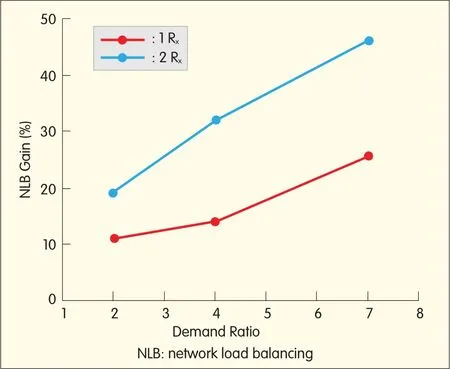
▲Figure 3.NLBgain as a function of demand ratio.
4.4 Smart Carrier Management
The smart carrier management algorithm can be modified to take the SCML capability of a device into account.The network allocates and removes SCML based on signal conditions,and this ensures that additionallinks can provide reasonable throughput.Links across carriers are preferred because they are orthogonal and provide trunking(multiplexing)gain.If the ATcan support more links than assigned carriers,AN uses SCML to assign additional links on a carrier according to available FL control resources and RL load on that carrier.
The additional links provide trunking gain in the spatial dimension.Once the ATserver selection algorithm has been assigned multiple links by the smart-carrier management algorithm,the ATserver-selection algorithm chooses the best link(s)by using the FL channel quality and FLload.This is similar to the NLB algorithm for new ATs.The AN has multiple paths that it can use to serve FLdata,and DNSallows network throughput to be optimized.
5 Performance
Simulations reveal the performance gained using NLB and SCML.The performance results are valid for a seven-cell layout with a center-cell demand model;that is,the center cellhas multiple times the number of users of neighboring cells.The ratio of the number of users in the center cell to users in the neighboring cell is the demand ratio.Except for Fig.3,which shows load-balancing gain as a function of demand ratio,all other figures are valid for a demand ratio of three.Users have an http traffic model;that is,they repeat downloading a sample http webpage according to a random arrival process with a fixed rate.To determine performance in a particular scenario,for example,dual-antenna or dual-carrier devices with load balancing enabled,simulations are performed for a range of download rates.Each simulation is then characterized in terms of download rate(the average number of webpages downloaded per minute per high-demand sector-carrier)and the tail of the page delay.The tail of the page delay is defined as follows:The delay for each downloaded http page is the time between when the first byte of the page is queued in the BSC to the time the last byte is downloaded by the user.
Then,the page delay CDF(across allusers and all webpages)is formed,and the ninety percentile delay is chosen as the tailpage delay.The tail page delay versus rate curve for the scenario is then formed from allsuch rate-delay pairs.Both single and dual-antenna devices are simulated.Single and multicarrier devices are also simulated.
5.1 Load-Balancing Gain for Single-Carrier Devices
Fig.4 shows the tail page delay versus rate curves for single-carrier devices with one or two antennas.Load balancing provides significant gain only when the load level is sufficiently large,that is,when the solid red and blue curves(which represent the baseline and new NLBcases for two-antenna devices,respectively)fall on top of each other at low rates.Because of the low load differential at low load levels,no user is offloaded to another sector and there is no load balancing gain.Also in Fig.4,the load-balancing gains for single-antenna devices(new or legacy)are not as large as those for dual-antenna devices.Once a user is offloaded from a heavily loaded sector to a lightly loaded one,the heavily loaded sector appears as a strong interferer.This occurs because the user receives a stronger signal from the heavily loaded sector than from the lightly loaded one.Dual-antenna devices can spatially null some of the interference.Single-antenna devices lack such capability and thus achieve lower load balancing gains.Multiple receiving antennas and special null of a strong interferer becomes even more important for SCMLbecause users usually suffer self-interference.Consequently,NLBand SCMLare recommended only for dual-antenna devices.
Fig.4 also shows that although the load-balancing gain for legacy devices is not as large as the gain for new devices,they are comparable.The gain is reduced because the BSC,which induces load balancing for legacy terminals,does not have accurate information about user SINR.
Fig.3 shows that the load-balancing gain increases with the demand ratio,that is,the ratio of users in the center cell to users in the neighbor cell.This is a result of more users being offloaded from the heavily loaded center cell to the lightly loaded neighboring cells as the demand differentialincreases.Load balancing provides substantialgains over a wide range of demand ratios.
5.2 Load-Balancing Gain for Multicarrier Devices
Fig.5 shows the tail page delay versus rate curves for single and multicarrier devices(the maximum number of assigned carriers is two).
The single and multicarrier devices have two antennas.Load-balancing gain improves when a second carrier is added.As carriers are added,users experience trunking(multiplexing)gain.
The horizontal distance between the magenta and red curves in Fig.5 represents the trunking gain of dual-antenna devices when a second carrier is added.Trunking gain is also a function of load level.As the load levelincreases,the trunking gain decreases.
The magenta and red curves in Fig.5 merge as rate is sufficiently increased.Both baseline and NLBcases achieve trunking gain when a second carrier is added;the trunking gain achieved in the latter case is more substantial because some users hand off to lightly loaded neighbors.
In these cases,there is a dual benefit from NLB—spatial load-balancing combined with load-balancing in the frequency domain—and this magnifies the gains from spatial load balancing.NLBcombined with multicarrier deployments increases network capacity when the network is loaded and also substantially improves UE.
This means faster web-page downloads when the network is not as loaded.
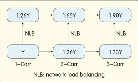
Fig.6 and Fig.7 show the relationship between load balancing and trunking gains for two-antenna devices at low(7 second tail page delay)and high(13 second tail page delay)load levels.Specifically,Xin Fig.6 denotes the network capacity for a single-carrier deployment with dual-antenna devices were the tail page delay does not exceed 7 seconds.The coefficients in Fig.6 represent the per-carrier network capacity gain when load balancing is enabled or additional carriers are added.At low load levels,per-carrier trunking gain(63%)created by adding a second carrier is much larger than the gain from load balancing(5%).NLB provides significant gain when sectors are sufficiently loaded;trunking gain is greater when load level is smaller.In contrast,Fig.7 shows that at high load levels,load balancing provides the same gain(26%)as adding the second carrier.Thus,combining multicarrier deployments with per-carrier load balancing provides substantial gain over a wide range of load levels.
5.3 SCMLPerformance
Fig.8 shows FL burst rate as a single-carrier user moves between two neighboring cells.With no SCML,a user’s burst rate reduces as the AT moves away from the center of the cell and approaches the celledge.The burst rate starts increasing again as the ATapproaches the center of the neighboring cell.With SCML,a user’s burst rate is significantly improved near the cell edge because the user is served by two sectors at the celledge.
Thus SCML can provide ATs with a more uniform UEas the user moves within the network.
▲Figure 7.NLBgains for dual-antenna multicarrier devices at a high load-level(13 seconds tail page delay).
Fig.9 shows the tail page delay versus rate curves for dual-antenna single-carrier devices.The cluster consists of seven sectors,and the center sector has three times the number of users of its neighboring sectors.Load balancing provides substantialgains only when load levelis high,whereas SCML provides substantialgains at all load levels.At low load levels,SCML exploits spatial trunking across sectors,whereas at high load levels,SCMLasymptotes to NLBwhere the ATis effectively served by one sector only.Single-carrier multilink is therefore a form of soft-network load balancing.
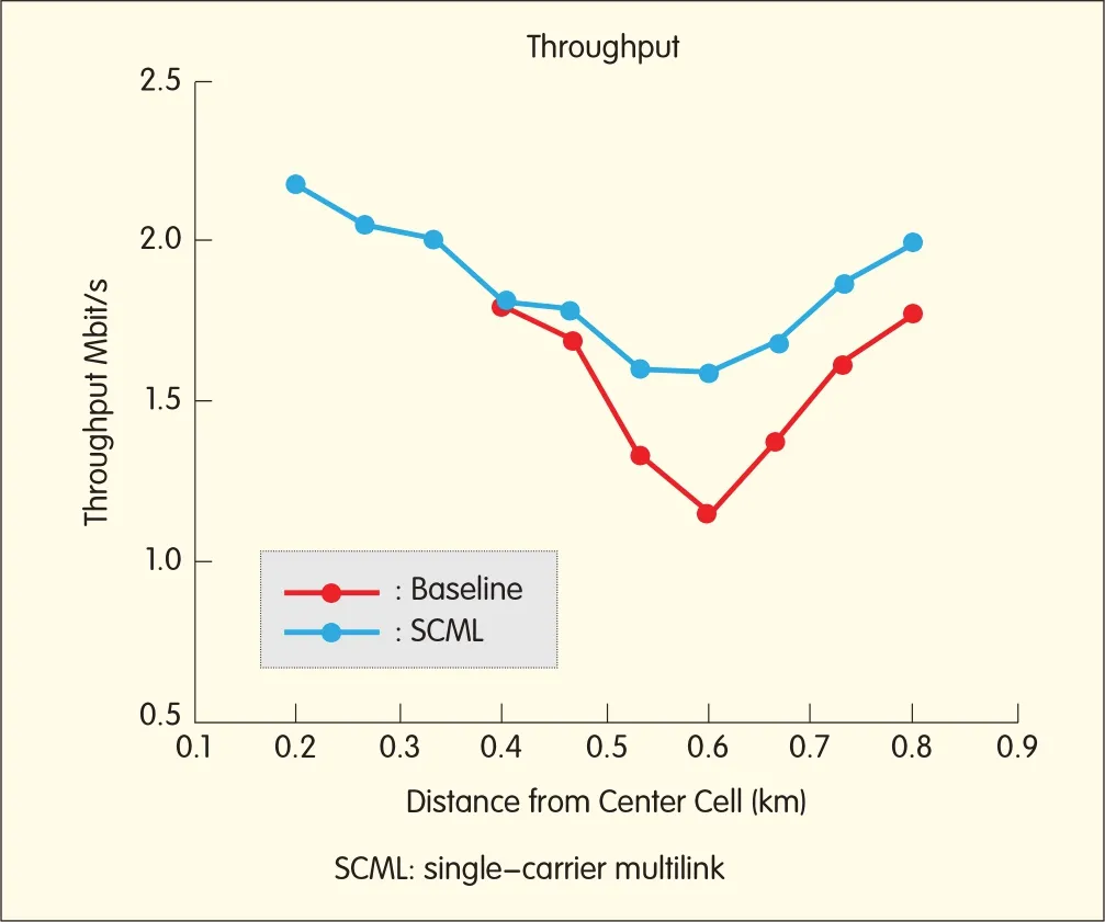
◀Figure 8.Burst rate for a single-carrier user moving between two neighboring cells.
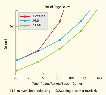
▲Figure 9.SCMLgain for dual-antenna single-carrier devices(300 kBper webpage).
6 Conclusions
This paper gives an overview of load balancing in the spatial dimension.NLB and SCMLare introduced,and related algorithms,implementation,and performance are presented.We also show that load balancing in the spatial dimension and frequency dimension can be combined to amplify gains in networks where capacity is constrained.
The proposed methods are fully backward compatible and leverage the advantages of EV-DO networks thus increasing
the return on investment for these networks.NLB,in particular,is applicable to legacy devices.These techniques improve user experience when the sector is not operating at load.
Further improvements to NLB and SCMLcan be made with higher-order receiving diversity at the device.This enables further improvements in spatial nulling,which allows the device to be simultaneously served by even more sectors on the same carrier.
Similar techniques,such as single-frequency dual cell(SFDC),are being developed for UMTSnetworks and are applicable to LTEnetworks as well.NLBand SCMLare both applicable to local-area wireless networks.
杂志排行

ZTE Communications的其它文章
- Advances in Digital Front-End and Softw are RFProcessing:PartⅡ
- Frost&Sullivan Recognizes ZTE as 2011 LTEVendor of the Year
- ZTE Establishes Global Consumer Brand Ambitions in 2011
- Polyphase Filter Banks for Embedded Sample Rate Changes in Digital Radio Front-Ends
- Design of Software-Defined Down-Conversion and Up-Conversion:An Overview
- Practical Non-Uniform Channelization for Multistandard Base Stations