超高真空环境下测试产品的放气分析
2010-03-20孙立臣闫荣鑫刘恩均史纪军张海峰孙立志北京卫星环境工程研究所北京100094
汪 力,孙立臣,闫荣鑫,刘恩均,史纪军,张海峰,孙立志(北京卫星环境工程研究所,北京 100094)
0 Introduction
It is known that every solid material can dissolve and absorb some gases in the atmosphere. When these materials are put into a vacuum chamber (as an environment), they will give off the adsorbed or dissolved gases and vapors, which is called outgassing[1]. Outgassing in the ultra-high vacuum system includes outgassing of ultra-high vacuum facility and outgassing of testing products, and the latter of which is analyzed in this paper.
Many testing products of spacecraft, such as driving framework, relay and conversion switch, are often put into the ultra-high vacuum facility to test their properties. The outgassing of these testing products is not only related with the properties of materials, but also with the process of their manufacture, storage conditions and other factors.
1 Outgassing theory and models
1.1 Outgassing theory
The outgassing of a material refers to the net quantity of gas leaving the materials and its ingredients in certain conditions (pressure, temperature, time), including total quantity of outgassing and partial quantity of outgassing gas components[2].
The released gas from testing products can be tracked in two steps. The first is related to the diffusion of gas from the testing products; the second is related to the desorption from the adsorbed gas at the surface of testing products[3]. Diffusion and desorption are two main causes of outgassing of testing products. Generally, outgassing rate is directly proportional to the quantity of gas. A schematic diagram of desorption, adsorption and diffusion of a testing product is shown in Fig. 1.
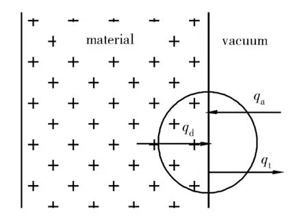
Fig. 1 Schematic diagram of desorption, adsorption and diffusion of a testing product
1.2 Outgassing models[4-5]
Generally, three outgassing models are well-known. First, Schram used the standard conductance method to measure the outgassing properties of typical nonmetal materials in room temperature. He obtained the outgassing law based on the adsorption theory and gave the formula for solid nonmetal material’s outgassing rate in certain condition, which is called the Schram adsorption model. Second is the diffusion model, which is suitable to explain the outgassing properties of glass and stainless steel (type of 1Cr18Ni9Ti). Third, Malev considered re-adsorption phenomena on a metal surface in outgassing. He did many experiments and proposed the adsorption-diffusion model.
2 Theoretical outgassing rate of typical testing products
Generally speaking, the outgassing rate of a material is a continuous function of time[6]. We can obtain the theoretical outgassing rate of typical testing products of different materials. Solid materials can dissolve a lot of gas. The higher the pressure of the gas is, the more gas will be dissolved. The gas concentration of materials should be as small as possible. When gas concentration is small enough, it can be described as[7]
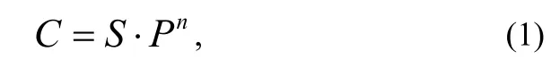
where: Cis the gas concentration in the testing product; Sis the solubility; P is the gas pressure outside of the solid; and n is an exponent.
Outgassing is mainly caused by diffusion. Inner gas of materials is concentrated in pockets, and the gas will diffuse inside the solid because of different gas concentrations. When these materials are put into a vacuum environment, the gases will escape from the materials.
The vacuum physics[8]provides two equations of outgassing rate for slabs. There is also an equation to determine which outgassing equation is to be used based on slab’s thickness. Outgassing rate of testing products, such as relay, conversion switch, driving framework may be analyzed by the diffusion of a cylinder.
The diffusion can be explained by Fick’s law, which includes Fick’s first law and Fick’s second law.
Fick’s first law is
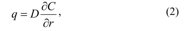
where: qis the specific outgassing rate; D is the diffusion coefficient.
Fick’s second law is
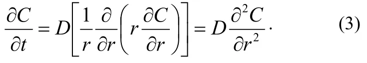
It is assumed that the radius of the cylinder is R. Initial and critical conditions are:
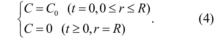
Assuming that C =uexp(- α2Dt), then equation (3) becomes
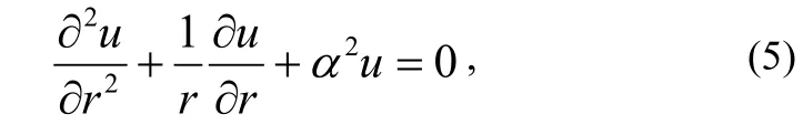
which is a Bessel equation. With equation (4), the gas concentration C is obtained as
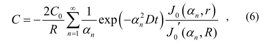
where: C0is the initial gas concentration in the testing product; J0is Bessel function of the first kind;is the first derivative of J0; α1,α2,…,αnare the roots of function J0.
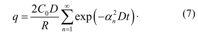
Using equation (6) and equation (2), the specific outgassing rate q is obtained as
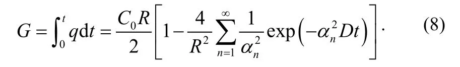
At time t, the amount of gas G is given by:
3 Measurement methods of outgassing rate
3.1 The constant volume method[9]
Outgassing rate of a testing product in an ultra-high vacuum chamber is proportional to the increase of pressure when the ultra-high vacuum valve is closed, and can be expressed as
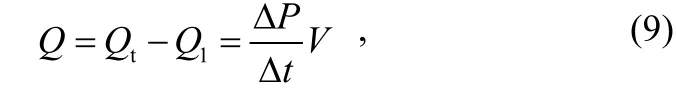
where: Q is the outgassing rate of the testing product; Qtis the total outgassing rate; Q1is the outgassing rate and leak rate in the ultra-high vacuum chamber;is the pressure changing rate of the chamber; V is the volume of the ultra-high vacuum chamber.
So the specific outgassing rate is

where S is the surface area of the testing product. A schematic diagram of the constant volume method is shown in Fig. 2.
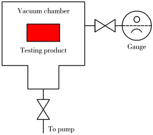
Fig. 2 Schematic diagram of the constant volume method
3.2 The orifice throughput method[9]
The orifice throughput method is widely used to measure the outgassing rates of testing products. Two vacuum gauges are used in a conventional measurement system of the orifice throughput method and the testing product is placed on the up-stream side. One gauge is on the up-stream side of an orifice and the other on the down-stream side.
The outgassing rate of the testing product Q is determined by
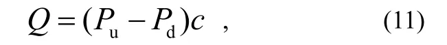
Where: Puand Pdare the pressures on the up-stream and down-stream sides, respectively, measured by those two gauges; cis the conductance of the orifice.
The specific outgassing rate of the testing product qis given by:
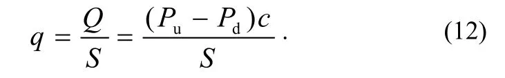
A schematic diagram of the orifice throughput method is shown in Fig. 3.
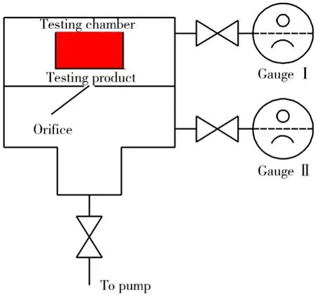
Fig. 3 Schematic diagram of the orifice throughput method
4 Problems of the orifice throughput method
Normally, the orifice throughput method is chosen for measuring the outgassing rate in ultra-high vacuum condition. But there are three problems related to this method[10].
Firstly, because the physical properties of the two gauges are not the same, we will have, for example, the iron effect of electron stimulated desorption (ESD), and X-ray limits, (Pu-Pd) in equation(11) might include some error when the pressures of the up-stream and down-stream sides are measured by two different gauges.
Secondly, the outgassed species can be readsorbed on the testing product and the testing chamber surfaces at the degassing process of the gauge head on the up-stream side.
Thirdly, the outgassing or pumping effect of the gauge head on the up-stream side can not be separated from the measured value Q.
5 Tackling the problems in the orifice throughput method
5.1 Description of the TGT method
Y. Yang, K. Saitoh and S. Tsukahara introduced and developed a modified orifice throughput method (TGT method) to measure the outgassing rate of a testing chamber[10], which will be used to measure the outgassing rate of a testing product. The schematic diagram of the TGT method is shown in Fig. 4.

Fig. 4 Schematic diagram of the TGT method
A cylindrical testing product is placed in the testing chamber, at the up-stream space, and the up- and down- stream sides of an orifice are connected by two bridges, each of which consists of one gauge head on a T-tube and two valves to terminate the tube. The combination of the gauge and the space to be measured is selected by the valve operation. In the arrangement there are two pressures to be measured, those of up-stream and down-stream space of the orifice, Puand Pd, respectively. And there are two gauges, namely GIand GII. Each bridge, gauge or valve is identified with the subscripts I and II for one and two, and “u” and “d” for the up- and down-stream sides, respectively.
5.2 Detailed approach
The measured value Q includes the contributions from the testing chamber, the gauge head and the testing product, i.e.
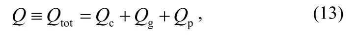
where Qtot, Qc,, Qgand Qprefer to the outgassing rate of the total, the testing chamber, the gauge head and the testing product, respectively.
If the outgassing rate of the testing product is much larger than that of the testing chamber, Qccan be neglected. So the outgassing rate and the specific outgassing rate of the testing product are given, respectively, by
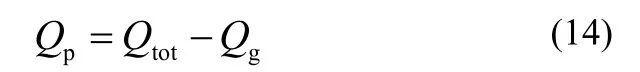
and

One valve of each bridge should be kept open for each gauge and then four combinations of valve states are possible as shown in Table 1, listed in the experimental order.
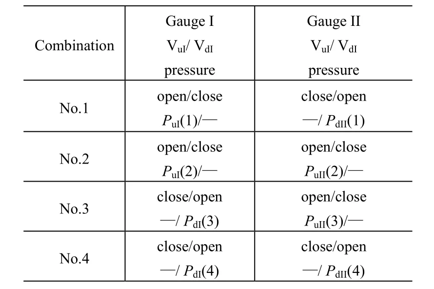
Table 1 Combination of valve states and the corresponding notation of the measured pressures by two gauges
According to equations(11) and(13), Qtotis expressed as
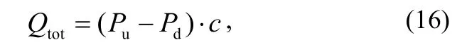
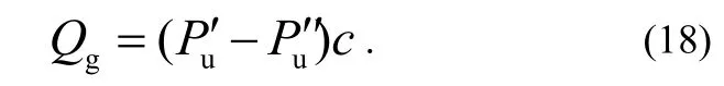
where both Puand Pdare measured by one and the same gauge that is defined as the main gauge. Then, the other gauge is used as the auxiliary one. The outgassing rate of the main gauge Qgin this configuration includes those of the connecting T-tube and the valves and is given as the derivative of Qtotwith and without the main gauge.

where the prime and the double prime refer to the gas pressures measured by the auxiliary gauge with and without the main gauge connected to the up-stream side, respectively. Since each combination from No.1 to No.4 can be selected by the valve operation without changing the pressure of down-stream side, i.e.Pd′ = Pd′ ′, then
It is possible to obtain Qpfrom the measured pressure values at the three combinations 1-3, as shown in Table 2. In case A or case B, we use GIor GIIas the main gauge, and GIIor GIas the auxiliary gauge to determine the outgassing rate of the main gauge QgIor QgII, respectively.
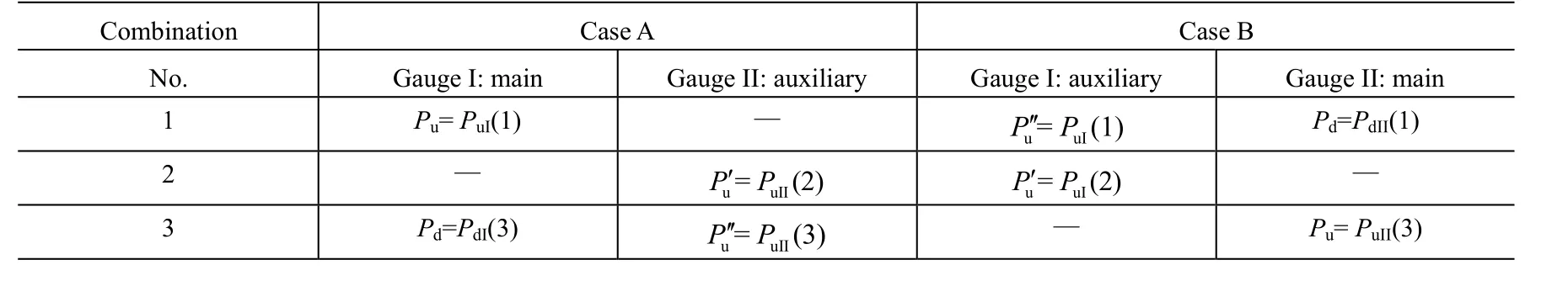
Table 2 Pressures used in the equations to calculate outgassing rates and the corresponding measured values in Table 1
In Case A or B, using the values of Table 1 in equation (14), (16) and (18), we can get the values of the Qtot, Qgand Qp, respectively.
5.3 Solution of the problems
Both of the pressure differences (Pu-Pd)and (Pu′ - Pu′′) in the calculation of Qtotand Qgare obtained by using the same gauge, GIand GII, respectively, then the errors due to the use of two gauges with different physical properties could be avoided and more accurate results can be obtained than those obtained by the orifice throughput method. Thus the first problem is solved.
The degassing of gauges is performed with VuIand VuIIclosed, and VdIand VdIIopen, then the testing product and the testing chamber surfaces are free from the contamination of involved gases with high sticking coefficient. Thus the second problem is solved, too.
By using the TGT method, the outgassing rate of gauge Qgis measured in situ and can be eliminated from the calculation of the outgassing rate of the testing product Qp, thus the third problem is solved.
6 Conclusion
By using Fick’s law, we can obtain the formula for calculating the theoretical outgassing rate of typical testing products. By using TGT method, we can measure accurately the outgassing rate of the testing products by eliminating the contribution from the vacuum and gauges used in the measurement. A better method should be found to eliminate the effect of outgassing from the testing chamber in future if the latter can not be ignored.
[1] 达道安. 真空设计手册[M]. 3版. 北京: 国防工业出版社, 2004: 1330-1331
[2] Wang Li, Yan Rongxin, Sun Lichen, et al. Outgassing analysis of ultra-high vacuum[J], 航天器环境工程, 2009, 26(2):158-161
[3] 孙立臣, 童靖宇, 汪力, 等. 环模设备研制用玻璃钢的放气性能研究[J]. 航天器环境工程, 2007, 24(2): 104-105
[4] 杨春光, 肖尤明, 陈楠, 等. 真空下非金属材料放气模型与研究综述[J]. 真空, 2006, 43(3): 48-50
[5] 陈丕瑾. 真空技术的科学基础[M]. 北京: 国防工业出版社, 1987: 315-356
[6] 龚建华. 真空物理[M]. 合肥工业大学真空教研室, 2002: 163-164
[7] 陈涛, 李玉忠, 许忠旭, 等. 真空热试验中材料放气的放气量及其导热问题[J]. 航天器环境工程, 2006, 23(2): 103-104
[8] 高本辉, 崔素言. 真空物理[M]. 北京: 科学出版社, 1983: 585-596
[9] 曾祥坡. 真空材料放气率测试方法研究[C]∥第十五届全国质谱分析与检漏会议, 2009: 134-136
[10] Yang Y, Saitoh K, Tsukahara S. An improved throughput method for the measurement of outgassing rates of materials[J]. Vacuum, 1995, 46: 1371-1376