Void Fraction Distributions in Cold-gassed and Hot-sparged Three Phase Stirred Tanks with Multi-impeller*
2009-05-15CHENLei陈雷BAOYuyun包雨云andGAOZhengming高正明
CHEN Lei (陈雷), BAO Yuyun (包雨云) and GAO Zhengming (高正明)
Void Fraction Distributions in Cold-gassed and Hot-sparged Three Phase Stirred Tanks with Multi-impeller*
CHEN Lei (陈雷), BAO Yuyun (包雨云) and GAO Zhengming (高正明)**
School of Chemical Engineering, Beijing University of Chemical Technology, Beijing 100029, China
Vertical distributions of void fraction in gas-liquid and gas-liquid-solid stirred tanks have been measured in a fully baffled dished base vessel of 0.48 m diameter, using a conductivity probe. The impeller configuration (a hollow half elliptical blade dispersing turbine below two up-pumping wide blade hydrofoils, identified as HEDT+2WHU) recommended in previous work has been used in this work. The operating temperatures were 24°C and 81°C, identified as cold and hot respectively. The effects of superficial gas velocity, agitator speed and the corresponding power input on the local void fraction in two-phase systems are investigated and discussed. Results show that the increasing of agitator speed or gas flow rate leads to an increase in local void fraction at the majority of measurement points in both cold and hot systems. However, the uniformity of gas dispersion does not always increase as the raising of agitator speed and power input. In either cold or hot sparged conditions, the two- and three-phase systems have similar vertical profiles for void fraction, with maxima in similar locations; however, the void fractions are significantly lower in hot sparging than with cold. In cold operation the presence of particles leads to a lower void fraction at most points, although the local void fractions increase a little with the addition of solid particles at high temperature, in good agreement with the global gas holdup results, and the possible reasons are discussed in this paper. This work can give a better understanding of the differences between cold-gassed and hot-sparged three phase stirred tanks.
void fraction, conductivity probe, hot sparged reactor, dispersed gas distribution, multi-impeller
1 INTRODUCTION
Gas-liquid-solid stirred reactors are widely used in the chemical, mineral, and biochemical industries and wastewater treatment. Gas dispersion is not uniform among different regions of a stirred tank, even when stirred by a multi-impeller agitator. Bubble coalescence and breakup rates are believed to be different in various regions of the tank, resulting in different bubble sizes and gas-liquid mass transfer coefficients. However, a relatively uniform distribution of gas is desirable in many stirred reactors—such as fermenters in which aerobic bacteria normally require a certain range of dissolved oxygen concentration which is in turn closely related to the local void fraction. Complete analysis and optimized design cannot be realized if based only on the global information on performance properties. The distributions of void fraction throughout the tank would help to understand these differences in gas dispersion and mass transfer. On the other hand, development in computer technique and computational fluid dynamics (CFD) software encourages more and more researchers to focus on numerical simulation of gas dispersion in stirred tanks [1-5]. The validation of CFD investigations requires detailed information, such as the distribution of voids and solid particles, together with bubble sizes, all of which demand more investigation than simply the measurement of global properties.
During the last several years there appear a few investigations of gas dispersion in industrial gas-liquid reactors [6-10]. The selection of measurement technique is an important part in these studies. The measurement techniques of local gas-phase characteristics in multi-phase systems can be classified as non-invasive and invasive techniques [11]. Among these techniques, the conductivity probe is a traditional and convenient one [8, 12]. Conductivity probes are invasive techniques, but they will not disturb the flow field seriously if the volume of the probe is kept small compared to the scale of the whole flow field. The conductivity probe is suitable for both opaque and dense dispersions, although the minimum detectable bubble size is limited by the size of the probe tip. Gao. [13] measured the vertical void fraction distribution in cold gassed, hot sparged and boiling gas-liquid systems with multiple impeller agitators, using the conductivity probe method. Two distinct peaks are observed in the void fraction profiles, and the local void fractions are always less in the hot sparged case than that in cold sparging. However, the effects of agitation speed and gas flow rate on void fraction distribution, which are of great importance in industrial design, are not included in their investigations.
Three-phase systems are used in many industrial processes, including hydrogenation, oxidation, fermentation, evaporative crystallization and froth flotation. Extensive studies [14-17] of three phase systems have been reported during the last 30 years. All these investigations were carried out in ambient (.. “cold”) conditions where the vapor pressure of the liquid phase can be assumed to have little effect on the process. For many exothermic (.. “hot”) processes,.. oxidation, hydrogenation and polymerization, the vapor pressure should be taken into account. In our previous work [18-20], radical differences were reported between cold-gassed and hot-sparged stirred tanks. The absolute value of sparged relative power demand is generally higher in hot conditions than that in cold operation. As solid concentration is increased, there is little change in the total gas holdup at higher temperature, whereas the total gas holdup at ambient temperature decreases significantly. At a given total gas flow rate and power input, the total gas holdup in a hot sparged system is lower than that in cold conditions, but the difference is reduced from 50% to about 25% with increasing solid concentration. However, only these global measurements are not sufficient. The distribution of local void fraction in a three phase stirred tank is still an open question for both cold and hot-sparged systems.
This paper reports the effects of agitation speed and gas flow rate on local void fractions in multi-impeller gas-liquid system at both low and high temperatures. The relationship between the uniformity of local void fraction and the operating parameters, including the agitation speed, gas rates and temperature, are also discussed on basis of the voidage distribution. The effects of solid particles on the distribution of local void fraction in both cold and hot systems are also investigated.
2 EXPERIMENTAL
2.1 Equipment


Figure 1 Schematic of the experimental setup
Figure 2 Impellers
Four cylindrical heaters (each rated at 3 kW on full power) were mounted vertically in the base of the tank and located midway between two baffles. The vapor generated in the vessel was condensed in the condenser and returned to the stirred tank, maintaining the liquid inventory in the tank.
Air and deionized water were used for all the experiments. In order to ensure sufficient conductivity in the deionized water, a little phosphoric acid was added. The solid particles were glass beads of 90 µm mean diameter and density 2500 kg·m-3at a volumetric concentration of 9%. Air was purified by passing through three-stage filters and then sparged into the tank. The total gas rates, including the vaporized water, ranged from 10 to 25 m3·h-1(with corresponding superficial velocities were 0.0156 to 0.039 m·s-1based on the tank cross section). Agitator speeds ranged from 4 to 8 s-1. The liquid bulk temperatures in cold and hot conditions were 24ºC and 81ºC respectively, maintained within ±0.2ºC by a thermal resistance thermostat.
2.2 Measurement technique
In this work, the local void fraction was measured by using a needle point conductivity probe technique co-developed with Institute of Process Engineering of the Chinese Academy of Sciences. The hard stainless steel needle of 0.2 mm diameter, coated with insulating varnish, was used to serve as the sensor probe, as shown in Fig. 3. The varnish is hydrophobic, giving the probe a very short response time. A very short length was left uncoated at each needle tip for exposure to the experimental fluids as an electrode of the probe. The probe was supported by a stainless steel tube which serves as another electrode. In order to prevent the probe becoming polarized, an AC voltage was used.
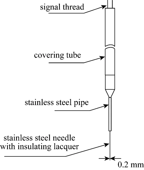
Figure 3 Construction of the electric conductivity probe
The principle of this technique is based on the difference in electrical conductivity between liquid and gas phases. During the measurement, the bubbles are pierced by the probe placed at a given position in gas-liquid flow. When the probe is in the gas phase, the measurement circuit is open, and a high voltage output signal is produced. When the probe is in the liquid phase, the measurement circuit is closed, giving a low voltage output. After amplifier, rectifier and smoothing circuits, square-wave signals are generated, as shown in Fig. 4.

Figure 4 Processed signals from the electric conductivity probe
The gas holdup is defined as the volume fraction of gas phase. If it is assumed that the local flow is homogeneous, the probe tip has an equal probability of piercing any point on the projected frontal area of an approaching bubble and the bubble-probe intercept varies from zero to the bubble diameter, the local void fraction corresponds to the probability that the probe tip is in the gas phase. The local void fraction was estimated using the time averaged quantity,, given by

wheregiis theth bubble passage time,bis the number of bubbles in the sample, andis the total sampling period.
In this work a sampling frequency of 10 kHz was used to collect the data from the sensor probe. In every group used in the measurement more than 500 bubbles were detected to obtain statistically representative data.
2.3 Saturation percentage of air in the hot sparged system
Throughout this paper the total volumetric gas flow rate in a hot-sparged system has been calculated by Eq. (3), which has been used and discussed in our previous papers [19, 20]:
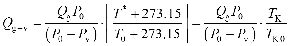
where*is the various hot sparged “equilibrium temperature” ranging in this paper from 24 to 81ºC,0is the temperature of the gas at inlet in centigrade,KandK0are “equilibrium temperatures” and inlet gas temperature in Kelvin, respectively.gis the inlet gas flow rate,0is the ambient pressure, andvis the saturated vapour pressure at*calculated by the Antoine equation. For the control temperatures of 24ºC and 81ºC in this work, the vapour pressure is 3 kPa and 50 kPa respectively.g+vis the total flow rate of the saturated gas.
3 RESULTS AND DISCUSSION
3.1 Effect of agitation speed on void fraction in cold and hot systems

Figure 5 Measurement points arrangement

/s-1: □ 4; ○ 5; △ 6; ▽ 7; ◇ 8
The comparison of data obtained in cold and hot systems at the same operating conditions [Fig. 6 (a). 6 (c) and Fig. 6 (b). 6 (d)] suggests that the gas void fraction at ambient temperature is generally higher than that at the same location but at higher temperature. This result is in good agreement with Gao. [13] who provided possible reasons to explain the difference of gas holdup between cold and hot systems. It should be noted that, as seen in Fig. 6, when the agitation speed is less than 5 s-1, the local gas void fraction near the bottom of the tank in a hot system is higher than that at ambient temperature.
This may be explained by a difference in the size of cavities behind the turbine blades in hot and cold systems. When a lot of gas is introduced into the tank with agitation at a relatively low power input, the cavities are larger in cold conditions than in hot liquid [20]. The pumping capacity of the impellers is therefore lower in cold system at low agitation speed, so less gas is circulated to the bottom of the tank. The large cavities in the cold system are gradually dispersed at higher agitator speeds. The pumping capacity of the impellers is then enhanced and the local gas holdup near the bottom increases.

/:■ 0.85;□ 0.7
The uniformity of gas dispersion in different regions of the stirred vessel cannot be evaluated from the overall gas holdup, though being of great importance in gas-liquid dispersion. In this work, the distributions of local void fraction in the bulk of the stirred tank were measured, providing the possibility of relating the uniformity of gas dispersion to different operating conditions. The dimensionless variation coefficient,, was used, as given in Eq. (4), to evaluate the uniformity of the gas dispersion.
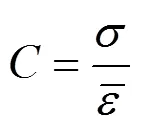

Figure 8 shows that given a constant superficial gas velocity, increasing the agitation speed at first leads to a rapid decrease in the variation coefficients of the void fraction distributions, but later the coefficients remain relatively constant and stable in both cold and hot systems. The higher value ofin a hot sparged system implies that the gas void fractions are less uniform than those in cold conditions at the same agitation speed or power input, as is seen in Fig. 8 (b). These stable variation coefficients mean that increasing the agitation speed or power input is not always helpful for the gas dispersion, especially with the gas superficial velocity of 0.031 m·s-1when the power input is already at a pretty high level such as 1.7 or 1.8 W·kg-1. Of course, this critical power input is closely related to the gas rate, and will decrease when less gas is introduced into the vessel: this will be discussed in the next section.
3.2 Effect of gas rate on void fraction in both cold and hot systems
Increasing the gas rate will increase the overall gas holdup. This is true of the local void fraction at most measurement points in the stirred tank as shown in Figs. 9 (a), 9 (b) and 9 (c), 9 (d) for both cold and hot conditions. However, the local void fraction near the bottom of the tank changes in a different way when gas rates are increased. It seems that the local void fraction there does not increase as much as in other regions of the tank, and even decreases a little in a cold system. On one hand, buoyancy will help bubbles to rise faster when more gas is introduced from the sparger, especially when the bottom impeller does not disperse the introduced gas well, which is exactly the case here.

■ cold systems;□ hot systems

s/m·s-1:□ 0.0156;○ 0.023;△ 0.031;▽ 0.039

■ cold systems;□ hot systems
Figure 10 also shows that the variation coefficientapproaches the stable value only at the lowest gas rate, which implies that this agitator speed (or power input) is not high enough to distribute higher gas rates. With a constant, relatively low, agitator speed, the cavities behind the turbine blades grow with an increased superficial gas velocity, weakening the pumping capacity of the impellers and also reducing the power input. When the superficial gas velocity is large enough, the gas dispersion gradually changes as the loaded impeller floods. In addition, gas distribution is even worse in a hot system than in cold, as reflected in the higher variation coefficientat similar gas rates.
Looking at Fig. 8 (a), it can be seen that with a superficial gas velocity of 0.031 m·s-1, when the agitation speed is increased from 6 to 7 s-1the variation coefficientdecreases from 0.347 to 0.288 very close to the constant value. This can be defined as the critical agitation speed with reference to reach a limiting value of. When the superficial velocity is increased to 0.039 m·s-1, the critical speed increases to 8 s-1where the variation coefficientis 0.290. The corresponding power inputs are also shown in parentheses in Fig. 10. When the superficial velocity is as low as 0.0156 m·s-1and the power input is 1.27 W·kg-1, the value ofis about 0.3. In order to reach a similar gas dispersion state at the superficial velocities of 0.031 and 0.039 m·s-1the power levels have to be increased to 1.75 and 2.53 W·kg-1, respectively. This information will be helpful in determining the power demand needed for industrial applications.
3.3 Effect of particles on local void fraction distribution in both cold and hot systems
Vertical distributions of void fraction in cold-gassed and hot-sparged two phase systems are shown in Fig. 11. As mentioned before the profiles are very similar, with two distinct peaks evident above the top and bottom impeller planes. Given the same total gas flow rates the local void fractions are always less in the hot-sparged system than those in cold conditions. This is in good agreement with the results of Gao. [13] who included some discussion about the difference between hot and cold systems, though that paper did not consider the effect of solids.
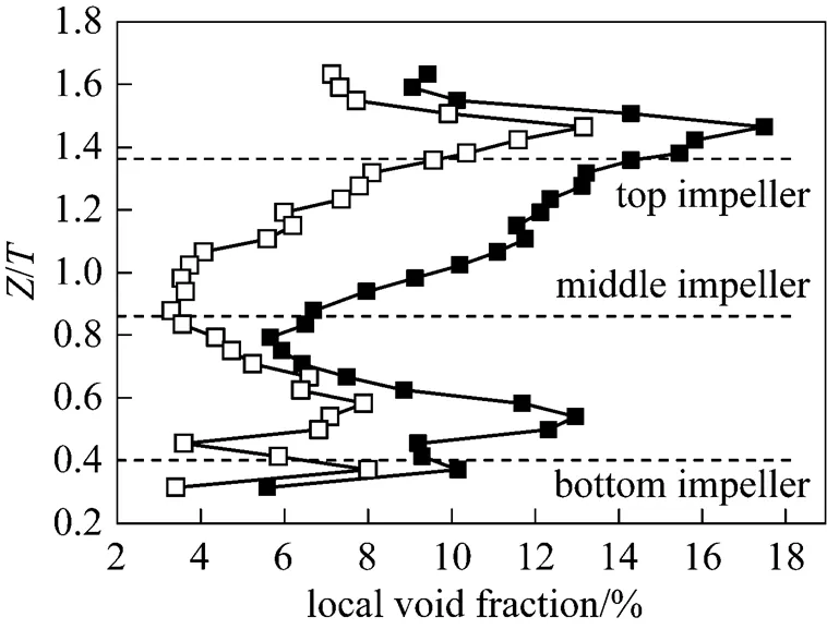
■ cold systems;□ hot systems
v: ■ 9%;□ 0%
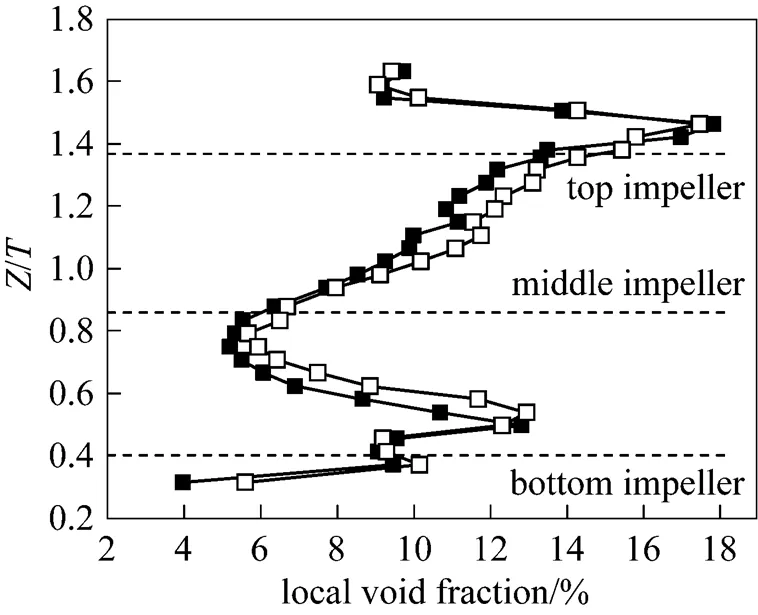
Our previous works [19, 20] have reported that the effects of solids on the overall gas holdup are quite different in cold and hot systems. The results showed that in a cold system the averaged gas holdup decreased significantly with an increase in solid concentration, but, in hot conditions, it was almost independent of the solid concentration, or even increased a little. Figs. 12 and 13 show the effect of solids on vertical void fraction distributions in cold and hot systems. It can be seen that particles at a volumetric concentration of 9% have little effect on the vertical void fraction distribution. Both two- and three-phase systems have similar void fraction profiles, with maxima at similar locations. Fig. 12 demonstrates that the presence of particles leads to a tendency of void fractions to be reduced at most measurement points in the cold system, which is similar to the results of our previous paper on overall gas holdup [19]. The probable reason for this was attributed to a change in bubble size between two and three phase conditions, a point which needs further study through the direct measurement of bubble size. The quantitative comparison for both local and overall gas hold-ups will be discussed later.

v: ■ 9%;□ 0%

Table 1 Comparison between overall gas holdup andvertical line average gas holdup
The local void fractions are always less in hot conditions than when cold, as is the rule in two phase systems. However, the temperature effect on void fractions in three phase systems is less than that in two phase ones, which can be seen by comparing the data in Table 1. When the temperature is increased from 24 to 81°C, the mean void fraction in a three phase system decreases from 9.7% to 7.1%, about 36%, but it changes by more than 60%, from 10.6% to 6.6% in the absence of solids.
4 CONCLUSIONS
The effects of agitation speed, superficial gas velocity and particles on the local void fraction in cold- gassed (24ºC) and hot-sparged (81ºC) gas-liquid dispersion system have been investigated in an agitated vessel of 0.48 m diameter agitated by a multi-impeller combination. A point conductivity probe was used for all measurements.
(1) With an increase in agitation speed or power input, the void fraction increases at most points in both cold and hot systems. With a fixed superficial gas velocity, an increased agitator speed leads to at first a more uniform gas void fraction distribution in the vessel, followed by a relatively stable level at relatively high power input levels when an increase in agitation speed or power input does not always help in distributing the gas. The gas void fractions in hot-sparged systems are less uniform than those in cold-gassed systems at similar agitation speeds or power input.
(2) An increase in gas rate increases the local void fraction at most measurement points in both cold and hot systems. However, at a constant agitation speed, a higher sparge rate leads to a less uniform distribution and a greater power input is needed to distribute the gas more uniformly.
(3) The presence of solid particles at a volumetric concentration of 9% has little effect on the vertical void fraction distributions. Both two- and three-phase systems have similar void fraction profiles, with maxima at similar locations. However, the presence of particles leads to tendency to decrease the void fraction at most locations in the cold system, against a trend of increase in hot conditions. The temperature effect on the void fractions in three-phase systems is not as great as that in two-phase ones.
ACKNOWLEDGEMENTS
The authors sincerely acknowledge the helpfuldiscussion with Prof. John M. Smith [Fluids and SystemsResearch Centre, School of Engineering (J2), Universityof Surrey, Guildford, GU2 7XH, UK].
NOMENCLATURE
variation coefficient
diameter of impeller, m
height of liquid in tank (general), m
agitation speed, s-1
bnumber of bubbles in the sample
ginlet gas flow rate, m3·s-1
g+vtotal gas flow rate including both air and vapour, m3·s-1
radius of the tank, m
distance between the measurement point and the center of the tank, m
diameter of the tank, m
0ambient temperature of the air,°C
*equilibrium temperature in hot sparged system,°C
total sampling period, s
githeth bubble passage time, s
ssuperficial gas velocity, m·s-1
axial height of measurement points, m
local void fraction
standard deviation
1 Wang, W.J., Mao, Z.S., “Numerical simulation of gas-liquid flow in a stirred tank with a Rushton impeller”,...., 10, 385-395 (2002).
2 Lane, G.L., Schwarz, M.P., Evans, G.M., “Numerical modeling of gas-liquid flow in stirred tanks”,..., 60, 2203-2214 (2005).
3 Khopkar, A.R., Kasat, G.R., Pandit, A.B., Ranade, V.V., “CFD simulation of mixing in tall gas-liquid stirred vessel: Role of local flow patterns”,..., 61, 2921-2929 (2006).
4 Min, J., Bao, Y., Chen, L., Gao, Z., Smith, J.M., “Numerical simulation of gas dispersion in an aerated stirred reactor with multiple impellers”,...., 47, 7112-7117 (2008).
5 Murthy, B.N., Kasundra, R.B., Joshi, J.B., “Hollow self-inducing impellers for gas-liquid-solid dispersion: Experimental and computational study”,..., 141, 332-345 (2008).
6 Lu, W., Ju, S., “Local gas holdup, mean liquid velocity and turbulence in an aerated stirred tank using hot-film anemometry”,..., 35, 9-17 (1987).
7 Gao, Z., Wang, Y., Shi, L., Fu, J., “Theoretical and experimental studies on bubble diameter and gas holdup in aerated stirred tanks”,...., 4 (4), 283-289 (1996).
8 Barigou, M., Greaves, M., “Gas holdup and interfacial area distributions in a mechanically agitated gas-liquid contactor”,., 74 (A), 397-405 (1996).
9 Laakkonen, M., Honkanen, M., Saarenrinne, P., Aittamaa, J., “Local bubble size distributions, gas-liquid interfacial areas and gas holdups in a stirred vessel with particle image velocimetry”,..., 109, 37-47 (2005).
10 Gao, Z., Smith, J.M., Müller-Steinhagen, H., “Gas dispersion in sparged and boiling reactors”,...., 79, 973-978 (2001).
11 Boyer, C., Duquenne, A.M., Wild, G., “Measuring techniques in gas-liquid and gas-liquid-solid reactors”,..., 57, 3185-3215 (2002).
12 Sun, K., Zhang, M., Chen, X., “Local measurement of gas-liquid bubbly flow with a double-sensor probe”,...., 8 (1), 33-40 (2000).
13 Gao, Z., Smith, J.M., Muller-Steinhagen, H., “Void fraction distribution in sparged and boiling reactors with modern impeller configuration”,..., 40, 489-497 (2001).
14 Nienow, A.W., Bujalski, W., “Recent studies on agitated three-phase (gas-solid-liquid) systems in the turbulent regime”,., 80 (A), 832-838 (2002).
15 Wen, J., Zhou, H., Chen, Y., “Local gas phase flow characteristics of a gas-liquid-solid three-phase reversed flow jet loop reactor”,...., 10 (1), 119-122 (2002).
16 Bao, Y., Hao, Z., Gao, Z., Shi, L., Smith, J.M., “Suspension of buoyant particles in a three phase stirred tank”,..., 60, 2283-2292 (2005).
17 Bao, Y., Hao, Z., Gao, Z., Shi, L., Smith, J.M., Thorpe, R.B., “Gas dispersion and solid suspension in a three-phase stirred tank with multiple impellers”,..., 193, 801-825 (2006).
18 Gao, Z., Shi, L., “Effect of temperature on gas hold-up in aerated stirred tanks”,...., 11 (2), 204-207 (2003).
19 Bao, Y.Y., Chen, L., Gao, Z.M., Zhang, X., Smith, J.M., Kirkby, N.F., “Temperature effects on gas dispersion and solid suspension in a three-phase stirred reactor”,...., 47, 4270-4277 (2008).
20 Bao, Y.Y., Zhang, X., Gao, Z.M., Chen, L., Smith, J.M., Kirkby, N.F., “Gas dispersion and solid suspension in a hot sparged multi-impeller stirred tank”,...., 47, 2049-2055 (2008).
2009-06-19,
2009-10-16.
the National Natural Science Foundation of China (20576009, 20821004) and the National Basic Research Program of China (2007CB714300).
** To whom correspondence should be addressed. E-mail: gaozm@mail.buct.edu.cn
猜你喜欢
杂志排行

Chinese Journal of Chemical Engineering的其它文章
- Study on the Flow Field around Two Parallel Moving Bubbles andInteraction Between Bubbles Rising in CMC Solutions by PIV*
- Kinetic Rate Constant of Liquid Drainage from Colloidal Gas Aphrons*
- β-Diketones at Water/Supercritical CO2 Interface: A MolecularDynamics Simulation*
- Analysis of Sucrose Esters with Long Acyl Chain by Coupling ofHPLC-ELSD with ESI-MS System*
- Adsorptive Removal of Copper Ions from Aqueous Solution UsingCross-linked Magnetic Chitosan Beads
- Gas Flow in Unilateral Opening Pulse Tubes Based on Real Gas Equation of State