Design and Performance Analysis of Micro Proton Exchange Membrane Fuel Cells*
2009-05-12ZHONGZhenzhong钟振忠CHENJunxun陈俊勋andPENGRonggui彭荣贵
ZHONG Zhenzhong (钟振忠), CHEN Junxun (陈俊勋) and PENG Ronggui (彭荣贵)
Design and Performance Analysis of Micro Proton Exchange Membrane Fuel Cells*
ZHONG Zhenzhong (钟振忠)**, CHEN Junxun (陈俊勋) and PENG Ronggui (彭荣贵)
Department of Mechanical Engineering, National Chiao Tung University, Hsinchu 300, China
This study describes a novel micro proton exchange membrane fuel cell (PEMFC) (active area, 2.5 cm2). The flow field plate is manufactured by applying micro-electromechanical systems (MEMS) technology to silicon substrates to etch flow channels without a gold-coating. Therefore, this investigation used MEMS technology for fabrication of a flow field plate and presents a novel fabrication procedure. Various operating parameters, such as fuel temperature and fuel stoichiometric flow rate, are tested to optimize micro PEMFC performance. A single micro PEMFC using MEMS technology reveals the ideal performance of the proposed fuel cell. The optimal power density approaches 232.75 mW·cm-1when the fuel cell is operated at ambient condition with humidified, heated fuel.
micro proton exchange membrane fuel cell, flow field plate, micro-electromechanical systems technology, silicon
1 INTRODUCTION
A proton exchange membrane fuel cell (PEMFC) with hydrogen as the anode fuel has immense promise as a future power system because of its high efficiency and low level of pollution generated. Research into and development of PEMFCs have garnered considerable attention. Hu. [1] developed a numerical model for a PEMFC and simulated basic transport phenomena as gas-liquid two-phase flows in a working fuel cell. Shao. [2] generated a dynamic thermal- transfer model of a PEMFC stack, which was based on energy conservation to improve the temperature control of the PEMFC stack. Zhang. [3] studied the degradation mechanism of key components of in a PEMFC membrane electrode assembly (MEA) and identified feasible measures to avoid degradation. Moreover, the novel MEA is particularly suitable for portable electronic power applications. Notably, PEMFCs have characteristics suited to consumer electronic devices. Consequently, the increased demand for a portable and efficient electrical power supply led to the development of micro fuel cell technology. Conventional fuel cells are manufactured using traditional Computer Numeric Control (CNC) technology; however, micro fuel cells are fabricated using Micro-electromechanical Systems (MEMS) technology. The potential applications of micro fuel cells have increased significantly since 2000, driven by a well-defined need of the consumer electronics industry for micro PEMFCs that outperform secondary lithium batteries [4].
Early in 2000, Lee. [5] applied microfabrication techniques, such as deep silicon etching, photomasked electroplating, physical vapor deposition, anodic bonding, and spin coating, to silicon wafers to create flow channels. They produced milliwatt fuel cells using novel techniques and materials. Their micro fuel cells have an efficiency of 150 mA·cm-2. Hahn. [6] developed a planar PEMFC with a cross sectional area between 1 mm2and 1 cm2at the silicon wafer level. They analyzed various patterning technologies to fabricate micro flow fields, and achieved a power density of 80 mW·cm-2during long-term operation. Yohtaro [7] applied micro fabrication technology to preparation processes for micro fuel cells. Yohtaro showed that micro PEMFCs had higher output power than micro direct methanol fuel cells (DMFCs). Hsieh. [8] developed a novel design and fabrication process for a micro fuel-cell flow-field plate with a cross sectional area of 5 cm2and thickness of 800 μm. Their novel design had a power density of 25 mW·cm-2at 0.65 V, and a reliable and stable output power at ambient temperatures. In another study, Hsieh. [9] used the SU-8 photoresist microfabrication process to fabricate micro PEMFC flow structures. The I-V curve of performance shows a modest voltage drop over a very small range of current. Their work contributed to the low-cost mass-production of small flat single fuel cells with a power density of 30 mW·cm-2at 0.35 V. Chan. [10] developed a micro fuel cell using polymeric micromachining. The membrane electrode assembly was embedded in a gold-coated polymethyl methacrylate substrate. The operating conditions included dead-ending of hydrogen in the anode. Chan. showed that the power output by the 3 cm2fuel cell was 0.947 W when pure hydrogen was fed to the anode and pure oxygen was supplied to the cathode at room temperature. When air was utilized on the cathode side, power output reached 0.246 W. The design of the base substrate and electrodes performed well. Hydrogen was set to be dead-ended; thus, the utilization of hydrogen was nearly 100%.
In 2006, Cha. [11] studied transport phenomena in micro fuel-cell flow channels. The channels were 500 μm, 100 μm and 20 μm wide and constructed using a structural photopolymer. The effects of channel size and the gas diffusion layer (GDL) thickness on performance were examined. A large pressure drop in very small channels improved the convection of air into the GDL and improved fuel cell performance at low current densities. Cha. indicated that using a thin GDL improved micro fuel cell performance. Kim. [12] investigated the fabrication process and electrochemical characterization of a miniaturized PEMFC with silicon separators. The micro channels on the silicon separator were created by a photolithographic process. The micro channels were 400 μm wide and 230 μm deep. The single cell with these silicon separators had a power density of 203 mW·cm-2at 0.6 V, which is similar to that of a conventional non-silicon fuel cell. Kim. indicated that a silicon separator can be applied successfully as an alternative to conventional bipolar plates for a micro PEMFC. Hsieh. [13] investigated the operational parameters of a H2/air micro PEMFC with different flow configurations by impedance spectroscopy. Their study considered a range of operating parameters, such as backpressure and cell temperature, to determine how flow configuration affected micro fuel cell performance. Optimal operating conditions were utilized to test the micro PEMFC stack [14]. Hsieh. demonstrated that the effects of operational parameters, including magnitude, on stack performance are similar to those on a single cell. Xiao. [15], who developed a silicon-based PEMFC power system, indicated that the catalyst with a high active surface area was monolithically integrated with the major fuel cell components using the sputtering method. Lee and Chuang [16] employed porous silicon as a gas diffusion layer in a micro fuel cell. The platinum (Pt) catalyst was deposited on the surface of, and inside, the porous silicon by physical vapor deposition, to improve porous silicon conductivity. Porous silicon with Pt catalyst replaced the conventional GDL, and the Pt metal remaining on the rib was used to form a micro-thermal sensor in a single lithographic process. Lee. demonstrated that temperature was almost linearly related to resistance. Feng. [17] developed a novel method of producing silicon-based microfabricated electrodes with high electrochemical active surface area (EASA) and high catalyst utilization. Feng. showed that the Si-based membrane electrode assembly (MEA) system exhibited a power density of 23.4 mW·cm-2. Seyfang. [18] developed a novel, simplified concept for polymer electrolyte micro-fuel cells. For different flow fields, a maximum power density was ~415 mW·cm-2at a cell voltage of 425 mV. Zhang. [19] developed a novel porous gas diffusion medium with improved thermal and electrical conductivities and controllable porosity fabricated from a metal foil using micro/nano technology in a PEMFC. The performance of the novel GDL was enhanced by applying a microporous layer (MPL) to the GDL, and by enhancing in-plane transport. Renaud. [20] studied the hydrodynamic flow characteristics in microfluidic devices. The 2D model combined with Navier-Stokes equations and the no-slip condition were sufficient to describe and calculate flows in 20 μm deep microchannels etched in silicon; the derived flows were in good agreement with measured flows.
A micro PEMFC is defined as one that generates <5 W of electricity. The preferred substrate material in a flow field plate is silicon because of its suitability to MEMS technology. In this study, MEMS technology is employed to a silicon wafer to embed flow channels in a micro fuel cell.
This study focuses applies MEMS technology to a silicon wafer to manufacture flow channels and tests micro fuel cell performance under different ambient conditions. Various operational conditions are experimentally utilized to optimize cell performance. This work develops a novel and simple method for manufacturing efficient micro PEMFCs.
2 DESIGN AND FABRICATION OF MICRO PEMFC
A typical micro PEMFC has an end plate, gasket, GDL, MEA, flow field plate and current collector. Fig. 1 (a) presents a schematic diagram of a micro PEMFC. Fig. 1 (b) displays the fabricated single micro PEMFC with all components.

Figure 1 Micro PEMFC
The end plate, made of acrylic resin, is 45 mm× 45 mm×13 mm. The gasket, made of silica gel, is 1 mm thick. This gasket isolates and prevents gas leakage. The 0.4-mm-thick GDL is made of standard carbon paper (CARBEL CL GDL). The MEA, which is 0.035 mm thick, catalyst loading of the anode and cathode is 0.5 (mg Pt)·cm-2, is a commercial product. The micro PEMFC reaction area is 2.5 cm2.
A single micro PEMFC is assembled using two flow field plates. Silicon is used for the substrate in the anode and cathode flow field plates. The micro PEMFC is manufactured using MEMS technology. The objective of the silicon wafer etching process is to create micro PEMFC channels. Photolithography is used to transfer flow channel geometric shapes on a mask onto the surface of a silicon wafer. The steps in the photolithography process are wafer cleaning, deposit silicon nitride, spin coating the resist, soft baking, mask alignment and exposure, development, and hard baking. Fig. 2 shows the fabrication procedure for the silicon wafer. A silicon wafer 1.016 m in diameter is employed as the substrate in this investigation.
Contaminants on the surface of silicon wafers at the start of the MEMS technology process or accumulated during processing must be removed during processing to obtain high-performance and highly reliable semiconductor devices, and prevent equipment contamination, especially under high-temperature oxidation, diffusion and deposition tubes. In this study, RCA (Radio Corporation of America) cleaning is a four-step process for removing organic contaminants, the oxide layer, ions, and heavy metal contaminants from the wafer surface over a 1.016 m, (100)-oriented 750-μm-thick silicon wafer.
A spinner is used to dry the wafer after RCA cleaning. A 200-nm silicon nitride layer is deposited by low-pressure chemical vapor deposition (LPCVD). One side of the silicon wafer is polished, and the silicon substrate is then spin-coated with a resistive layer 7 μm thick at various rotating speeds.

Figure 2 Silicon wafer etching process
The silicon substrate is then soft baked. Soft baking removes most solvents from the photoresist coating. A positive photoresist is then employed. The photoresist is exposed to ultraviolet (UV) light wherever the underlying material must be removed. The g-line is used during the exposure process in this study. After exposure, heat is applied for approximately 2-3 min for post-exposure baking. Development is done in the vitrics to form micro flow channels.
The photoresist is then hard-baked for about 1 min. After development, the silicon substrate is examined. The flow structure cavities are patterned by wet etching. Reactive ion etching (RIE) is applied to etch a silicon nitride layer 300 μm wide. Notably, RIE, an etching technology used during microfabrication, uses chemically reactive plasma to remove materials deposited on wafers. Plasma is generated under low pressure in an electromagnetic field. However, the silicon nitride layer is too thin for the fuel to flow from the inlet to the outlet. Hence, the exposed silicon wafer is etched to pattern micro PEMFC channels in an aqueous solution of 45% KOH at 80°C. Etched channel depth is 500 μm. This depth promotes gas uniformity, water management and reduced flow resistance. Next, the photoresist is removed from the silicon substrate. The final step employs phosphoric acid to remove the remaining silicon nitride at 180°C.
Figure 3 Silicon substrates after etching process
Three serpentine channels, each 300 μm wide and 500 μm deep, are etched into the sides of the anode and cathode. The fuel holes are drilled into the rear of silicon wafer. The oversize flow field plates are 25 mm×25 mm. A silicon wafer 1.016 m in diameter is used to make four flow field plates. Fig. 3 shows the silicon substrate after etching.
Current collectors provide an electrical pad for transmission of electricity to the external load. Unlike metal, silicon is not considered an ideal current collector due to its high electrical resistance. In this investigation, the silicon wafer is only used as a fuel carrier. Therefore, an alternative design in this study uses an MEA and GDL sandwiched between current collectors made of brass foil; this design replaces conventional bipolar plates. Consequently, silicon substrates are rarely used for flow field plates as electrons do not pass through silicon substrates. The advantage of this novel design is that no Au electroplate is required on the top of the silicon wafer. The only requirement is that current collectors be hollowed out to enable fuel to diffuse to the MEA.
In this study of the micro PEMFC fabrication procedure, the MEA is sandwiched between two GDLs, two current collectors, two flow field plates, two gaskets and two end plates. The assembled structures are clamped together with four screws.
3 EXPERIMENTAL
To obtain a micro PEMFC polarization curve, the micro PEMFC test has a gas supply unit, electrical load, power supply, computer, fuel humidifier, fuel temperature controller and mass flow controller. Fig. 4 shows the experimental setup. The gas supply unit provides fuel and the oxidant to the micro fuel cell. The electrical load is a device that simulates loading on an electrical circuit. Counter to the current source, the electrical load is a current sink. The load current is regulated electronically. The range of measured currents is 0-15 A and maximum power output is 75 W. The power supply supplies electricity to each component in this experimental test. A computer regulates all installations orders and evaluates experimental results. The micro PEMFC structure cannot be heated because the end plate is made of acrylic resin. Therefore, a humidifier and temperature controller are used to humidify and heat the fuel to improve micro PEMFC performance. The flow rates of hydrogen, oxygen and air are regulated by mass flow controllers. Notably, the flow rate through this mass flow controller cannot be <10 cm3·min-1in the anode and 20 cm3·min-1in the cathode. The micro PEMFC is connected to the electrical load. Polarization curves are plotted after the micro PEMFC reaches a steady state. Various fuel temperatures and fuel flow rates are tested. The fuel flow rates that generate a current of 1 A are calculated based on the theoretical volume. The flow rates of hydrogen and oxygen are 7.6 and 3.8 cm3·min-1·A-1, respectively. Therefore, the flow rates are multiplied by the stoichiometric value of 1.37 to obtain a value of 10.4 cm3·min-1·A-1for the anode, and 1.84 to yield 7.0 cm3·min-1·A-1for the cathode.

Figure 4 Schematic diagram of the experimental setup
4 RESULTS AND DISCUSSION
The objective of this study is to develop a process for fabricating a micro PEMFC with a simple structure using MEMS technology applied to a silicon substrate. A single micro PEMFC is assembled and used in the polarization curve experiment. Optimal operating conditions are identified.
Figure 5 plots the micro PEMFC polarization curves obtained at fuel temperatures of 30, 40, 50, 60, 70 and 80°C. The experiment is performed at ambient pressure and temperature; pure humidified hydrogen and oxygen are fed into the micro PEMFC. The stoichiometric flow rate is fixed at 3 (H2is 31.2 cm3·min-1and O2is 21.0 cm3·min-1). The current densities are 436.77, 421.82, 402.00, 469.58, 488.27 and 490.83 mA·cm-2, respectively, at 0.46 V. The performance at a fuel temperature of 70°C is similar to that at 80°C. The average power densities are 222.16 and 223.32 mW·cm-2, indicating that the best fuel temperatures for the micro PEMFC are 70 and 80°C in this experiment. Experimental results show that a high fuel temperature increases gas diffusivity and membrane conductivity. Therefore, a high fuel temperature induces electrochemical reactions. This experimental result indicates that cell performance is increases as fuel temperature increases. Restated, micro PEMFC performance depends on fuel temperature.
Figure 5 I-V curves at different fuel temperatures ● 30°C;▲ 40°C;■ 50°C;★ 60°C; × 70°C;◆ 80°C
Figure 6 Comparison of polarization curves at four operating fuel stoichiometric flow rates at 70°C● 70°C stoich 3;▲ 70°C stoich 4;■ 70°C stoich 5;★ 70°C stoich 6
Four operating fuel stoichiometric flow rates are employed to study their effects on micro PEMFC performance. The fuel stoichiometric flow rates are 3, 4, 5 and 6 (H2, 31.2, 41.6, 52.0, 62.4 cm3·min-1; O2, 21.0, 28.0, 35.0, 42.0 cm3·min-1). The experiment is performed at ambient pressure and temperature. Pure humidified hydrogen and oxygen are fed into the micro PEMFC while fuel temperature is maintained at 70°C. Fig. 6 plots experimental results obtained with the four fuel stoichiometric flow rates. When the initial fuel stoichiometric flow rate is 6, cell performance is poorest; that is, current density at 0.46 V is 453.27 mA·cm-2. For fuel stoichiometric flow rates of 3, 4 and 5, the current densities at 0.46 V are 468.00, 505.98 and 504.60 mA·cm-2, respectively. Therefore, internal flooding is not obvious. However, a fuel stoichiometric flow rate of 4 yields a performance slightly better than that obtained with other stoichiometric flow rates. Maximum power output with a fuel stoichiometric flow rate of 4 is 232.75 mW·cm-2. This experimental result indicates that the fuel stoichiometric flow rate markedly affects cell performance,.., micro fuel cell performance improves gradually as the fuel stoichiometric flow rates increase. Increasing gas velocity improves the removal of water produced by the cathode. However, the fuel stoichiometric flow rate of 6 dries out the membrane, which increases electrical resistance. Therefore, the fuel stoichiometric flow rate of 6 generates the worst performance.
Figure 7 presents the micro PEMFC polarization behavior when the fuel stoichiometric flow rates are changed from H2/O2to 3, 4 and 5. The experiment is performed at ambient pressure and temperature. Pure humidified hydrogen and oxygen are fed into the micro PEMFC. Fuel temperature is controlled at 80°C. As the stoichiometric flow rate increases, cell performance worsens. As mentioned, increasing fuel temperature accelerates reactions, and increases the amount of liquid water produced, which adversely affects cell performance. Humidified H2and O2are fed into the micro fuel cell. Accordingly, the amount of liquid water is generated increases when the high current density. Notably, high humidification can cause excessive water accumulation that can flood the channels. Therefore, when the fuel temperature is 80°C and fuel flow rates are high, cell performance is worse than that when fuel temperature is 70°C. However, when the stoichiometric flow rate of fuel is 4, the reaction is optimal at a fuel temperature of 70°C.
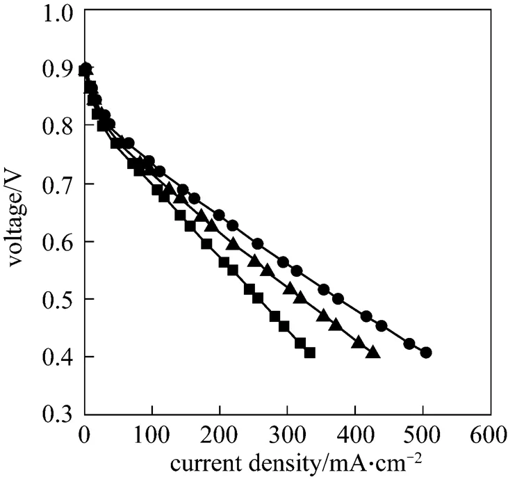
Figure 7 Comparison of polarization curves at three operating fuel stoichiometric flow rates at 80°C ● 80°C stoich 3;▲ 80°C stoich 4;■ 80°C stoich 5
Figure 8 plots polarization curves of pure humidified hydrogen and air (70°C), which are used as reactant gases under ambient conditions. The flow of H2/air are controlled with stoichiometric flow rates of 1, 2 and 3 (H2is 10.4, 20.8, 31.2 cm3·min-1and air is 35.0, 70.0, 105.0 cm3·min-1). The performance is poorer than when pure oxygen is used in the cathode; experimental results demonstrate that current densities are 139.03, 149.90 and 166.65 mA·cm-2, respectively, at 0.46 V. This experiment indicates that a fixed stoichiometric flow rate of 5 optimizes performance of micro PEMFC when the cathode fuel is air.
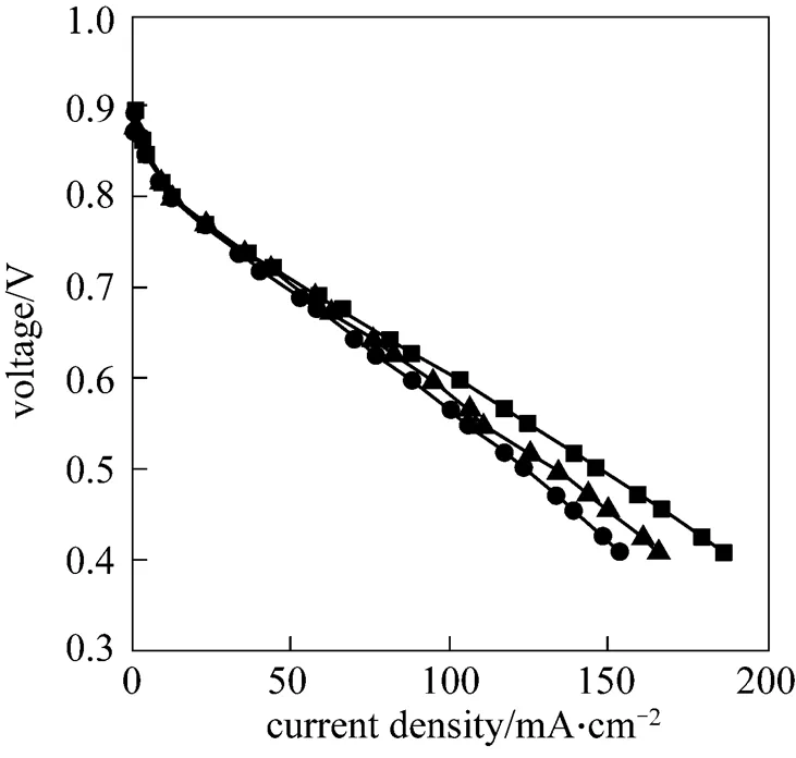
Figure 8 Comparison of polarization curves at three operating fuel (H2/air) stoichiometric flow rates at 70°C ● 70°C H2/air stoich 1;▲ 70°C H2/air stoich 2; ■ 70°C H2/air stoich 3
Additionally, experimental results demonstrate that the performance of micro PEMFC exceeds expectations.The optimal current density is 505.98 mA·cm-2at 0.46 V for a pure hydrogen and pure oxygen stoichiometric flow rate of 4 at a fuel temperature of 70°C.
5 CONCLUSIONS
Portable consumer electronic devices require small, lightweight power supplies with high electricity capacity. Micro PEMFCs meet this requirement. The study employs MEMS technology to etch flow field channels into a silicon substrate. The reaction area of this single micro PEMFC is 2.5 cm2. A single micro PEMFC is successfully fabricated and favorable performance achieved. The optimal power density approaches 232.75 mW·cm-2at 0.46 V when the cell is operated at ambient conditions with humidified and heated fuel. The objective of future work is to assemble serial interconnected single micro PEMFCs in a micro PEMFC stack.
ACKNOWLEDGEMENTS
.
1 Hu, M.R., Zhu, X.J., Gu, A.Z., “Simulation of the internal transport phenomena for PEM fuel cells with different modes of flow”,...., 12, 14-26 (2004).
2 Shao, Q.L., Wei, D., Gao, G.Y., Zhu, X.J., “Dynamic thermal model and temperature control of proton exchange membrane fuel cell stack”,...., 13, 218-224 (2005).
3 Zhang, S.S., Yu, H.M., Zhu, H., Hou, J.B., Yi, B.L., Ming, P.W., “Effects of freeze/thaw cycles and gas purging method on polymer electrolyte membrane fuel cells”,...., 14, 802-805 (2006).
4 Vielstich, W., Lamm, A., Gasteiger, H. A., Handbook of Fuel Cells, West Sussex, England (2003).
5 Lee, S.J., Cha, S.W., Liu, Y., O’Hayre, R., Prinz, F.B., “High power-density polymer-electrolyte fuel cells by microfabrication”, Electrochemical Society Proceedings (2000).
6 Hahn, R., Wagner, S., Schmitz, A., Reichl, H., “Development of a planar micro fuel cell with thin film and micro patterning technologies”,, 131, 73-78 (2004).
7 Yohtaro, Y., “Application of MEMS technology to micro fuel cells”,, 50, 663-666 (2004).
8 Hsieh, S.S., Kuo, J.K., Hwang, C.F., Tsai, H.H., “A novel design and microfabrication for a micro PEMFC”,, 10, 121-126 (2004).
9 Hsieh, S.S., Hwang, C.F., Kuo, J.K., Tsai, H.H., Yang, S.H., “SU-8 flow field plates for a micro PEMFC”,, 9, 121-131 (2005).
10 Chan, S.H., Nguyen, N.T., Xia, Z., Wu, Z., “Development of a polymeric micro fuel cell containing laser-micromachined flow channels”,, 15, 231-236 (2005).
11 Cha, S.W., O’Hayre, R., Park, Y.I., Prinz, F.B., “Electrochemical impedance investigation of flooding in micro-flow channels for proton exchange membrane fuel cells”,, 161, 138-142 (2006).
12 Kim, J.Y., Kwon, O.J., Hwang, S.M., Kang, M.S., Kim, J.J., “Development of a miniaturized polymer electrolyte membrane fuel cell with silicon separators”,, 161, 432-436 (2006).
13 Hsieh, S.S., Yang, S.H., Feng, C.L., “Characterization of the operational parameters of a H2/air micro PEMFC with different flow fields by impedance spectroscopy”,, 162, 262-270 (2006).
14 Hsieh, S.S., Feng, C.L., Huang, C.F., “Development and performance analysis of a H2/air micro PEM fuel cell stack”,, 163, 440-449 (2006).
15 Xiao, Z., Yan, G., Feng, C., Chan, P.C.H., Hsing, I.M., “A silicon-based fuel cell micro power system using a microfabrication technique”,, 16, 2014-2020 (2006).
16 Lee, C.Y., Chuang, C.W., “A novel integration approach for combining the components to minimize a micro-fuel cell”,, 172, 115-120 (2007).
17 Feng, C., Chan, P.C.H., Hsing, I.M., “Catalyzed microelectrode mediated by polypyrrole/nafion composite film for microfabricated fuel cell applications”,, 9, 89-93 (2007).
18 Seyfang, B.C., Kuhnke, M., Lippert, T., Scherer, G.G., Wokaum, A., “A novel, simplified micro-PEFC concept employing glassy carbon micro-structures”,, 9, 1958-1962 (2007).
19 Zhang, F.Y., Advani, S.G., Prasad, A.K., “Performance of a metallic gas diffusion layer for PEM fuel cells”,, 176, 293-298 (2008).
20 Renaud, L., Malhaire, C., Kleimann, P., Barbier, D., Morin, P., “Theoretical and experimental studies of microflows in silicon microchannels”,, 28, 910-917 (2008).
2008-09-29,
2008-11-27.
the National Science Council (NSC 97-2221-E-009-067).
** To whom correspondence should be addressed. E-mail: chenchung.me93g@nctu.edu.tw
杂志排行

Chinese Journal of Chemical Engineering的其它文章
- Isolation of Cordyceps ophioglossoides L2 from Fruit Body and Optimization of Fermentation Conditions for Its Mycelial Growth*
- Efficient and Comprehensive Utilization of Hemicellulose in the Corn Stover*
- Simulating Surface Aeration Systems at Different Scale of Mixing Time*
- Kinetics of Reaction-Crystallization of Struvite in the Continuous Draft Tube Magma Type Crystallizers—Influence of Different Internal Hydrodynamics
- Preparation and Characterization of Tungsten-substituted Molybdophosphoric Acids and Catalytic Cyclodehydration of 1,4-Butanediol to Tetrahydrofuran*
- Facile Preparation of Danazol Nanoparticles by High-Gravity Anti-solvent Precipitation (HGAP) Method*